 | –≠–ª–µ–∫—Ç—Ä–æ–Ω–Ω—ã–π –∫–æ–º–ø–æ–Ω–µ–Ω—Ç: SD700C40L | –°–∫–∞—á–∞—Ç—å:  PDF PDF  ZIP ZIP |

SD700C..L SERIES
STANDARD RECOVERY DIODES
Hockey Puk Version
700A
Bulletin I2096 rev. B 04/00
1
www.irf.com
Features
Wide current range
High voltage ratings up to 4500V
High surge current capabilities
Diffused junction
Hockey Puk version
Case style DO-200AB (B-PUK)
Typical Applications
Converters
Power supplies
High power drives
Auxiliary system supplies for traction applications
Major Ratings and Characteristics
I
F(AV)
700
A
@ T
hs
55
∞C
I
F(RMS)
1310
A
@ T
hs
25
∞C
I
FSM
@
50Hz
7500
A
@ 60Hz
7850
A
I
2
t
@
50Hz
281
KA
2
s
@ 60Hz
257
KA
2
s
V
RRM
range
3000 to 4500
V
T
J
- 40 to 150
∞C
Parameters
SD700C..L
Units
case style DO-200AB (B-PUK)

SD700C..L Series
2
Bulletin I2096 rev. B 04/00
www.irf.com
Voltage
V
RRM
, maximum repetitive
V
RSM
, maximum non-
I
RRM
max.
Type number
Code
peak reverse voltage
repetitive peak rev. voltage
@ T
J
= T
J
max.
V
V
mA
30
3000
3100
36
3600
3700
40
4000
4100
45
4500
4600
ELECTRICAL SPECIFICATIONS
Voltage Ratings
SD700C..L
50
I
F(AV)
Max. average forward current
700 (345)
A
180∞ conduction, half sine wave
@ Heatsink temperature
55 (85)
∞C
Double side (single side) cooled
I
F(RMS)
Max. RMS forward current
1310
A
@ 25∞C heatsink temperature double side cooled
I
FSM
Max. peak, one-cycle forward,
7500
t = 10ms
No voltage
non-repetitive surge current
7850
t = 8.3ms
reapplied
6310
t = 10ms
50% V
RRM
6600
t = 8.3ms
reapplied
Sinusoidal halfwave,
I
2
t
Maximum I
2
t for fusing
281
t = 10ms
No voltage
Initial T
J
= T
J
max.
257
t = 8.3ms
reapplied
199
t = 10ms
50% V
RRM
182
t = 8.3ms
reapplied
I
2
t
Maximum I
2
t for fusing
2810
KA
2
s
t = 0.1 to 10ms, no voltage reapplied
V
F(TO)1
Low level value of threshold
voltage
V
F(TO)2
High level value of threshold
voltage
r
f
1
Low level value of forward
slope resistance
r
f
2
High level value of forward
slope resistance
V
FM
Max. forward voltage drop
1.66
V
I
pk
= 1000A, T
J
= T
J
max, t
p
= 10ms sinusoidal wave
A
KA
2
s
0.88
(16.7% x
x I
F(AV)
< I <
x I
F(AV)
), T
J
= T
J
max.
Parameter
SD700C..L
Units
Conditions
Forward Conduction
V
m
0.78
(16.7% x
x I
F(AV)
< I <
x I
F(AV)
), T
J
= T
J
max.
0.99
(I >
x I
F(AV)
),T
J
= T
J
max.
0.73
(I >
x I
F(AV)
),T
J
= T
J
max.

SD700C..L Series
3
Bulletin I2096 rev. B 04/00
www.irf.com
R
thJ-hs
Conduction
(The following table shows the increment of thermal resistence R
thJ-hs
when devices operate at different conduction angles than DC)
Ordering Information Table
1
-
Diode
2
-
Essential part number
3
-
0 = Standard recovery
4
-
C = Ceramic Puk
5
-
Voltage code: code x 100 = V
RRM
(see Voltage Ratings Table)
6
-
L = Puk Case DO-200AB (B-PUK)
1
2
3
4
5
6
Device Code
SD
70
0
C
45
L
Sinusoidal conduction
Rectangular conduction
Conduction angle
Units
Conditions
Single Side Double Side
Single Side Double Side
180∞
0.011
0.011
0.008
0.008
120∞
0.014
0.015
0.014
0.014
90∞
0.018
0.018
0.019
0.019
K/W
T
J
= T
J
max.
60∞
0.026
0.026
0.027
0.028
30∞
0.045
0.046
0.046
0.046
T
J
Max. junction operating temperature range
-40 to 150
T
stg
Max. storage temperature range
-55 to 200
R
thJ-hs
Max. thermal resistance, junction
0.11
DC operation single side cooled
to heatsink
0.05
DC operation double side cooled
F
Mounting force, ± 10%
9800
N
(1000)
(Kg)
wt
Approximate weight
250
g
Case style
DO-200AB(B-PUK)
See Outline Table
Parameter
SD700C..L
Units
Conditions
Thermal and Mechanical Specifications
∞C
K/W
SD700C..L Series
4
Bulletin I2096 rev. B 04/00
www.irf.com
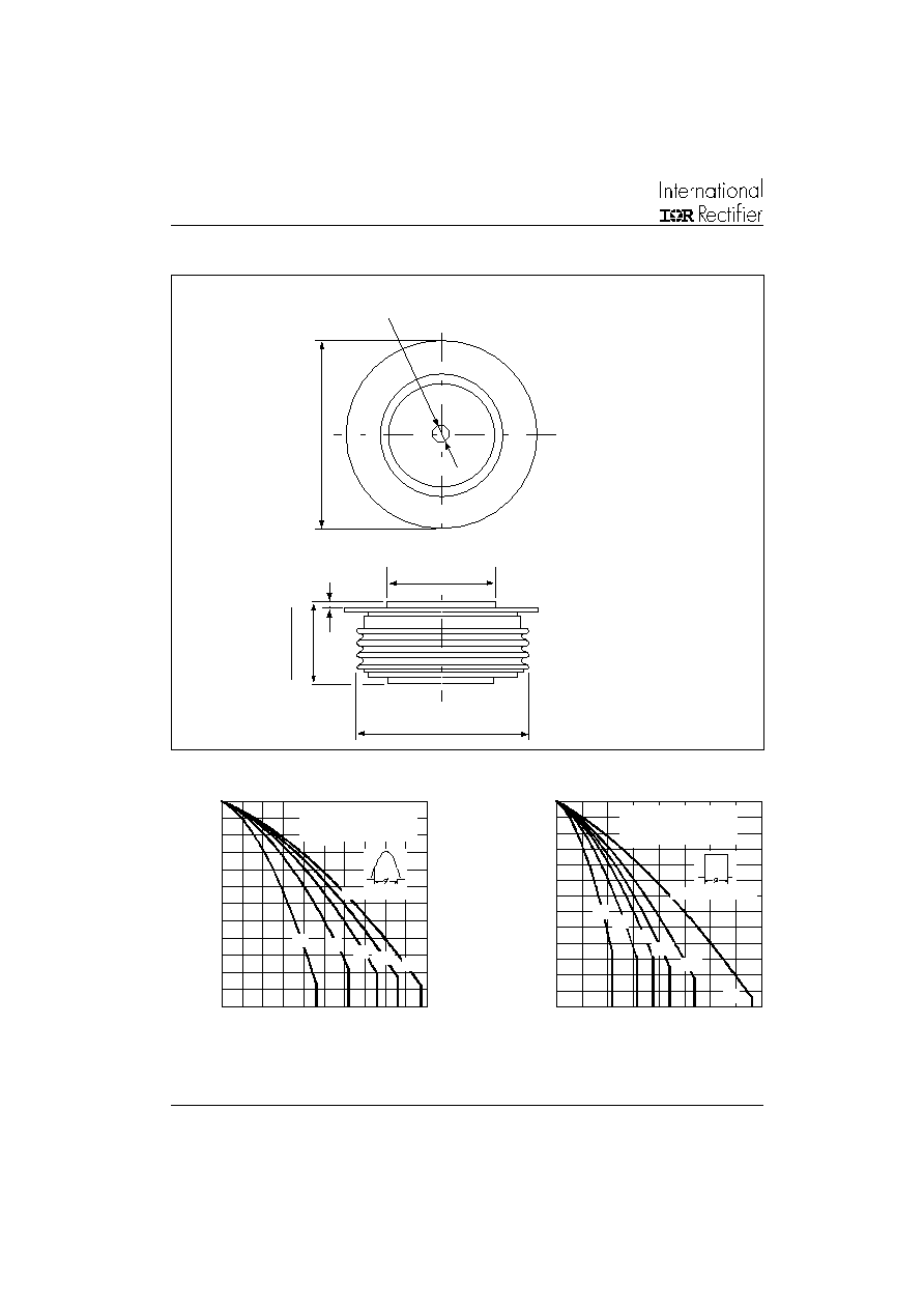
Outline Table
Fig. 1 - Current Ratings Characteristics
Fig. 2 - Current Ratings Characteristics
3 0
4 0
5 0
6 0
7 0
8 0
9 0
10 0
11 0
12 0
13 0
14 0
15 0
0
10 0
2 0 0
3 00
40 0
5 0 0
3 0∞
60 ∞
90∞
12 0∞
18 0∞
Average Forward Cur ren t (A)
M
a
x
i
m
u
m A
l
l
o
w
a
bl
e
He
at
s
i
n
k
T
e
m
p
e
r
at
u
r
e
(
∞
C
)
SD70 0C..L Series
( Single Side Cooled)
R (DC) = 0.11 K/W
th J -hs
C o nd u ct io n A ng le
2 0
3 0
4 0
5 0
6 0
7 0
8 0
9 0
10 0
11 0
12 0
13 0
14 0
15 0
0
2 0 0
4 00
60 0
80 0
30∞
6 0∞
90∞
180∞
DC
1 20∞
Average For ward Current (A)
M
a
x
i
mu
m
A
l
l
o
w
a
b
l
e
H
e
a
t
s
i
n
k
T
e
mp
e
r
a
t
u
r
e
(
∞
C)
SD70 0C..L Series
( Single Side Cooled)
R (D C) = 0.11 K/W
th J -hs
C o nd u ctio n Pe rio d
BOTH ENDS
0.8 (0.03)
TWO PLACES
3.5(0.14) DIA. NOM. x
1.8(0.07) DEEP MIN.
34 (1.34) DIA. MAX.
5
8
.5
(
2
.
3
0
)
D
I
A
.
M
A
X
.
26
.
9
(
1
.
06)
25.
4
(
1
)
BOTH ENDS
53 (2.09) DIA. MAX.
Case Style DO-200AB (B-PUK)
All dimensions in millimeters (inches)
Quote between upper and lower
pole pieces has to be considered
after application of Mounting Force
(see Thermal and Mechanical
Specification)

SD700C..L Series
5
Bulletin I2096 rev. B 04/00
www.irf.com
Fig. 4 - Current Ratings Characteristics
Fig. 6 - Forward Power Loss Characteristics
2 0
3 0
4 0
5 0
6 0
7 0
8 0
9 0
10 0
11 0
12 0
13 0
14 0
15 0
0
20 0
4 0 0
6 0 0
80 0 10 0 0 1 20 0 1 40 0
3 0∞
60∞
9 0∞
180∞
D C
12 0∞
Average For ward Current (A)
M
a
x
i
mu
m
A
l
l
o
w
a
bl
e
He
at
s
i
n
k
T
e
m
p
e
r
at
u
r
e
(
∞
C)
SD700C..L Series
(Double Side Cooled)
R (DC) = 0.05 K/W
thJ - hs
Co n d uc tio n Pe rio d
1 0
2 0
3 0
4 0
5 0
6 0
7 0
8 0
9 0
10 0
11 0
12 0
13 0
14 0
15 0
0
2 0 0
4 0 0
60 0
8 00
1 00 0
30∞
6 0∞
90∞
120 ∞
1 80∞
Average Forward Current (A)
M
a
x
i
mu
m
A
l
l
o
w
a
bl
e
He
at
s
i
n
k
T
e
m
p
e
r
at
u
r
e
(
∞
C)
SD700 C..L Series
(Double Side Cooled)
R (DC) = 0.05 K/W
th J -hs
C o nd uctio n A ng le
0
50 0
1 0 00
1 5 00
2 0 00
2 5 00
0
2 00
40 0
6 0 0
8 00 1 0 00 1 2 00 1 40 0
DC
18 0∞
12 0∞
9 0∞
6 0∞
3 0∞
Aver age Forward Current (A)
RM S Lim it
M
a
x
i
m
u
m
A
v
e
r
ag
e
F
o
r
w
ar
d P
o
w
e
r
L
o
s
s
(
W
)
SD 700 C..L Ser ies
T = 15 0∞C
J
C o nd uctio n P erio d
0
50 0
1 00 0
1 50 0
2 00 0
2 50 0
0
20 0
4 0 0
6 0 0
8 00
10 0 0
180 ∞
120 ∞
90 ∞
60 ∞
30 ∞
Average For ward Curr ent (A)
M
a
x
i
mu
m A
v
e
r
a
g
e
F
o
r
w
a
r
d
P
o
w
e
r
L
o
s
s
(
W
)
RM S Lim it
SD70 0C..L Series
T = 150∞C
J
Co n d uc tio n An g le
Fig. 7 - Maximum Non-Repetitive Surge Current
Single and Double Side Cooled
Fig. 8 - Maximum Non-Repetitive Surge Current
Single and Double Side Cooled
20 0 0
30 0 0
40 0 0
50 0 0
60 0 0
70 0 0
1
10
1 0 0
N um b e r O f Eq ua l A m p lit ud e H a lf C y cle C urre nt P uls e s (N )
P
e
a
k
H
a
l
f
S
i
ne
W
a
v
e
F
o
r
w
a
r
d
C
u
r
r
e
n
t
(
A
)
SD700 C..L Series
In itial T = 15 0 ∞C
@ 60 Hz 0.0 083 s
@ 50 Hz 0.0 100 s
J
At Any Rated Load Con dition And W ith
50 % Rated V Applied Followin g Surge
RR M
1 0 0 0
2 0 0 0
3 0 0 0
4 0 0 0
5 0 0 0
6 0 0 0
7 0 0 0
8 0 0 0
9 0 0 0
0 .0 1
0 .1
1
Pulse Train Duration (s)
P
e
ak
Hal
f
S
i
n
e
W
a
v
e
F
o
r
w
ar
d C
u
r
r
e
n
t
(
A
)
Maxim um Non Repetitive Surge Curr en t
SD7 00C..L Series
5 0% Rated V Reapplied
No Voltage Reapplied
In itial T = 15 0 ∞C
RR M
J
V ersus Pulse Train Duration.
Fig. 3 - Current Ratings Characteristics
Fig. 5 - Forward Power Loss Characteristics

SD700C..L Series
6
Bulletin I2096 rev. B 04/00
www.irf.com
Fig. 10 - Thermal Impedance Z
thJ-hs
Characteristics
Fig. 9 - Forward Voltage Drop Characteristics
1 0 0
10 0 0
1 00 0 0
0 .5
1
1. 5
2
2 .5
3
3 .5
4
T = 2 5∞C
J
Ins tan tan eous Forward Voltage (V)
I
n
st
a
n
t
a
n
e
o
u
s
F
o
rw
a
r
d
C
u
rre
n
t
(
A
)
SD 700C..L Series
T = 150∞C
J
0 . 0 0 1
0 . 0 1
0 . 1
1
0 . 0 0 1
0 . 0 1
0 . 1
1
1 0
S qu a re W a v e P ulse D u r at io n ( s)
S D 7 0 0 C .. L S e rie s
th
J
-
h
s
T
r
a
n
s
i
en
t
T
h
er
m
a
l
I
m
p
e
d
a
n
c
e Z
(
K
/
W
)
S t e a d y S t a te V alue
R = 0 . 1 1 K /W
( S in g le Sid e C o o le d )
R = 0 . 0 5 K /W
( D o ub le Sid e C o o le d )
( D C O pe ra tio n )
thJ -hs
thJ -hs