Äîêóìåíòàöèÿ è îïèñàíèÿ www.docs.chipfind.ru

DISCRETE POWER DIODES and THYRISTORS
DATA BOOK
Next Data Sheet
Index
Previous Datasheet
To Order

620A
INVERTER GRADE THYRISTORS
Puk Version
ST303C..C SERIES
Bulletin I25172/A
case style TO-200AB (E-PUK)
Features
Metal case with ceramic insulator
International standard case TO-200AB (E-PUK)
All diffused design
Center amplifying gate
Guaranteed high dV/dt
Guaranteed high dI/dt
High surge current capability
Low thermal impedance
High speed performance
Typical Applications
Inverters
Choppers
Induction heating
All types of force-commutated converters
Major Ratings and Characteristics
(*) t
q
= 10 to 20µs for 400 to 800V devices
t
q
= 15 to 30µs for 1000 to 1200V devices
I
T(AV)
620
A
@ T
hs
55
°C
I
T(RMS)
1180
A
@ T
hs
25
°C
I
TSM
@
50Hz
7950
A
@ 60Hz
8320
A
I
2
t
@
50Hz
316
KA
2
s
@ 60Hz
289
KA
2
s
V
DRM
/V
RRM
400 to 1200
V
t
q
range (*)
10 to 30
µs
T
J
- 40 to 125
°
C
Parameters
ST303C..C
Units
Next Data Sheet
Index
Previous Datasheet
To Order
ST303C..C Series
Voltage
V
DRM
/V
RRM
, maximum
V
RSM
, maximum
I
DRM
/I
RRM
max.
Type number
Code
repetitive peak voltage
non-repetitive peak voltage
@ T
J
= T
J
max.
V
V
mA
04
400
500
08
800
900
10
1000
1100
12
1200
1300
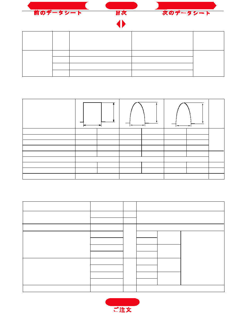
ELECTRICAL SPECIFICATIONS
Voltage Ratings
Frequency
Units
50Hz
1314
1130
2070
1940
6930
6270
400Hz
1260
1040
2190
1880
3440
2960
1000Hz
900
700
1900
1590
1850
1540
A
2500Hz
340
230
910
710
740
560
Recovery voltage Vr
50
50
50
50
50
50
Voltage before turn-on Vd
V
DRM
V
DRM
V
DRM
Rise of on-state current di/dt
50
50
-
-
-
-
A/
µ
s
Heatsink temperature
40
55
40
55
40
55
°C
Equivalent values for RC circuit
10
/ 0.47µF
10
/ 0.47µF
10
/ 0.47µF
I
TM
180
o
el
180
o
el
100
µ
s
I
TM
I
TM
Current Carrying Capability
V
ST303C..C
50
I
T(AV)
Max. average on-state current
620 (230)
A
180° conduction, half sine wave
@ Heatsink temperature
55 (85)
°C
double side (single side) cooled
I
T(RMS)
Max. RMS on-state current
1180
DC @ 25°C heatsink temperature double side cooled
I
TSM
Max. peak, one half cycle,
7950
t = 10ms
No voltage
non-repetitive surge current
8320
A
t = 8.3ms
reapplied
6690
t = 10ms
100% V
RRM
7000
t = 8.3ms
reapplied
Sinusoidal half wave,
I
2
t
Maximum I
2
t for fusing
316
t = 10ms
No voltage
Initial T
J
= T
J
max
289
t = 8.3ms
reapplied
224
t = 10ms
100% V
RRM
204
t = 8.3ms
reapplied
I
2
t
Maximum I
2
t for fusing
3160
KA
2
s
t = 0.1 to 10ms, no voltage reapplied
Parameter
ST303C..C
Units
Conditions
On-state Conduction
KA
2
s
To Order
Next Data Sheet
Index
Previous Datasheet
ST303C..C Series
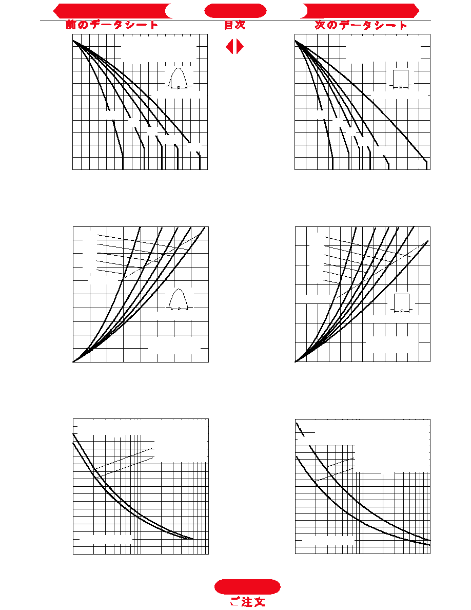
Fig. 3 - Current Ratings Characteristics
Fig. 4 - Current Ratings Characteristics
Fig. 5 - On-state Power Loss Characteristics
Fig. 6 - On-state Power Loss Characteristics
Fig. 8 - Maximum Non-repetitive Surge Current
Fig. 7 - Maximum Non-repetitive Surge Current
To Order
Next Data Sheet
Index
Previous Datasheet
ST303C..C Series
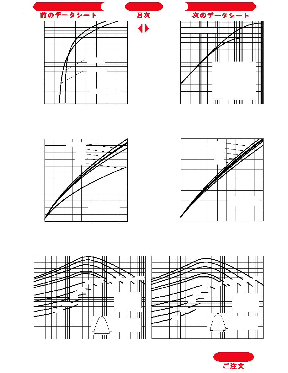
Fig. 9 - On-state Voltage Drop Characteristics
Fig. 10 - Thermal Impedance Z
thJ-hs
Characteristics
Fig. 11 - Reverse Recovered Charge Characteristics
Fig. 12 - Reverse Recovery Current Characteristics
Fig. 13 - Frequency Characteristics
To Order
Next Data Sheet
Index
Previous Datasheet