Features
Electrically isolated base plate
Types up to 1200 V
RRM
3500 V
RMS
isolating voltage
Simplified mechanical designs,
rapid assembly
High surge capability
Large creepage distances
UL E78996 approved
I
F(AV)
40
70
85
110
A
I
F(RMS)
63
110
134
173
o
C
I
FSM
50Hz
570
1200
1700
2000
A
60Hz
600
1250
1800
2100
A
I
2
t
50Hz
1630
7100
14500
20500
A
2
s
60Hz
1500
6450
13500
18600
A
2
s
I
2
t
16300
70700 148700 204300 A
2
s
V
RRM
range
100 to 1200
V
T
J
-40 to 150
o
C
These series of T-modules use standard recovery
power rectifier diodes. The semiconductors are
electrically isolated from the metal base, allowing
common heatsink and compact assembly to be built.
Applications include power supplies, battery charges,
welders, motor controls and general industrial current
rectification.
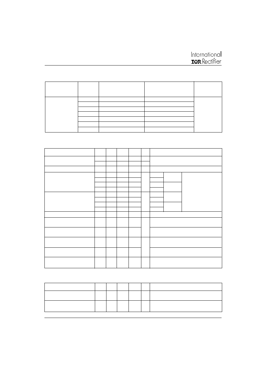
Description
Parameters
T40HF T70HF T85HF T110HF Units
Major Ratings and Characteristics
1
POWER RECTIFIER DIODES
T-Modules
40 A
70 A
85 A
110 A
T..HF SERIES
Bulletin I27106 rev. B 02/02
www.irf.com
T..HF Series
2
Bulletin I27106 rev. B 02/02
www.irf.com
I
F(AV)
Max. average fwd current
40
70
85
110
A
180
o
conduction, half sine wave
@ Case temperature
85
85
85
85
o
C
I
F(RMS)
Max. RMS forward current
63
110
134
173
A
I
FSM
Max. peak, one-cycle
570
1200
1700
2000
A
t = 10ms No voltage
forward,non-repetitive
600
1250
1800
2100
t = 8.3ms reapplied
surge current
480
1000
1450
1700
t = 10ms 100% V
RRM
500
1050
1500
1780
t = 8.3ms reapplied
Sinusoidal half wave,
I
2
t
Maximum I
2
t for fusing
1630
7100
14500
20500
A
2
s t = 10ms No voltage
Initial T
J
= T
J
max.
1500
6450
13500
18600
t = 8.3ms reapplied
1150
5000
10500
14500
t = 10ms 100% V
RRM
1050
4570
9600
13200
t = 8.3ms reapplied
I
2
t
Maximum I
2
t for fusing
16300 70700 148700 204300 A
2
s t = 0.1 to 10ms, no voltage reapplied
V
F(TO)1
Low level value of threshold
0.66
0.76
0.68
0.68
V
(16.7% x
x I
F(AV)
< I <
x I
F(AV)
), @ T
J
max.
voltage
V
F(TO)2
High level value of threshold
0.84
0.95
0.90
0.86
(I >
x I
F(AV)
), @ T
J
max.
voltage
r
f1
Low level value of forward
4.3
2.4
1.76
1.56
m
(16.7% x
x I
F(AV)
< I <
x I
F(AV)
), @ T
J
max.
slope resistance
r
f2
High level value of forward
3.1
1.7
1.08
1.12
(I >
x I
F(AV)
), @ T
J
max.
slope resistance
V
FM
Max. forward voltage drop
1.30
1.35
1.27
1.35
V
I
FM
=
x I
F(AV)
, T
J
= 25
o
C, tp = 400
�
s square pulse
Av. power = V
F(TO)
x I
F(AV)
+ r
f
x (I
F(RMS)
)
2
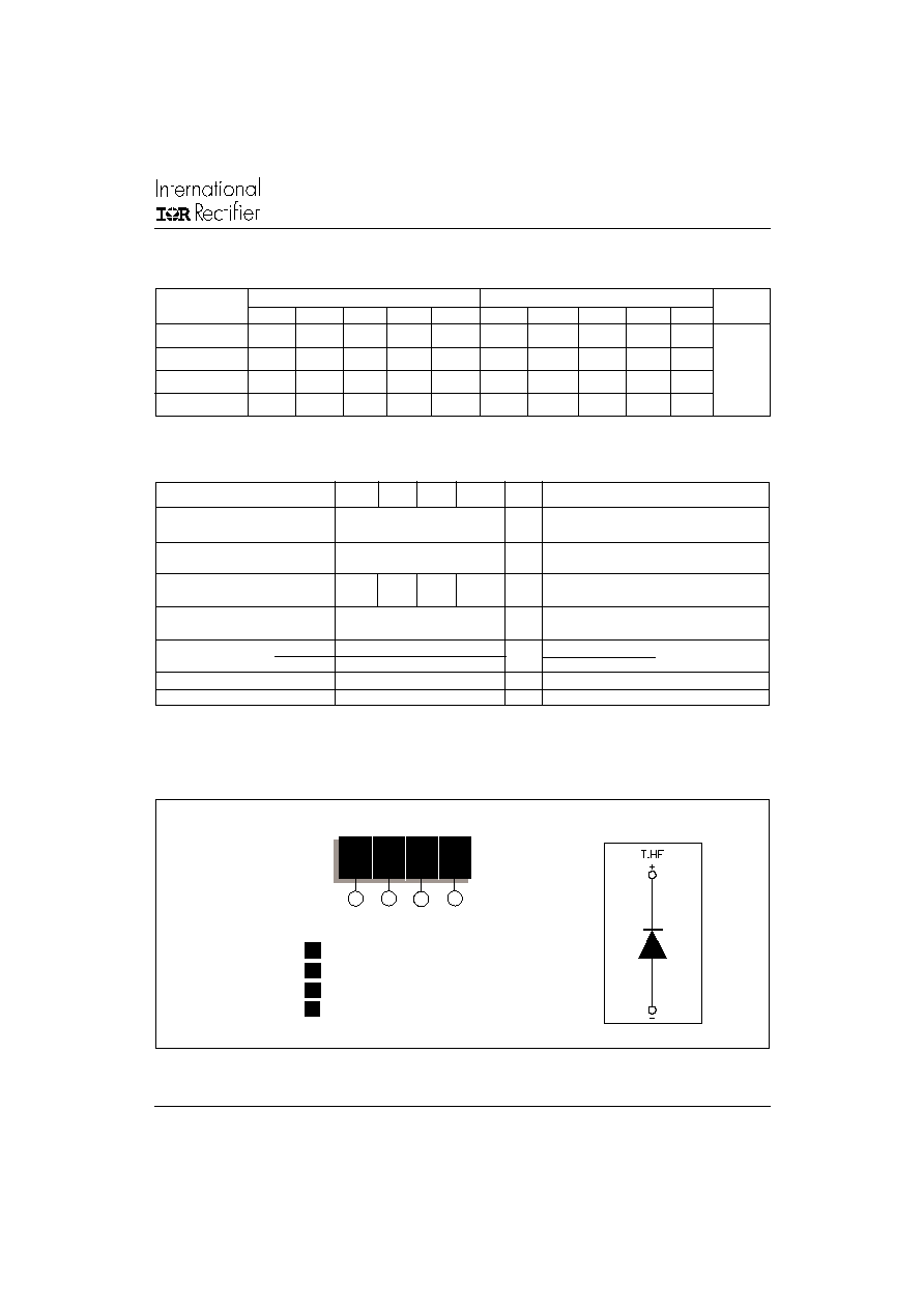
Type number
Voltage
V
RRM
, maximum repetitive
V
RSM
, maximum non-repetitive
I
RRM
max.
Code
peak reverse voltage
peak reverse voltage
T
J
= @ 25�C
V
V
� A
10
100
150
T40HF..
20
200
300
T70HF..
40
400
500
T85HF..
60
600
700
100
T110HF..
80
800
900
100
1000
1100
120
1200
1300
I
RRM
Max. peak reverse leakage
15
15
20
20
mA T
J
= 150
o
C
current
V
INS
RMS isolation voltage
3500
3500
3500
3500
V
50Hz, circuit to base, all terminals shorted
T
J
= 25
o
C , t = 1s
Voltage Ratings
ELECTRICAL SPECIFICATIONS
Blocking
Parameters
T40HF T70HF T85HF T110HF Units
Conditions
Forward Conduction
Parameters
T40HF T70HF T85HF T110HF Units
Conditions
T..HF Series
3
Bulletin I27106 rev. B 02/02
www.irf.com
(2) A mounting compound is recommended and the torque should be rechecked after a period of about 3 hours to allow for the spread
of the compound
Device Code
1
T
110
HF
120
Circuit configuration **
2
3
4
1
-
Module type
2
-
Current rating
3
-
Circuit configuration **
4
-
Voltage code : code x 10 = V
RRM
Ordering Information Table
Sinusoidal conduction @ T
J
max.
Rectangular conduction @ T
J
max.
Devices
Units
180
o
120
o
90
o
60
o
30
o
180
o
120
o
90
o
60
o
30
o
T40HF
0.12
0.14
0.18
0.27
0.46
0.09
0.15
0.20
0.28
0.46
K/W
T70HF
0.09
0.11
0.14
0.20
0.35
0.07
0.11
0.15
0.21
0.35
T85HF
0.08
0.09
0.12
0.18
0.31
0.06
0.10
0.13
0.19
0.31
T110HF
0.05
0.07
0.09
0.14
0.23
0.05
0.08
0.10
0.15
0.24
R Conduction (per Junction)
(The following table shows the increment of thermal resistance R
thJC
when devices operate at different conduction angles than DC)
Parameters
T40HF T70HF T85HF T110HF
Units
Conditions
T
J
Max. junction operating
-40 to 150
�C
temperature range
T
stg
Max. storage temperature
-40 to 150
�C
range
R
thJC
Max. thermal resistance,
1.36
0.69
0.62
0.47
K/W
DC operation, per junction
junction to case
R
thCS
Max. thermal resistance,
0.2
K/W
Mounting surface smooth, flat and greased
case to heatsink
T
Mounting
to heatsink
1.3 � 10%
Nm
M3.5 mounting screws (2)
torque � 10%
terminals
3 � 10%
M5 screw terminals
wt
Approximate weight
54
g
See outline table
Case style
D-56
T type
Thermal and Mechanical Specifications
non lubricated
threads
T..HF Series
4
Bulletin I27106 rev. B 02/02
www.irf.com
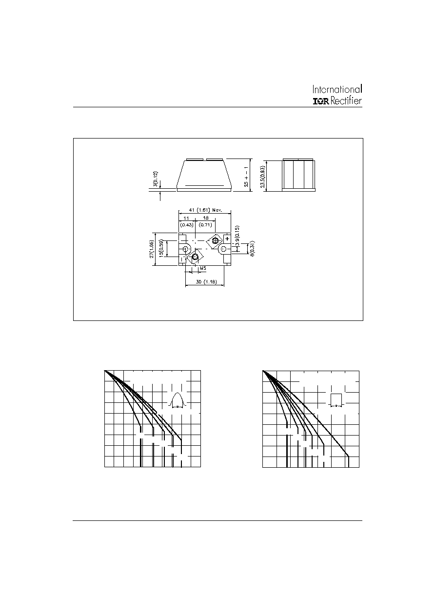
All dimensions in millimeters (inches)
Outline Table
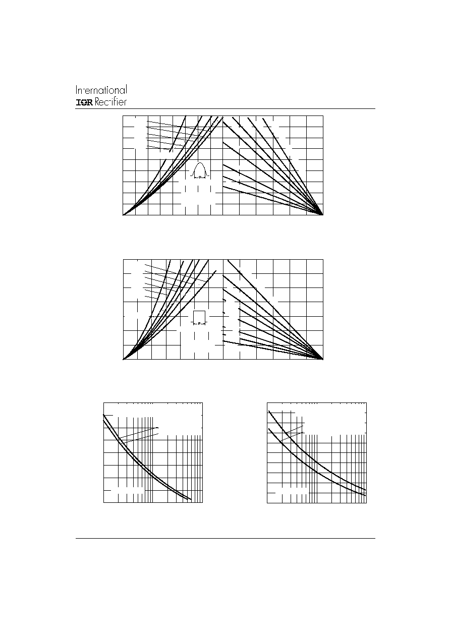
Fig. 1 - Current Ratings Characteristics
Fig. 2 - Current Ratings Characteristics
60
70
80
90
100
110
120
130
140
150
0
10
20
30
40
50
30
60
90
120
180
Ma
x
i
mu
m
A
l
l
o
w
a
b
l
e
C
a
s
e
T
e
mp
e
r
a
t
u
r
e
(
C
)
C ond uc tio n A ng le
A verage Fo rw a rd C urrent (A )
T40HF.. Series
R (DC ) = 1.36 K/W
thJC
60
70
80
90
100
110
120
130
140
150
0
10
20
30
40
50
60
70
D C
3 0
6 0
90
1 2 0
1 80
M
a
x
i
m
u
m
A
l
l
o
w
a
b
l
e
C
a
s
e
T
e
mp
e
r
a
t
u
r
e
(
C
)
C o nd uc tio n P e rio d
A v era g e Fo rw a rd C urrent (A )
T40H F.. Serie s
R (D C ) = 1 .36 K /W
th JC
T..HF Series
5
Bulletin I27106 rev. B 02/02
www.irf.com
Fig. 3 - Forward Power Loss Characteristics
Fig. 4 - Forward Power Loss Characteristics
Fig. 5 - Maximum Non-Repetitive Surge Current
Fig. 6 - Maximum Non-Repetitive Surge Current
0
25
50
75
100
125
150
M a xim u m A llo w ab le A m bie n t Te m p e ra tu re ( C )
R
=
0
.5
K
/W
-
D
e
lta
R
th
SA
1 K
/W
1.5
K
/W
2 K
/W
3 K
/W
5 K
/W
7 K/
W
1 0 K /W
0
5
10
15
20
25
30
35
40
45
0
5
10
15
20
25
30
35
40
A verag e Fo rw a rd C urrent (A )
RM S Lim it
M
a
x
i
mu
m
A
v
e
r
a
g
e
F
o
r
w
a
r
d
P
o
w
e
r
L
o
s
s
(
W
)
C o nd uc tio n A ng le
180
120
9 0
6 0
3 0
T40H F.. Series
T = 150 C
J
0
25
50
75
100
125
150
M ax im um A llow a ble A m bie n t Te m p e ra ture ( C )
10 K/W
5 K/W
2 K
/W
1.5
K
/W
1 K
/W
R
=
0
.5
K
/W
- D
e
lta
R
th
SA
7 K /W
3 K
/W
0
10
20
30
40
50
60
70
0
10
20
30
40
50
60
70
D C
180
120
90
60
30
RM S Lim it
C o nd uc tio n P e rio d
A verage Fo rw a rd C urrent (A )
M
a
x
i
m
u
m
A
v
e
r
a
g
e
F
o
r
w
a
r
d
P
o
w
e
r
L
o
ss
(
W
)
T40 HF.. Series
T = 1 50 C
J
150
200
250
300
350
400
450
500
550
1
10
100
P
e
a
k
H
a
l
f
S
i
n
e
W
a
v
e
F
o
r
w
ar
d
C
u
r
r
e
n
t
(
A
)
Num ber O f Equa l Amp litude H alf Cycle Cu rrent Pulses (N)
Initial T = 150 C
@ 60 H z 0.0083 s
@ 50 H z 0.0100 s
A t A ny Ra te d Lo a d C o nd itio n A nd W ith
Ra ted V A p p lied Fo llo w in g Su rg e .
J
RR M
T40HF.. Series
100
150
200
250
300
350
400
450
500
550
600
0.01
0.1
1
P
e
ak
Ha
l
f
S
i
n
e
Wav
e
F
o
r
w
a
r
d
Cu
r
r
e
n
t (
A
)
Pulse Tra in D uration (s)
M axim um N o n Re p etitive Surg e C urrent
T40HF.. Series
Initial T = 150 C
N o Vo ltage Reapp lied
Rated V Reapp lied
R R M
Versus Pulse Train Duratio n.
J