 | –≠–ª–µ–∫—Ç—Ä–æ–Ω–Ω—ã–π –∫–æ–º–ø–æ–Ω–µ–Ω—Ç: IS22C011 | –°–∫–∞—á–∞—Ç—å:  PDF PDF  ZIP ZIP |

ISSI
Æ
IS22C011
Integrated Silicon Solution, Inc.
1
VP001-1
I
10/01/98
ISSI reserves the right to make changes to its products at any time without notice in order to improve design and supply the best possible product. We assume no responsibility for any errors which
may appear in this publication. © Copyright 1998, Integrated Silicon Solution, Inc.
IS22C011
8 to 12 SEC INSTANT
VOICE ROM
ISSI
Æ
FEATURES
∑ Voice length at:
≠ 8 KHz sampling is 8 seconds
≠ 6 KHz sampling is 10 seconds
≠ 5 KHz sampling is 12.8 seconds
∑ Four trigger pins, S1 to S4 for eight sections
∑ SBT pin play-all or sequential play-all
∑ 15 ms debounce suitable for CDs
∑ IRP interrupt pin stops playback at once
∑ STP stop pulse comes out after playback
∑ BUSY signal for CPU control
∑ Two LEDs flash at 3 Hz interval
∑ 2.4V to 6V single power supply operation
∑ Low standby current (<5
µ
A at 3V)
∑ Auto power-down
∑ Built-in oscillator, D/A converter, EPROM
∑ ADPCM data compression
∑ Optional pop noise elimination function
∑ C
OUT
pin drives speaker with a transistor
∑ Development tools support
∑ V
OUT1
and V
OUT2
drives buzzer directly
∑ Sampling rate determined by external resistor
∑ Holdable and unholdable triggering option
∑ Industrial temperature available
GENERAL DESCRIPTION
The IS22C011 is a high-quality voice synthesizer
with capacity from 8 to 12 seconds. A proprietary
ADPCM algorithm is used. The audio message is
stored in a 256K bit on-chip one-time programmable
memory.
The IS22C011 eliminates the need for complicated
circuitry in voice playback but still achieves high voice
quality. Sounds such as human speech, animal
sounds, musical sounds, and even special effects
can be synthesized. Devices can be cascaded to
achieve longer voice duration. Two devices can be
configured in parallel in order to achieve signal mix-
ing without an external mixer so speech can be mixed
with background music each from one of two different
chips.
The instant programming nature of the IS22C011
gives a very short turn around time free of NRE
charges usually required with conventional voice
ROMs. Users now can add a voice synthesis function
as an additional feature to their products even when
production volume is small. As a result, initial invest-
ment is minimal and the risk in the product develop-
ment phase is reduced.
The IS22C011 provides wide voltage operating range
from 2.4V to 6.0V. A pair of PWM output pins, V
OUT1
and V
OUT2,
provide direct drive to a buzzer. Voice
quality is comparable to a speaker output and power
consumption is much lower. This facilitates button
battery applications such as greeting cards.
A current output pin, C
OUT
, enables the device to
drive a speaker through a low cost NPN transistor. No
complex filtering or amplifier circuit is needed. An
automatic ramp-down function eliminates undesired
noise at the end of playback.
Up to eight sections are available and accessible
through the S1 to S4 trigger pins. The SBT trigger pin
can be programmed to playback all eight sections or
sequentially from section 1 to 8. An interrupt pin
(IRP), stop pulse (STP) or BUSY signals provide
handshaking with
µ
P or other IS22C011 devices. All
trigger pins give 15 ms debounce time and are ideal
for CDS applications. Two LED drivers are available,
flashing on and off approximately at 3 Hz. The inter-
nal voltage compensation oscillator requires only
one external resistor. Different sampling frequencies
are determined by the external oscillator resistor
value.
OCTOBER 1998

ISSI
Æ
IS22C011
2
Integrated Silicon Solution, Inc.
VP001-1
I
10/01/98
Programmable Options
The IS22C011 provides different control functions for
user specified applications. They include:
∑
Non-sequence or Sequence play-all
∑
Unholdable or Holdable trigger
∑
STOP or BUSY signal selection
∑
Automatic ramp-down or no ramp-down
OSCILLATOR
OSC
CLOCK
GENERATOR
CONTROL
LOGIC
S1
S2
S3
S4
SBT
IRP
LED
DRIVER
LED1
LED2
STP/BUSY
POP NOISE
REDUCTION
ADDRESS
SEQUENCER
EPROM
ADPCM
DECODER
BUZZER
BUFFER
D/A
C
OUT
V
OUT1
V
OUT2
GND
VCC
BLOCK DIAGRAM
SEGMENT DECODE
1
2
3
4
5
6
7
8
S1
H
L
L
L
H
L
L
H
S2
L
H
L
L
H
H
L
L
S3
L
L
H
L
L
H
H
L
S4
L
L
L
H
L
L
H
H
3.5
3.0
2.5
2.0
1.5
1.0
0.5
0
5
6
7
8
9
10
SAMPLE FREQUENCY (KHz)
Typical Value, Vcc = 4.5V
R
OSC
(M
)
11 12 13 14 15
SAMPLE FREQUENCY

ISSI
Æ
IS22C011
Integrated Silicon Solution, Inc.
3
VP001-1
I
10/01/98
PIN CONFIGURATIONS
16-Pin DIP and SOP
PIN DESCRIPTIONS
LED1
Drives First LED Flash at 3 Hz
V
OUT1
PWM Audio Signal Output for Buzzer
STP/BUSY
Generate Busy Signal or 30 ms Pulse after Voice
Playback
GND
Ground
V
OUT2
Compliment PWM Audio Signal Output for Buzzer
LED2
Drives Second LED Flash at 3 Hz
C
OUT
Current Output from Internal DAC for Speaker
Playback
OSC
Oscillator Resistor Pin to Control Sampling
Frequency
V
PP
Program Power Supply, No Connect When Voice
Playback
S1-S4
Input Switches, Internal Pull LOW, Active HIGH
SBT
One Key or Sequential Trigger, Internal Pull LOW,
Active HIGH
IRP
Interrupt to Stop Playback, Internal Pull LOW,
Active HIGH
Vcc
Power Supply Voltage
1
2
3
4
5
6
7
8
16
15
14
13
12
11
10
9
LED1
V
OUT1
V
OUT2
GND
STP/BUSY
LED2
C
OUT
OSC
IRP
SBT
S4
S3
V
CC
S2
S1
V
PP
BONDING DIAGRAM
12
13
11
(0,0)
X
Y
Note: Substrate must be connected to GND
Pad size = 95
µ
m x 95
µ
m
Die size = 2100
µ
m x 2550
µ
m
10
9
8
7
6
5
14
15
16
NC
2
1
3
4
BONDING PARAMETERS
Pin
Name
X
Y
1
LED1
2005
1584
2
V
OUT1
2005
1891
3
V
OUT2
2005
2139
4
GND
2005
2422
5
STP
86.25
2383
6
LED2
86.25
2130
7
C
OUT
86.25
1854
8
OSC
86.25
1368
9
V
PP
86.25
1005
10
S1
86.25
637
11
S2
86.25
355
12
Vcc
86.25
112
13
S3
2005
156
14
S4
2005
468
15
SBT
2005
775
16
IRP
2005
1038
Note: Programming requires connection to
pins 4, 5, 6, 8, 9, 12, 15, and 16.
ISSI
Æ
IS22C011
4
Integrated Silicon Solution, Inc.
VP001-1
I
10/01/98
DC CHARACTERISTICS
Symbol
Parameter Description
Test Conditions
Min.
Typ.
Max.
Unit
V
CC
Operating Voltage
2.4
3.0
6.0
V
V
IH
Input HIGH Voltage
Vcc = 3.0V
2.5
3.0
3.5
V
V
IL
Input LOW Voltage
Vcc = 2.0V
≠0.3
0
0.3
V
I
OH
V
OUT
HIGH Operating Current
Vcc = 3.0V, V
OUT
= 3.0V
--
≠12
--
mA
I
OL
V
OUT
LOW Operating Current
Vcc = 3.0V, V
OUT
= 0V
--
12
--
mA
I
CO
C
OUT
Operating Current
Vcc = 3.0V, V
COUT
= 0.7V
--
≠2
--
mA
I
STPH
STP HIGH Operating Current
Vcc = 3.0V, V
STP
= 3.0V
--
≠5
--
mA
I
STPL
STP LOW Operating Current
Vcc = 3.0V, V
STP
= 0V
--
5
--
mA
I
LED
LED Output Current
Vcc = 2.2V ≠ 6.0V
6
8
10
mA
I
SB
Standby Current
Vcc = 3.0V, I/O Open
--
1
5
µ
A
I
OP
Operating Current
Vcc = 3.0V, I/O Open
--
--
100
µ
A
F/F
Frequency Stability
1 ≠ F
OSC
(3.5V)/F
OSC
(3.0V)
--
--
5
%
AC SWITCHING CHARACTERISTICS
Symbol
Parameter Description
Typ.
Unit
t
DD
Debounce Delay
15
ms
t
ST
Stop Pulse Width
30
ms
ABSOLUTE MAXIMUM RATINGS
(1)
Symbol
Parameter
Value
Unit
V
TERM
Terminal Voltage with Respect to GND
≠0.5 to +7.0
V
T
BIAS
Temperature Under Bias
≠40 to +85
∞
C
T
STG
Storage Temperature
≠55 to +125
∞
C
Notes:
1. Stress greater than those listed under ABSOLUTE MAXIMUM RATINGS may cause permanent damage to the
device. This is a stress rating only and functional operation of the device at these or any other conditions above
those indicated in the operational sections of this specification is not implied. Exposure to absolute maximum
rating conditions for extended periods may affect reliability.
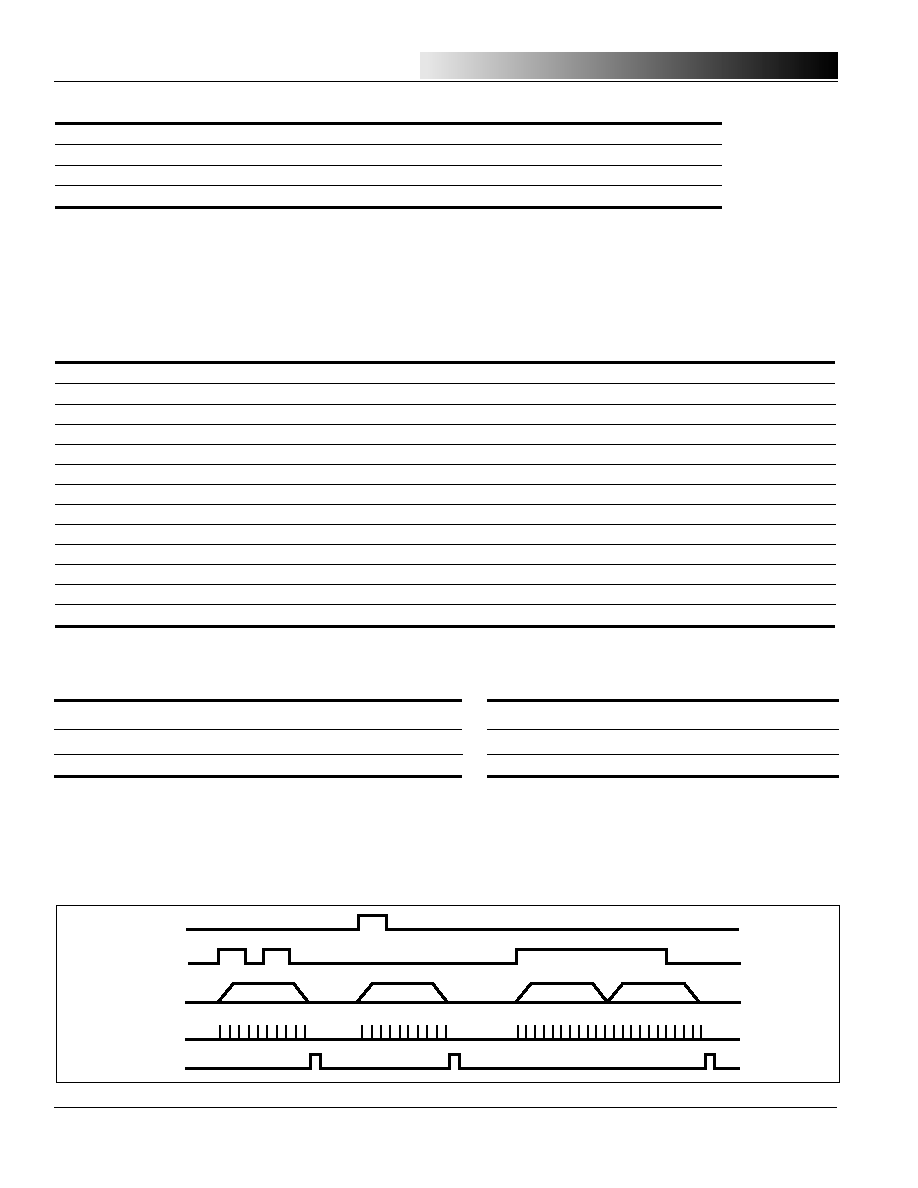
SWITCHING WAVEFORMS
S1 to S4 SEGMENT TRIGGERS. PULSE TRIGGERED.
a. Trigger is shorter than a phrase output
b. Trigger is longer than a phrase output
S1
Phrase 2
S2
C
OUT
LED
STP
Phrase 1
Phrase 2
Phrase 2
OPERATING RANGE
Range
Ambient Temp.
Vcc
Commercial
0
∞
C to +70
∞
C
2.4V to 6.0V
Industrial
≠40
∞
C to +85
∞
C
2.4V to 6.0V

ISSI
Æ
IS22C011
Integrated Silicon Solution, Inc.
5
VP001-1
I
10/01/98
SWITCHING WAVEFORMS
SINGLE BUTTON TRIGGER, NONSEQUENTIAL (SBT)
a. Pulse Triggered
b. Level Triggered
Phrase 1
SBT
C
OUT
Phrase 2
Phrase N
Phrase 1
Phrase N
Phrase 1
Phrase 1
SBT
C
OUT
Phrase 2
Phrase 1
Phrase N
Phrase 1
SINGLE BUTTON TRIGGER, SEQUENTIAL (SBT)
a. Pulse Triggered
b. Level Triggered
Phrase 1
SBT
C
OUT
Phrase 2
Phrase 2
Phrase 2
Phrase N
Phrase 1
Phrase 1
SBT
C
OUT
Phrase 2
Phrase 2
Phrase 2
Phrase N
Phrase 1
LEVEL TRIGGERED
a. Trigger is shorter than a phrase output
b. Trigger is longer than a phrase output
S1
Phrase 2
S2
C
OUT
LED
Phrase 1
Phrase 2
Phrase 2