 | –≠–ª–µ–∫—Ç—Ä–æ–Ω–Ω—ã–π –∫–æ–º–ø–æ–Ω–µ–Ω—Ç: 321100000 | –°–∫–∞—á–∞—Ç—å:  PDF PDF  ZIP ZIP |
N≠8
N
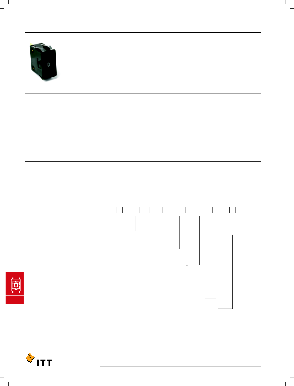
Thumbwheel & Pushwheel
C&K 3 Series
Thumbwheel Switches
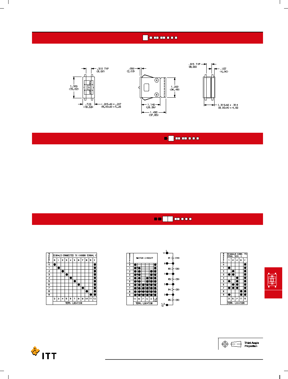
Dimensions are shown: Inch (mm)
Specifications and dimensions subject to change
www.ittcannon.com
Features/Benefits
∑
Most complete product offering in the industry
∑
Spacers available to fit most panel cutouts
∑
Front or rear mounting options
Typical Applications
∑
Test & measurement equipment
∑
Industrial equipment
∑
Computer devices
Specifications
CONTACT RATING:
CARRY: 1 AMP continuous.
SWITCH: 100 mA max.
OPERATING VOLTAGE: 50 mV to 28 V DC or 120 V AC.
ELECTRICAL LIFE: 100,000 actuations.
CONTACT RESISTANCE: Below 100 m
typ. initial @
2-4 V DC, 100 mA.
INSULATION RESISTANCE: 109
min.
DIELECTRIC STRENGTH: 500 Vrms min. @ sea level
between common terminal and any output.
OPERATING TEMPERATURE: -10∫C to 65∫C.
Materials
HOUSING: ABS plastic.
THUMBWHEEL: ABS plastic.
ROTOR CONTACTS: Precious metal on copper alloy.
STATOR CONTACTS: Hard gold over nickel over copper
on epoxy fiberglass.
NOTE: Specifications and materials listed above are for switches with standard options
For information on specific and custom switches, consult Customer Service Center.
* Note: All models listed are RoHS compliant. See Technical Data section of this catalog for
RoHS compliant and compatible definitions and specifications.
Build-A-Switch
To order, simply select desired option from each category and place in the appropriate box. Available options are shown and
described on pages N≠9 thru N≠12. For additional options not shown in catalog, consult Customer Service Center.
Consult factory for illumination availability.
Series
3
Thumbwheel switch
Number of Sections
0
Switch section
1
1 Switch section
2
2 Switch sections
3
3 Switch sections
4
4 Switch sections
5
5 Switch sections
6
6 Switch sections
7
7 Switch sections
8
8 Switch sections
9
More than 8
switch sections
Seal
0
No seal
1
Sealed contacts
2
Dust lens
3
Sealed contacts & dust lens
Function Code
11
Decimal, SP, 10 position
14
Resistor decade
21
BCD, 10 position
23
Complement of BCD, 10 position
27
BCD, 10 position
31
BCD, 10 position
71
BCH, 16 position
Terminations
0
Type 0
1
Type 1, extended type 0
N
Solder pins with .100" spacing**
P
Solder pins with .156" spacing**
9
Any combination
Color/Marking/Stops
0
Matte black body, gloss
black wheel,
white marking
Mounting Style
00
Snap-in, front mount
09
Snap-in, front mount*
10
Rear mount
19
Rear mount*
20
Rear mount
29
Rear mount*
*X9 mounting styles must be ordered with `0' number of sections.
** Note: Termination option N (RoHS compliant) replaced termination option 3 (Non-RoHS compliant).
Termination option P (RoHS compliant) replaced termination option B (Non-RoHS compliant).
C&K 3 Series
Thumbwheel Switches
SERIES
NUMBER OF SECTIONS
FUNCTION CODE
N
Thumbwheel & Pushwheel
Available Terminations: 0, 1, N
See fig. 1, page N-12.
Available Terminations: 1
See fig. 1, page N-12.
See fig. 1, page N-12.
Available Terminations: 0, 1, N
21
BCD 1-2-4-8; 10 POSITION
14
RESISTOR DECADE; 1-2-2-2-2 CODE
(RESISTORS NOT SUPPLIED)
11
DECIMAL≠1 POLE; 10 POSITION
9
More than 8 switch sections, specify on CONFIGURATION FORM, page N≠15 and consult Customer Service Center.
1-8
Number of switch sections in assembly, includes endplates.
0
Switch section only, no assembly. Blank bodies are considered sections; endplates are not sections.
Must be ordered with 09 or 19 mounting style options, see pages N≠10 and N≠11.
3
THUMBWHEEL SWITCHES
NOTE: Endplates and blank sections available separately, see pages N≠13 and N≠14.
NOTE: For terminal location diagram, see page N-12.
N≠9
Dimensions are shown: Inch (mm)
Specifications and dimensions subject to change
www.ittcannon.com

N≠10
N
Thumbwheel & Pushwheel
C&K 3 Series
Thumbwheel Switches
FUNCTION CODE
MOUNTING STYLE
Available Terminations: 0, 1, N
See fig. 1, page N-12.
Available Terminations: P
See fig. 2, page N-12.
See fig. 1, page N-12.
Available Terminations: 0, 1, N
Available Terminations: 0, 1, N
See fig. 1, page N-12.
N = Number of sections.
PANEL MOUNTING
09
SWITCH SECTION ONLY≠UNASSEMBLED WITHOUT ENDPLATES OR SPACERS
(Must be ordered with number of sections option "0", see Page N≠9.)
00
SWITCH ASSEMBLY W/ ENDPLATES≠.315 (8,00) SECTION PITCH
Type 0 Snap-In Front Mount
23
COMPLEMENT OF BCD 1-2-4-8;
10 POSITION
71
BINARY CODED HEXADECIMAL,
16 POSITION
31
BCD 1-2-4-8; 10 POSITION
27
BCD 1-2-4-8; 10 POSITION
NOTE: For terminal location diagram, see page N≠12.
NOTE: Endplates, blank sections, spacers
and assembly hardware available separately, see pages N≠13 and N≠14.
(.315 x N) + .326
(8,00 x N) + (8,28)
00
DIM. `A'
MOUNTING
STYLE
N = Number of sections.
Recommended panel thickness:
0.46-.125
(1,16-3,18)
Dimensions are shown: Inch (mm)
Specifications and dimensions subject to change
www.ittcannon.com

C&K 3 Series
Thumbwheel Switches
MOUNTING STYLE
N
Thumbwheel & Pushwheel
N = Number of sections.
PANEL MOUNTING
Mtg. Holes
N = Number of sections.
(.350 x N) + .560
(8,89 x N) + (14,22)
(.350 x N) + .340
(8,89 x N) + (8,64)
10
DIM. `B'
DIM. `A'
MOUNTING
STYLE
N = Number of sections.
Recommended panel thickness:
0.46-.125
(1,16-3,18)
20
SWITCH ASSEMBLY W/ ENDPLATES≠.350 (8,89) SECTION PITCH
29
SWITCH SECTION ONLY≠UNASSEMBLED WITHOUT ENDPLATES OR SPACERS
(Must be ordered with number of sections option "0", see Page N≠9.)
19
SWITCH SECTION ONLY≠UNASSEMBLED WITHOUT ENDPLATES OR SPACERS
(Must be ordered with number of sections option "0", see Page N≠9.)
10
SWITCH ASSEMBLY W/ ENDPLATES≠.350 (8,89) SECTION PITCH
Type 1 Rear Mount
Type 2 Rear Mount
NOTE: Endplates, blank sections, spacers and
assembly hardware available separately, see pages N≠13 and N≠14.
N≠11
Dimensions are shown: Inch (mm)
Specifications and dimensions subject to change
www.ittcannon.com

N≠12
N
Thumbwheel & Pushwheel
COLOR/MARKING/STOPS
SEAL
Signal traces cut except for common(s).
FIG. 1
FIG. 2
9
ANY COMBINATION OF TERMINATION
CONFIGURATIONS OR SPECIAL TERMINATIONS.
P
SOLDER PINS WITH .156" SPACING
N
SOLDER PINS WITH .100" SPACING
1
TYPE 1, EXTENDED TYPE 0
0
TYPE 0
3
SEALED SWITCHING CONTACTS AND DUST LENS
2
DUST LENS. (Protects the character face of the wheel from abrasion and dirt).
1
SEALED SWITCHING CONTACTS. (Sealing is by means of an o-ring rotary seal and a cured-in-place elastomer gasket.
Switching contact area is protected from moisture, oil, and airborne contaminants.)
0
UNSEALED SWITCHING CONTACTS.
0
MATTE BLACK HOUSING (Gloss black wheel with white characters; no stops.)
PC Board 1/32" (0,79) thick.
NOTE: See function codes, pages N≠9 and N≠10, for signal locations.
NOTE: Stop pins are available separately, see page N≠14.
Dust Lens
NOTE: All terminal holes shown may not be present for all function codes, consult Customer Service Center.
Terminal connector available for termination options 0 & 1, see page N≠14.
Specify on configuration form, page N≠15
and consult Customer Service Center.
Terminal Location Numbers
C&K 3 Series
Thumbwheel Switches
TERMINATIONS
Dimensions are shown: Inch (mm)
Specifications and dimensions subject to change
www.ittcannon.com
NOTE: Termination option N (RoHS compliant) replaced termination option 3 (Non-RoHS compliant).
Termination option P (RoHS compliant) replaced termination option B (Non-RoHS compliant).