M
Switchlock
M≠34
Dimensions are shown: Inch (mm)
Specifications and dimensions subject to change
www.ittcannon.com
Models Available
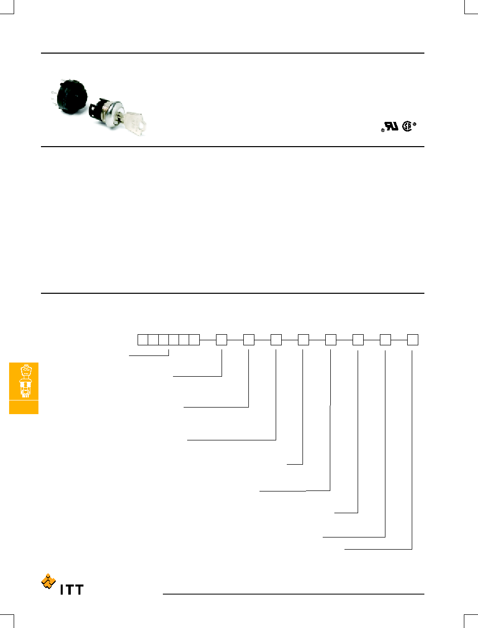
C&K A Series
4 & 5 Tumbler 1-4 Pole Switchlocks
Features/Benefits
∑
Multi-pole and multi-position
∑
Shorting and non-shorting
contacts available
∑
Low level and power capability
∑
PCB mounting
Typical Applications
∑
Security alarm systems
∑
Medical equipment
∑
Computer servers
Specifications
CONTACT RATING: Q contact material: Switch-2.5 AMPS @
125 V AC; 350 mA @ 125 V DC (UL/CSA). Carry-5 AMPS
continuous. See page M-38 for additional ratings.
ELECTRICAL LIFE: 15,000 make-and-break cycles at full load up to
300,000 detent operations.
CONTACT RESISTANCE: Below 20 m
typ. initial @ 2-4 V DC,
100 mA, for both silver and gold plated contacts.
INSULATION RESISTANCE: 109
min.
DIELECTRIC STRENGTH: 1,000 Vrms min. @ sea level.
OPERATING TEMPERATURE: ≠30∫C to 85∫C.
INDEXING: 30∫: 2-4 positions, 45∫ or 90∫: 2-3 positions.
STATIC RESISTANCE: Anti-static models exceed 20 KV DC static
resistance @ sea level, lock body to terminals.
Materials
LOCK: Zinc alloy with stainless steel facing.
KEYS: Two nickel plated brass keys with code number.
SWITCH HOUSING: Glass filled 6/6 nylon (UL 94V-0).
MOVABLE CONTACT: Q contact material: Coin silver, silver plated.
See page M-38 for additional contact materials.
STATIONARY CONTACTS & TERMINALS: Q contact material: Brass,
silver plated. See page L-38 for additional contact materials.
MOUNTING NUT: Zinc alloy.
DRESS NUT: Brass, nickel plated.
LOCKING RING: 6/6 nylon (UL 94V-2).
TERMINAL SEAL: Epoxy.
NOTE:
Any models supplied with Q or B contact material are RoHS compliant. For the latest
information regarding RoHS compliance, please go to: www.ittcannon.com/rohs.
NOTE: Specifications and materials listed above are for switchlocks with standard options.
For information on specific and custom switchlocks, consult Customer Service Center.
Build-A-Switch
To order, simply select desired option from each category and place in the appropriate box. Available options are shown and
described on pages M≠35 through M≠38. For additional options not shown in catalog, consult Customer Service Center.
Switch and lock Function
A21613
DP, 30∞, keypull pos. 1
A11413
SP, 90∞, keypull pos. 1
A31413
3P, 90∫, keypull pos. 1
A3141U
3P, 90∞, keypull pos. 1 & 2
A11513
SP, 45∞, keypull pos. 1
A31513
3P, 45∞, keypull pos. 1
A3151U
3P, 45∞, keypull pos. 1 & 3
A21582
DP, 45∫, keypull pos. 1
A11613
SP, 30∞, keypull p05. 1
A1161U
SP, 30∞, keypull pos. 1 & 4
A12112
SP, 45∞, keypull p05. 1
A42112
4P, 45∞, keypull pos. 1
Seal
NONE
No seal
E
Epoxy seal
Keying
2
Two nickel plated brass keys
Terminations
Z
Solder lug
C
PC Thru-hole
Contact Material
Q
Silver
B
Gold
Lock Type
A
4 Tumbler lock
G
5 Tumbler lock with anti-static switch
Y
4 Tumbler lock with anti-static switch
Lock Finish
2
Stainless steel facing
1
Nickel plated with
removable dress nut
8
Gloss black facing
Shorting/Non-Shorting
N
Non-shorting contacts
S
Shorting contacts
Mounting/Lock Style
N
With nut
R
With removable dress nut
M≠35
Dimensions are shown: Inch (mm)
Specifications and dimensions subject to change
www.ittcannon.com
M
Switchlock
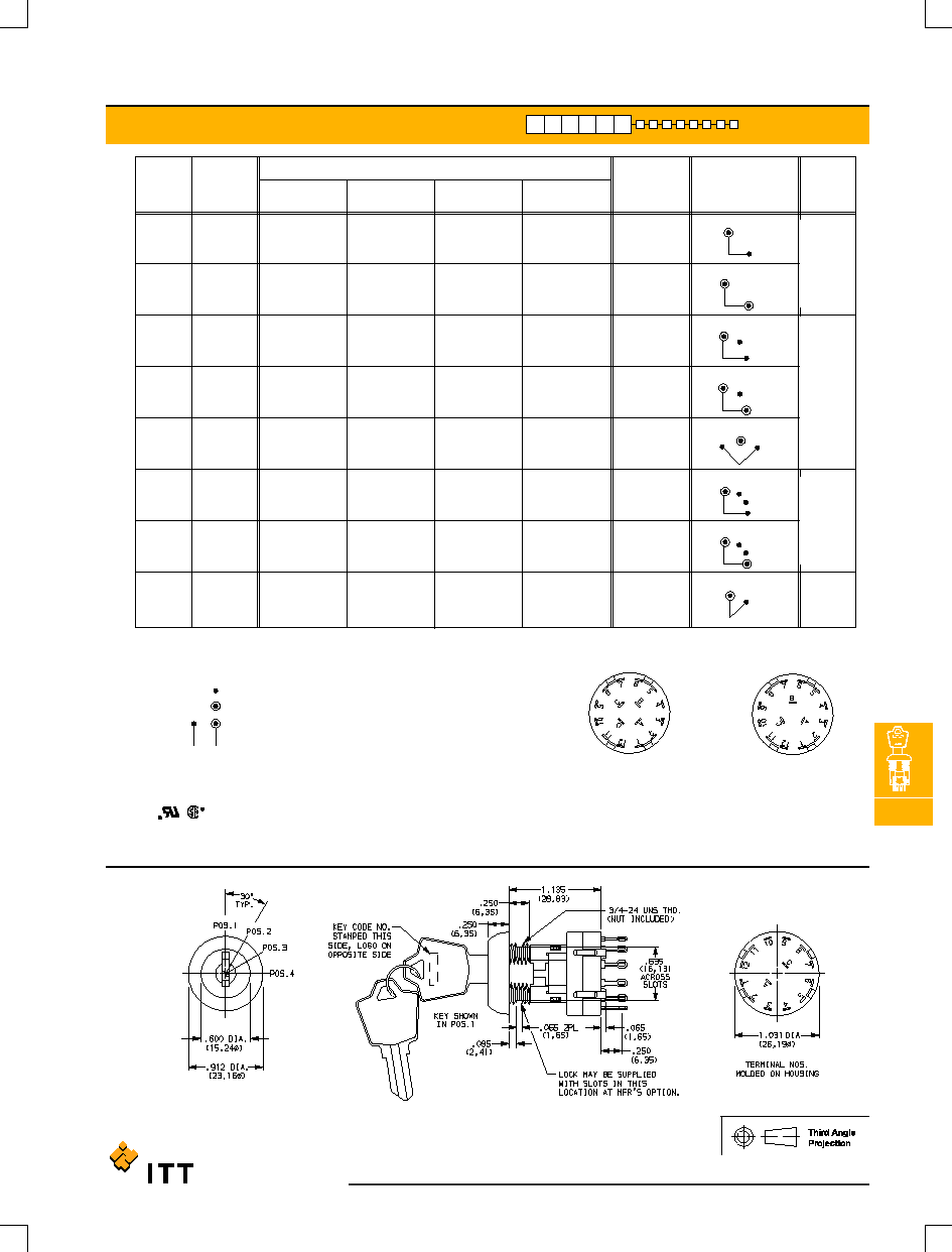
AX161X SWITCH FUNCTION
SHOWN
= Detent Positions (30∫ , 45∫ or 90∫ )
= Key pull possible in these positions.
= Stop Positions
LEGEND
3P MODEL
4P MODEL
SP MODEL (omit terminals B, C & D)
DP MODEL (omit terminals B & D)
TERMINAL NUMBERS
Terminal numbers molded on housing bottom.
4
POS. 1
2
3
4
POS. 1
2
3
2
POS. 1
2
POS. 1
POS. 1
2
3
POS. 1
2
3
POS. 1
2
3
POS. 1
2
*NOTE: Switchlock models A114XX, A115XX, A116XX and A12112 with `C'
terminations have additional terminal no. 8 as switch support only. This terminal is
not connected electrically inside switch.
All models
with all options when ordered with `Q' contact material.
AX14 models not available with `S' shorting contacts.
Part number shown: A116132Y2NZNQ
C&K A Series
4 & 5 Tumbler 1-4 Pole Switchlocks
SWITCH AND LOCK FUNCTION
45∫
Position 1
A-2
A-2, B-5, C-8, D-11
A-1
A-1, B-4, C-7, D-10
A12112
*
A42112
SP
4P
Positions 1 & 4
A-4
A-3
A-2
A-1
A1161U
*
SP
Position 1
A-4
A-4, C-10
A-3
A-3, C-9
A-2
A-2, C-8
A-1
A-1, C-7
A11613
*
A21613
SP
DP
Position 1
A-2, C-8
A-5, C-11
A-4, C-10
A21582
DP
Positions 1 & 3
A-4, B-8, C-12
A-2, B-6, C-10
A-1, B-5, C-9
A3151U
3P
Position 1
A-4
A-4, B-8, C-12
A-2
A-2, B-6, C-10
A-1
A-1, B-5, C-9
A11513
*
A31513
SP
3P
Positions 1 & 2
A-4, B-8, C-12
A-1, B-5, C-9
A3141U
3P
Position 1
A-4
A-4, B-8, C-12
A-1
A-1, B-5, C-9
A11413
*
A31413
SP
3P
INDEXING
LOCK
CONFIGURATION
KEY PULL
POSITIONS
CONNECTED TERMINALS
POS. 1
POS. 2
POS. 3
POS. 4
MODEL
NO.
NO.
POLES
90∫
30∫
45∫

M
Switchlock
M≠36
Dimensions are shown: Inch (mm)
Specifications and dimensions subject to change
www.ittcannon.com
C&K A Series
4 & 5 Tumbler 1-4 Pole Switchlocks
KEYING
LOCK TYPE
LOCK FINISH
SHORTING/NON-SHORTING
1.635 (41,52)
(4 TUMBLER)
1.733 (44,01)
(5 TUMBLER)
A126
.798
(20,26)
.775
(19,68)
N
NON-SHORTING CONTACTS (break-before-make)
S
SHORTING CONTACTS (make-before-break)
2
STAINLESS STEEL
1
NICKEL
8
GLOSS BLACK
G
5 TUMBLER LOCK WITH ANTI-STATIC SWITCH
Y
4 TUMBLER LOCK WITH ANTI-STATIC SWITCH
A
4 TUMBLER LOCK WITH REMOVABLE DRESS NUT
NO
YES
2 NICKEL PLATED BRASS KEYS
2
CODE NO.
ON LOCK
CODE NO.
ON KEY
KEYING OPTIONS
OPTION
CODE
NOTE: All orders keyed alike, standard. For more than one key code, replacement keys,
or other special features, consult Customer Service Center.
Key part number: 115140126
Not available with AX23 models.
Not available with AX14 models.
NOTE: For available option combinations, see page M-38.
NOTE: For available option combinations, see page M-38.
∑
Y
∑
A
∑
G
MOUNTING STYLES
N
R
LOCK
TYPES
AVAILABLE OPTION COMBINATIONS
∑
∑
∑
∑
8
∑
∑
∑
2
∑
∑
1
MOUNTING
STYLES
N
R
LOCK TYPES
G
A
Y
FINISH
OPTIONS
AVAILABLE OPTION COMBINATIONS
NOTE: Key head shape subject to change without notice.

M≠37
Dimensions are shown: Inch (mm)
Specifications and dimensions subject to change
www.ittcannon.com
M
Switchlock
C&K A Series
4 & 5 Tumbler 1-4 Pole Switchlocks
TERMINATIONS
MOUNTING/LOCK STYLE
PANEL MOUNTING
1.036
(26,31)
.270
(6,68)
PANEL MOUNTING
3P MODEL
4P MODEL
PC MOUNTING
R
REMOVABLE DRESS NUT
N
WITH NUT
Z
SOLDER LUG
C
PC THRU-HOLE
TYPICAL INSTALLATION
Install hex nut with enough clearance to allow for dress nut
and panel. Place switch through cutout in rear of panel.
Install and tighten dress nut by hand, then tighten hex nut.
Always tighten assembly with back of panel hex nut to
avoid damaging front of panel.
Nut part number: 175050700
SP MODEL (omit terminals B, C ,D)
DP MODEL (omit terminals B & D)

M
Switchlock
M≠38
Dimensions are shown: Inch (mm)
Specifications and dimensions subject to change
www.ittcannon.com
CONTACT MATERIAL
SEAL
AVAILABLE HARDWARE
E
EPOXY SEAL
NONE
NO SEAL
Switch and Lock Assembly Instructions
Mounting Information (All Models)
1. Place lock assembly in mounting hole on panel,
secure with mounting nut.
2. Align keying tab on switch assembly with keying
slot on lock assembly.
3. Snap assemblies together.
4. Switch installation is permanent. Switch cannot
be removed from lock after assembly. Attempting
to separate switch and lock may cause damage
to switchlock.
1
MOVABLE CONTACT: Copper alloy, with gold plate over nickel plate.
STATIONARY CONTACTS & TERMINALS: Brass, with gold plate over nickel plate.
2
MOVABLE CONTACT: Coin silver, silver plated.
STATIONARY CONTACTS & TERMINALS: Brass, silver plated (standard with all
termination options).
All models
with all options when ordered with `Q' contact material.
Key Code: A126
4 TUMBLER
PART NO. (ONE KEY)
115140126
Material: Brass
Finish: Nickel plate
Key Code: D001
5 TUMBLER
PART NO. (ONE KEY)
115441001
Material: Brass
Finish: Nickel plate
.215 (5,46) max.
.125 (3,18) max.
R
.195 (4,95) max.
.105 (2,67) max.
N
PANEL THICKNESS
A & Y LOCK TYPES
G LOCK TYPES
MOUNTING
STYLES
∑
∑
∑
R
∑
∑
∑
∑
N
LOCK TYPES
G
A
Y
LOCK FINISHES
1
2
8
MOUNTING
STYLES
AVAILABLE OPTION COMBINATIONS
C&K A Series
4 & 5 Tumbler 1-4 Pole Switchlocks
MOUNTING/LOCK STYLE
* Note: See Technical Data section of this catalog for RoHS compliant and compatible
definitions and specifications.
CONTACT AND
OPTION
CODE
TERMINAL MATERIAL
RATING
Q
SWITCH-2.5 AMPS @ 125 V AC; 350 mA @ 125 V DC (UL/CSA).
LOW LEVEL/DRY CIRCUIT
B
SILVER
2
POWER
0.4 VA MAX. @ 20 V AC or DC MAX.
RoHS
COMPLIANT*
RoHS
COMPATIBLE *
YES
YES
YES
YES
GOLD
1
CARRY-5 AMPS CONTINUOUS.