Insulator
Thermoplastic UL94V-0 rated
Contacts
Copper alloy
Contact Finish
Gold over nickel
PC tail plating
Tin lead (2µ min.)
Mechanical life
30,000 cycles min
Card insertion force
10 N max
Card extraction force
1 N min /10 N max
Contact force
0.20 N min / 0.60 N max
Vibration
Frequency 10 to 500 Hz. Acceleration 50m/s
2
Duration 6 hours - amplitude 0,35 mm
Max electrical discontinuity 1µs
Shock
Peak value 500 m/s
2
≠ Duration 11 ms
3 shocks in each direction of each axis
Max electrical discontinuity 1 µs
Insulation resistance
1,000 M
min
Resistance
100 m
max
Current rating
10 µA min / 1 A max
Dielectric strength
750 Vrms min
Card detection switch
Normally closed
Contact resistance
100m
max
Dielectric strength
250 Vrms min
Current rating
1 mA min / 10 mA max
Maximum power
0.2 VA
Operating temperature
-20∞C to +70∞C
Soldering temperature
Wave: 260∞C / 5 seconds
Damp heat
IEC 512 test number 11c (10 days)
Salt mist
IEC 512 test number 11f (96 hours)
30 per tray, 10 trays per box.
10
Dimensions are shown in mm
Dimensions subject to change
www.ittcannon.com
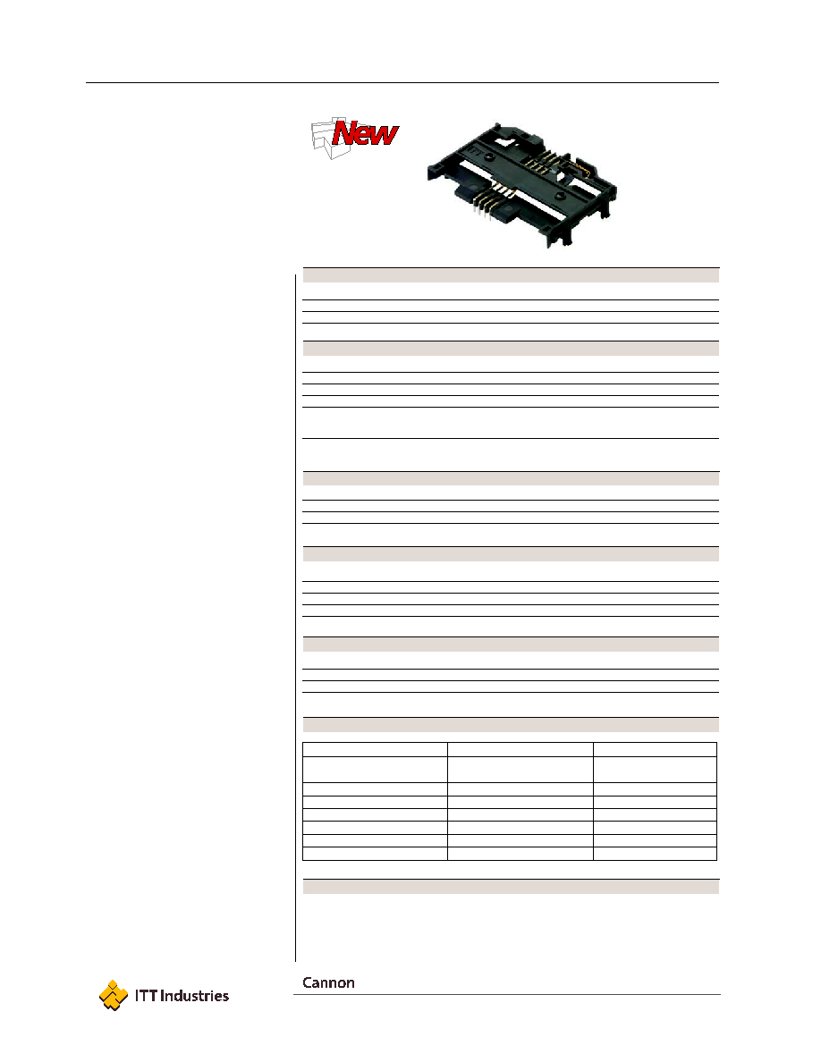
CCM01 MK III
CCM01 MK III connectors are intended
for applications such as pay TV, home
shopping and utility meters. Mainly
driven by the Set Top Box market for
payment and/or deciphering.
Features
∑ Available in standard or reverse card
reading version, with direct PCB
soldering for reduced installation cost.
∑ Panel mount version comes with
improved noise reduction FPC, to
accommodate all front panel
configurations.
∑ Double sided version allows the
customer to insert the card chip up or
down for easier handling.
∑ Self cleaning card detection switch
(normally closed) is protected against
assembly mishandling.
∑ Available with 8 through hole contacts
specifically designed to reduce card
wear.
∑ A chamfer opening to the card entry
slot improves the card guidance into
the connector.
∑ Variable distance from lower card side
to PCB to level card slot with your front
panel design
∑ Easy insertion into PCB provided by
four half pegs and termination true
positioning insulator.
1
∑ Four snap in board locks to lower
stress on soldered terminals and
improve interconnect PCB retention.
∑ Thermoplastic UL 94 V-0 insulator
suitable for wave soldering only
∑ Designed to be compatible with:
NDS
EMVCo
1
Termination true positioning insulator not
designed on low profile version 3,9 mm
EMV
TM
is a trademark owned by EMVCoLLC.
Designation
Standard Version
Reverse Version
Distance from lower card
entrance & PCB
3,90 mm
CCM01-6101
CCM01-6201
6,75 mm
CCM01-6202
6,50 mm
CCM01-6105
8,00 mm
CCM01-6103
Panel Mount
CCM01-6301
CCM01-6302
Double Decker
CCM01-6402
CCM01-6403
Construction
Mechanical Data
Contact Electrical Data
Switch Electrical Data
Environmental Data
Packaging
Ordering Code
EMV
TM
compatible

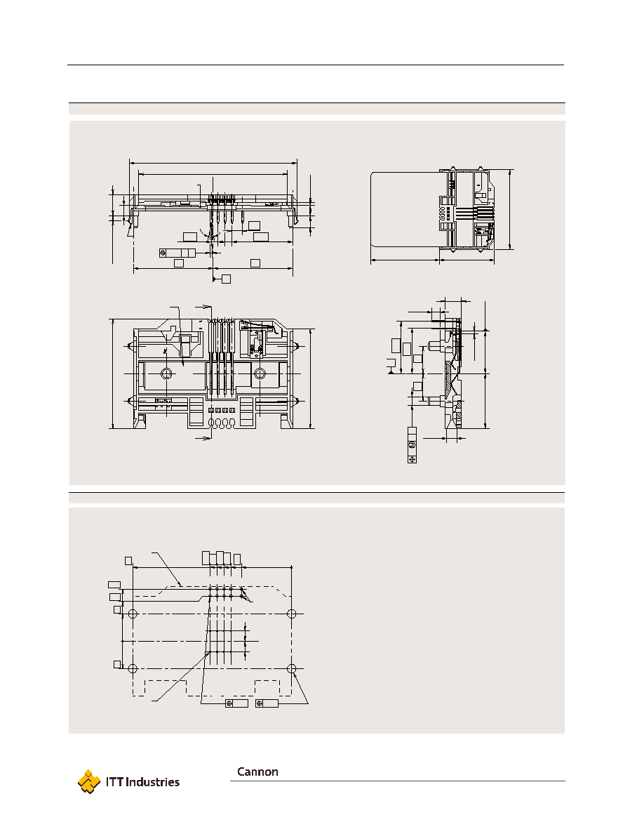
Dimensional Drawings
A
A
40
61,1
±
0,2
Card entry
54,2
+0,2
0
()
3,9
5,9
19,05
19,05
¯
3,1
0,4
A
B
22,12
3x 2,54
3,81
4,2
1,6 PCB
Thic
kness
Card entr
y
0,9
±
0,05
3,9
6,8
15,4
±
0,2
Card stop
0,75
±
0,25
20
3,7
±
0,2
0,7
0,6
A B
10
10
2,54
36,4
2,9
±
0,3
25∞
29
29
()
58
(
)
40
(
)
50,3
10x
Card entry
Designation & Date-Code area
4x
6101
XXXX
Pick and place area
¯8
Embossed
Channel
4 Snap feet
A-A
Card stop
6101
XXXX
A
B
PCB Layout
22,12
0
24,66
27,2
29,74
33,55
58
10
0
16,51
19,05
10
19,05
¯ 3,2
+0,1
0
¯1
+0,1
0
()
3,81
()
3,81
4x
10x
C1 C2 C3 C4 SW
C5 C6 C7 C8
SW
(Component side)
Card end travel
switch terminals
Plastic outline
Contact location according to
ISO 7816-2
¯0,1
¯0,1
CCM01 MK III
11
Dimensions are shown in mm
Dimensions subject to change
www.ittcannon.com
CCM01-6101
Unless otherwise stated, tolerances are ± 0,10 mm
Drawings shown for reference only. For other part numbers
please consult your local Cannon Customer Service Center.
CCM01-6101
12
Dimensions are shown in mm
Dimensions subject to change
www.ittcannon.com
Dimensional Drawings
A
A
10
10
¯
3,1
0,4
A
B
3,7
±
0,2
5,9
40
0,75
±
0,25
15,4
±
0,2
Card stop
20
22,12
4,2
1,6 PCB
Thic
kness
3,9
Card entr
y
0,9
±
0,05
61,1
±
0,2
Card entry
54,2 +0,2
0
()
3,9
7,8
3,81
36,4
2,9
±
0,3
19,05
16,51
0,7
0,6
A B
3x 2,54
25∞
29
29
()
58
( )
40
(
)
50,3
10x
Card entry
6201
XXXX
Designation & Date-Code area
4x
A-A
Card stop
Embossed
Channel
4 Snap feet
A
B
PCB Layout
18,31
0
22,12
24,66
27,2
29,74
58
10
0
10
16,51
19,05
()
3,81
()
3,81
¯3,2
+0,1
0
¯ 1
+0,1
0
4x
10x
C1
C2
C3
C4
SW
C5
C6
C7
C8
SW
(Component side)
Card end travel
switch terminals
Plastic outline
Contact location according to
ISO 7816-2
¯0,1
¯0,1
CCM01-6201
CCM01 MK III
Unless otherwise stated, tolerances are ± 0,10 mm
Drawings shown for reference only. For other part numbers
please consult your local Cannon Customer Service Center.
CCM01-6201