Dimensions are shown in mm
Dimensions subject to change
www.ittcannon.com
Contacts
Copper alloy
Plating
Contact area : Gold alloy inlay
Terminals: Tin lead (2µ min)
Moldings
High temp. thermoplastic UL 94V-0 rated
Spring
Stainless steel
Card detection switch actuator
Stainless steel
Number of Contacts
8
Mechanical life
500,000 cycles min
Card insertion force
10 N max
Card extraction force
1 N min / 10 N max
Contact force
0.25 N min / 0.5 N max
Card detection switch
0.8 N max for actuation (end travel switch
actuation force
actuates when card is 1,0 mm from
card stop) 1.8 N max for complete depression
Vibration
Frequency 10 to 500 Hz. Acceleration 50m/s
2
Duration 6 hours - amplitude 0,35 mm
Max electrical discontinuity 1µs
Shock
Peak value 500 m/s
2
≠ Duration 11 ms
3 shocks in each direction of each axis
Max electrical discontinuity 1 µs
Insulation resistance
1,000 M
min
Resistance 100
m
max
Current rating
10 µA min / 1 A max
Dielectric strength
750 Vrms min
Card detection switch
Normally open
Contact resistance
100 m
max
Dielectric strength
250 Vrms min
Current rating
1 mA min / 10 mA max
Maximum power
0.2 VA
Operating temperature
-40∞C to +85∞C
Soldering temperature
Temperature/time profile acc. to CECC00802
para. 6.1, Fig. 3 with peak temperature 250∞C
Damp heat
IEC 512 test number 11c (10 days)
Salt mist
IEC 512 test number 11f (96 hours)
Card detection switch
Sealed IP 54
30 per tray, 10 trays per box.
15
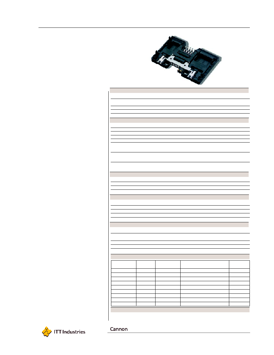
CCM02 MK II
The CCM02 MK II connectors with
landing contacts are dedicated for
applications where the reader usage is
high and the life span of the card is a
key consideration. A connector with
contacts which land on the card, rather
than slide over it, should be specified so
as to minimize card wear. The CCM02
has been redesigned to give an even
higher performance in a compact,
affordable package.
Features
∑ 500,000 card insertion cycles.
∑ The contacts do not touch the card
until it is almost fully inserted ≠ A
minimal wiping action removes any
non-conductive material.
∑ The connector has been designed to
give a positive indication once the
card has been fully inserted.
∑ The reduced size of the contact base
saves PCB space, making the
connector more stable during surface
mounting, and creates an air gap
between the contacts and card entry
slot, which reduces the risk of an
electrostatic transfer to the PCB.
∑ For added reliability, the integrated card
end-travel switch, which is normally
open, is sealed against dust and grit.
∑ By using an inlay finish in the contact
area, the life of the precious metal is
extended by more than 10 times that
of standard gold plating.
∑ The contact area is spooned to reduce
the risk of accidental (or deliberate)
damage and to optimize the electrical
connection with the card.
∑ Snap-locks underneath the molding
position and hold the connector on
the PCB, and give additional support
to the contact terminals.
∑ The plastic moldings are made from a
high temperature thermoplastic suited
for infrared and convection soldering
processes.
EMV
TM
is a trademark owned by EMVCoLLC.
Part Number
Number of
Termination
PCB
Packaging
Contacts
Tails Design
Locating
Multiple
CCM02-2503
8 Through
Hole
4 Board Lock (PCB 1.6 mm thick)
300
CCM02-2504
8 SMT
4 Board Lock (PCB 1.6 mm thick)
300
CCM02-2508
8
SMT
2 Pegs
300
CCM02-2511
8
Through Hole
4 Pegs
300
CCM02-2512
8
SMT
4 Pegs
300
CCM02-2758
8
SMT
2 Pegs (without cover)
300
CCM02-2763
8
SMT
4 Board Lock + 2 Pegs
300
CCM02-2765
8
Through Hole
4 Board Lock (PCB 1mm thick)
300
CCM02-2766
8
SMT
4 Board Lock (PCB 1mm thick)
300
Construction
Mechanical Data
Contact Electrical Data
Switch Electrical Data
Environmental Data
Ordering Code
Packaging
EMV
TM
compatible

Dimensions are shown in mm
Dimensions subject to change
www.ittcannon.com
16
Dimensional Drawings
A
A
(REF.)
50
38,5
52
¯0,2 A B
A
0,95
3,15
19,12
10
B
14
20
7,7
±
0,3
Card entry
4,15
±
0,3
5,75
15,7
1
±
0,25
(REF.)
38,5
(REF
.)
55,6
1
0,3
A
54,3
5x 2,54
0,65
1,8
4,3
±
0,2
0,2
±
0,15
13,8 (REF
.)
(REF
.)
3,2
0,8
0,8
1,6 PCB
Thic
kness
6,25
55,6
±
0,2
13,8
0 -0,3
3,2
+0,4 -0,2
13,8
0 -0,3
4 Snap
Feet
Embossed
Channel
10x
SEE DETAIL A
4x
2504
CCM02-
XXXX
Pick and place area
¯13
Designation & Date-Code area
"CCM02"
marking is optional
COUPE A-A
Card insertion
direction
Card stop
DETAIL A
PCB Layout
27,6
0 -0,6
3,2
20
1,8
10
19,12
21,66
24,2
26,74
29,28
31,82
0
25,3
1,7
52
3,81
3,81
¯ 3,2
+0,1
0
¯0,1
1,5
1,5
3,1
14
8,84
1,3
0,2
Card end travel
switch terminals
0,8 x 1
Contact foot area
0,8 x 1
C1 C2 C3 C4
C5 C6 C7 C8
SW SW
(Component side)
Contact location according to
ISO 7816-2
10x
4x
Pad
Plastic outline
CCM02-2504 (8 contacts SMT - 4 board lock)
CCM02-2504 (8 contacts SMT - 4 board lock)
CCM02 MK II
Unless otherwise stated, tolerances are ± 0,10 mm
Drawings shown for reference only. For other part
numbers please consult your local Cannon
Customer Service Center.