CGE High Power Connectors
HS-5 /1199
CGE
2
Dimensions are mm (inches)
Subject to changes
Contents
Introduction .......................................... 2
Connector Design .............................. 2
How to order ....................................... 3
Mateability ......................................... 3
Polarization ........................................... 3
Technical Data ...................................... 4
Panel Cut-Outs ..................................... 5
Connector Dimensions .......................... 6
Accessories ........................................... 9
Contacts and Tools ............................... 10
Product Safety Information .................. 11
Introduction
The Cannon CGE connectors are designed
to transmit very high current at low
voltage, as for example in the electrical
equipment of military land- and sea-borne
vehicles and in industrial applications. The
connectors meet the mating dimensions,
mechanical features and rear panel
installation requirements of VG 95234.
Ultraflexible shielded welding cables acc
to MTV 6145-005 are terminated to the
connectors.
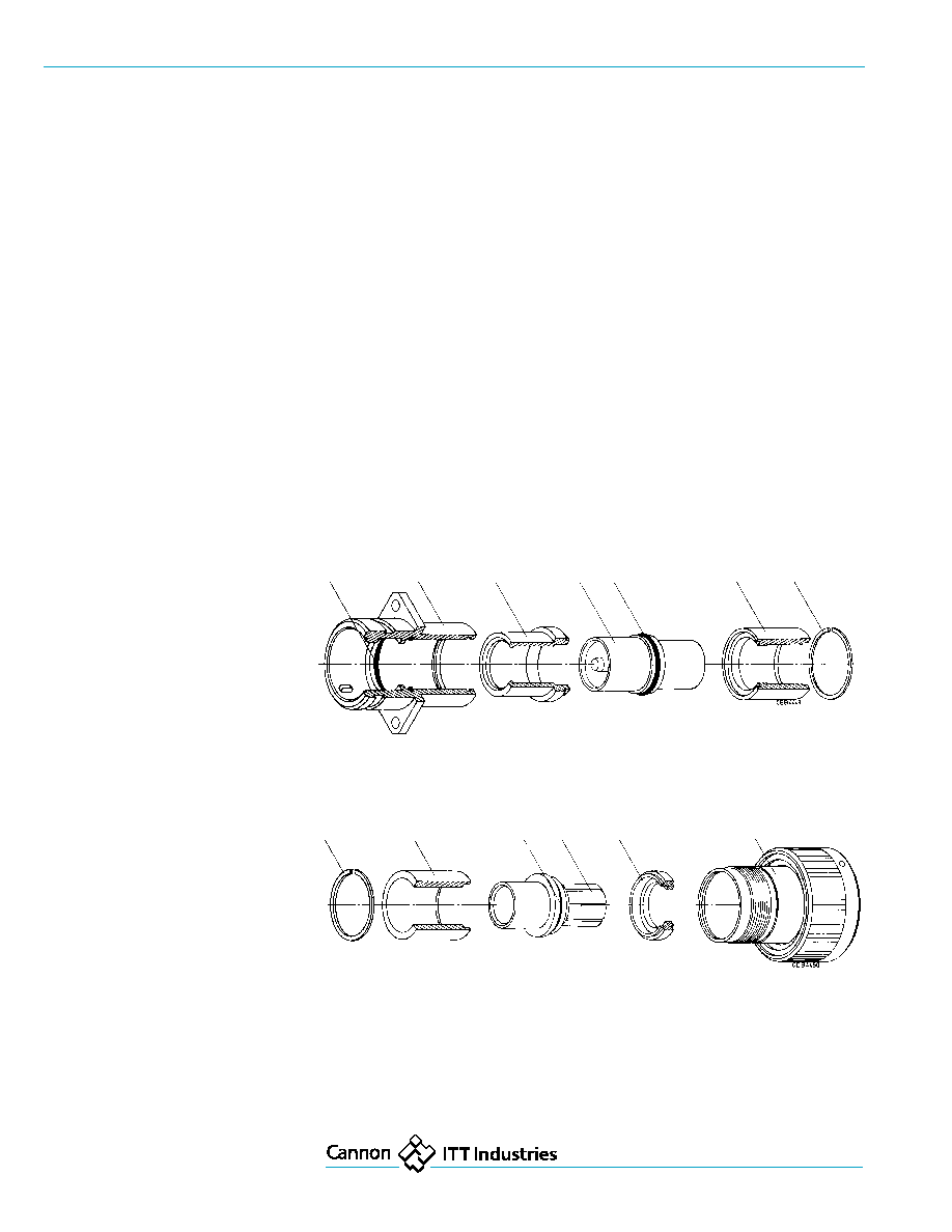
Connector Design
The high power connectors CGE feature
one contact in a two-piece rigid insulator.
The aluminum shell has a chromate finish
over cadmium. The operating temperature
ranges from ≠55 to 125
∞
C.
The contacts made of copper or a copper
alloy with hard silver finish are designed
for crimping or termination to solid copper
conductors with threaded bolts. The
mechanical durability is a minimum of 500
mating cycles. The crimp contacts accept
wires according to DIN 46438 (25 ≠ 240
mm
2
). Contact retention is achieved by the
two-piece insulator which is fixed to the
shell with a snap-in ring. This allows
unlimited exchange of the crimp contacts.
The bayonet coupling assures fast and
reliable mating and unmating. Audible
snap-in and colour-coded snap-in points
indicate positive mating. Plugs and
receptacles are waterproof in mated
condition up to 1 bar (35 feet of water).
O-Ring
Shell
Insulator
Cylindrical
O-Ring
Insulator
Spring ring
Contact
Contact
Contact
front side
rear side
Spring ring
Insulator
O-Ring
Spring
Insulator
Barrel assembly
Contact
contact
Contact
rear side
front side
Connector Design
CGE
3
CGE 6 E 32 H 24 F W B *
Series
Cannon Designation
Shell style
0 - wall mounting receptacle with flange
1 - cable connecting plug
2 - box mounting receptacle with flange
6 - straight plug
8 - plug 90
∞
9 - bulkhead
Class
E - environmental, JP07 acc to DIN 40050
Shell size
16 - 18 - 22 - 28 - 32
Contact arrangement
16H2 - shell size 16, 1 contact H2
18H5 - shell size 18, 1 contact H5
22H9 - shell size 22, 1 contact H9
28H15 - shell size 28, 1 contact H15
32H24 - shell size 32, 1 contact H24
Contact size
H2 - 25 mm
2
H5 - 50 mm
2
H15 - 150 mm
2
H24 - 240 mm
2
Contact type
F - spring contact
Z - cylindrical contact
Keyway polarization
W - 120
∞
Bayonet coupling
Modification
05 - through-holes in flange
03 - adapter for heat shrink boots, metric crimp contact
04 - rear panel mounting, threaded holes, metric crimp contact
04-05 - same as -04, however, with through-holes
14 - shielded version, metric crimp contact
16 - thread bolt termination, front panel mounting, O ring for sealing
between wall and receptacle (for CGE2EB only)
How to order
Mateability
Receptacles and cable connecting plugs mate with
Plugs, straight / 90
∞
CGE2E-B04, CGE-B-04-05
CGE6E-B-03
CGE2E-B-16
CGE6E-B-14
CGE0E-B-03, CGE-B-05-05
CGE8E-B-03
CGE1E-B-03
CGE8E-B-14
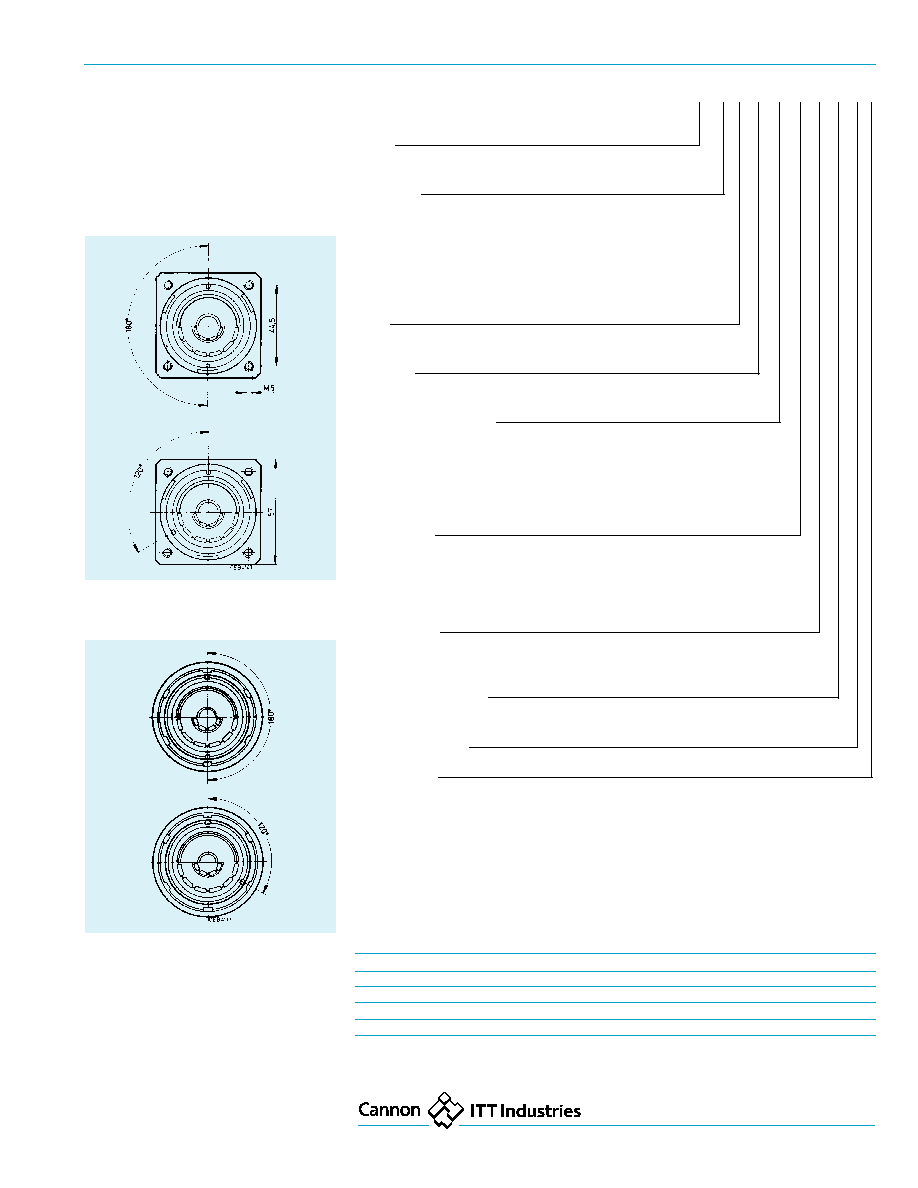
Polarization
To avoid mismating of identic connectors
the keyways of CGE connectors are avail-
able in two different positions:
Standard position
= 180
∞
Position W
= 120
∞
Keyway positions of receptacles
and cable connecting plugs
Keyway positions of straight and 90
∞
plugs
CGE
4
Dimensions are mm (inches)
Subject to changes
Technical Data
Admissible ambient temperature
≠55/125
∞
C
Class
JP07 acc to DIN 40050
Test pressure
1 bar overpressure
Test duration
12 h
Vibration
200 m/s
2
for 10 ≠ 2000 Hz
Mechanical durability
500 mating cycles
Coupling torque
in wired condition acc to VG95319, Part
2, Test No 5.8.2.
Shell size
max closing /
max opening
opening Nm
Nm
16
5,5
0,5
18
8,0
0,6
22
11,0
0,8
28
17,0
0,9
32
19,0
1,0
Contact retention
acc to VG 95319, Part 2, Test No 5.4.
Contact size
Test force N min
H2
100
H5
120
H9
140
H15
160
H24
200
Materials
Shell
Aluminum alloy
≠ Finish
Olive chromate over
cadmium
Insulator
PTFE
Contact
Copper or copper alloy
≠ Finish
Hard silver
O ring
FKM
Cables
The connectors are designed for ultraflexible welding cable acc to MTV 6145-005.
Shell size
Wire size
MTV 6145-005 designation
shielded
unshielded
16
25
MTV 6145-005 H001
MTV 6145-005 G001
18
50
MTV 6145-005 H002
MTV 6145-005 G002
22
95
MTV 6145-005 H003
MTV 6145-005 G003
28
150
MTV 6145-005 H004
MTV 6145-005 G004
32
240
MTV 6145-005 H005
MTV 6145-005 G005
When selecting a cable type please consider self-heating of cable at the maximum
operating voltage and the maximum ambient temperature (see page 5).
Electrical Data
Current rating
(A)
at 125
∞
C ambient temperature
Shell size
16
18
22
28
32
Contact size
H2
H5
H9
H15
H24
Max Current rating (A)
225
350
570
750
950
Max Short-time load,
appr 0,5 ≠ 1 sec (A)
750
1000
2000
3000
5000
Air and creepage paths
Air path
3 mm min
Creepage path
5 mm min
Insulator resistance
min 5000 MOhm
Contact resistance
(mOhm max)
Contact size
H2
H5
H9
H15
H24
Contact resistance
0,6
0,3
0,15
0,1
0,07

CGE
5
Cable Data
Approx. values for cable self-heating
Wire size
Max admissible
Approx over-temperature due to current load:
T in
∞
C
mm
2
operating voltage
1/3 of max admissible
2/2 of max admissible
max admissible
operating voltage
operating voltage
operating voltage
25
250
35
52
95
50
300
15
25
55
95
500
10
33
70
150
600
5
23
60
240
1000
8
30
75
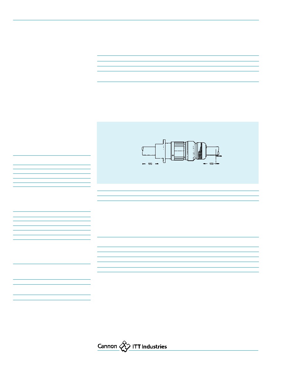
Cable designation
Shell
Wire size
Straight plug
Plug 90
∞
size
mm
2
a
b max
c max
d
+/≠10,5
e1
+/≠1,0
f1
+/≠1,0
e2
+/≠1,0
f2
+/≠1,0
MTV6145-005+001
16
25
7,5
+/≠0,5
13,5
10,2
14,0
31,0
46,0
-
-
MTV6145-005+001
18
50
11,0
+/≠0,5
18,0
14,3
15,0
31,0
46,0
-
-
MTV6145-005+001
22
95
16,0
+/≠0,5
23,5
19,7
20,5
42,0
57,0
20,0
35,0
MTV6145-005+001
28
150
20,5
+/≠0,5
30,0
25,4
30,0
-
-
25,0
40,0
MTV6145-005+001
32
240
26,5
+/≠0,5
36,0
32,5
30,0
54,0
69,0
25,0
40,0
Panel Cut-Outs
Panel cut-outs for rear and front panel
mounting of receptacles
Shell size
Receptacles, rear panel mounting
Receptacles, front panel mounting
CGE0E-B-03/14
CGE2E-B-16
CGE2E-B-04
H13
H12
H13
H12
c
+0,15
d
+0,15
d
±
0,15
c
thread
d
c
±
0,15
16
4,5
27,7
24,6
4,5
M4
22,5
24,6
18
4,5
31,1
27,0
4,5
M4
27,4
27,0
22
4,5
37,8
31,8
4,5
M4
33,7
31,8
28
5,5
47,1
39,7
4,5
M4
43,5
39,7
32
5,5
53,8
44,5
4,5
M4
49,7
44,5
Outer jacket
Shielding braid, tinned
Inner jacked
Copper conductor
Cable Dimensions
CGE
6
Dimensions are mm (inches)
Subject to changes
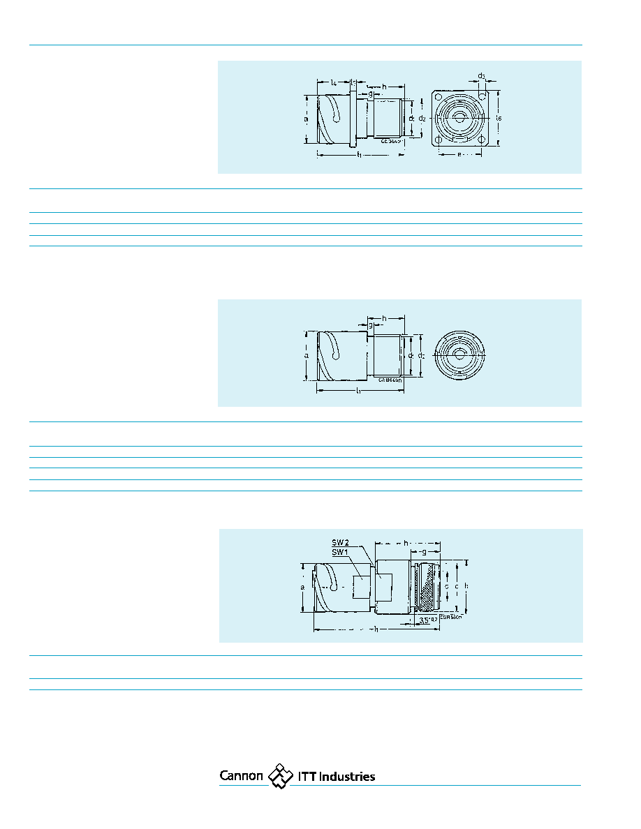
CGE0E...B-03
Wall mounting receptacle,
acc to VG 96929B1,
rear panel mounting,
four threaded holes in flange,
adapter for heat shrink boot,
metric crimp contacts
Shell
a
d
1
d
2
d
3
e
g
h
l
1
l
4
l
5
l
6
size
≠ 0,15
±
0,15
±
0,3
±
0,1
±
0,1
±
0,2
±
0,3
±
0,3
±
0,15
±
0,3
16
27,4
20,0
22,1
M4
24,6
3,2
12,0
41,0
20,0
3,2
32,5
22
37,4
45,8
49,2
M4
31,8
3,2
20,8
55,0
23,15
4,0
41,0
32
53,4
45,8
49,2
M5
44,5
3,5
28,0
66,8
29,0
4,0
57,0
CGE1E...B-03
Cable connecting plug, straigt,
adapter for heat shrink boots,
metric crimp contacts
Shell size
a
d
1
d
2
g
h
l
1
≠ 0,15
±
0,15
±
0,15
±
0,1
±
0,15
±
0,3
18
30,8
25,0
27,0
3,2
20,0
50,0
22
37,4
31,5
34,9
3,2
20,5
54,0
28
53,4
45,8
50,0
3,5
28,0
66,8
32
46,7
41,0
44,4
3,5
25,0
65,8
CGE1E...B-14
Cable connecting plug,
shielded version,
metric crimp contacts
Shell size
a
b
c
d
g
h
l
1
SW1
SW2
±
0,15
±
0,3
±
0,2
max
max
18
37,4
42,0
37,0
25,5
22,5
48,5
95,5
34
38

CGE
7
CGE2E...B-04
CGE2E...B-04-05
Box mounting receptacle,
rear panel mounting,
-04 ≠ four threaded holes in flange,
-04-05 ≠ four through holes in flange
Shell size
a
d
1
d
e
h
l
1
l
2
n
≠ 0,15
±
0,15
Mod 04
Mod 05
±
0,1
±
0,2
±
0,3
±
0,3
±
0,1
16
27,4
22,1
M4
4,3
24,6
20,0
41,0
32,5
3,2
18
30,8
27,0
M4
4,3
27,0
23,15
50,0
35,0
4,0
22
37,4
34,9
M4
4,3
31,8
23,15
54,0
41,0
4,0
28
46,6
42,7
M4
4,3
39,7
-
65,3
50,8
4,0
32
53,4
49,2
M5
5,3
44,5
29,0
66,8
57,0
4,0
CGE6E...B-03
Straight plug
acc to VG 96929A2,
adapter for heat shrink boots,
metric crimp contacts
Shell size
d
1
d
2
d
3
g
h
l
1
max
≠ 0,1
max
±
0,2
max
16
32,0
20,2
22,3
4,3
27,0
44,0
18
36,5
25,8
28,0
4,3
31,8
53,0
22
43,1
31,5
35,0
4,3
39,7
57,0
32
60,1
45,4
49,2
4,3
44,5
65,0
CGE2E...B-16
Box mounting receptacle,
front panel mounting,
four through holes in flange,
threaded bolt termination for
solid copper rail
Shell
a
d
1
d
2
d
e
g
h
l
1
l
2
l
5
l
7
n
SW
size
≠ 0,15
≠ 0,15
+ 0,2
±
0,1
±
0,3
max
±
0,3
±
0,5
+ 0,3
±
0,15
18
30,8
M8
26,9
4,3
27,0
4,0
27,5
55,0
23,15
15,0
35,0
4,0
3
22
37,4
M12
33,2
4,3
31,8
4,4
38,0
65,5
23,15
25,3
41,0
4,0
6
28
46,6
M12
42,8
4,3
39,7
4,0
32,0
61,0
24,15
20,0
50,8
4,0
6
32
53,4
M16
49,2
4,3
44,5
6,0
44,5
73,0
29,0
22,0
57,0
4,0
8

CGE
8
Dimensions are mm (inches)
Subject to changes
CGE6E...B-14
Straight plug
acc to VG 96929F,
360
∞
HF shielding by grounding fingers,
endbells for clamp connection of shielding
braid and for heat shrink boots,
metric crimp contacts
Shell size
c
d
1
d
2
d
4
g
h
l
1
SW
±
0,3
max
±
0,15
±
0,1
±
0,1
±
0,4
max
16
26,0
32,0
24,0
15,5
1,0
25,5
68,0
26
18
32,0
36,5
28,7
20,0
1,0
26,0
73,5
32
22
37,0
43,1
33,7
25,5
1,0
26,0
84,0
38
28
44,0
53,0
40,0
32,0
1,0
26,0
98,0
50
32
31,0
60,1
47,2
38,0
1,0
28,0
95,5
54
CGE8E...B-03
90
∞
plug
with adapter for heat shrink boots,
metric crimp contacts
CGE8E...B-14
90
∞
plug
acc to VG 96929E,
with grounding fingers, adapter for
shielding braid and for use with heat
shrink boots, metric crimp contacts
Shell size
d
1
d
3
l
1
l
3
l
4
l
6
l
SW
max
max
±
1,0
max
max
±
0,2
max
22
43,1
42,0
80,0
41
56
3,2
101,0
38
28
53,0
48,0
78,0
41
56
3,2
102,0
50
32
60,1
52,5
84,0
41
56
3,2
112,0
52
CGE9E...X-B-04
Bulkhead
acc to VG 96929C2,
with through holes in flange
Shell size
a
d
1
e
l
1
l
2
l
3
l
4
≠ 0,15
±
0,1
max
±
0,3
±
0,1
±
0,3
22
46,7
5,3
39,7
51,5
20,6
4,0
50,8

CGE
9
Accessories
Dust cap 121004
for plugs
Order reference
Size
a
b
c
d
+ 0,5
±
10,0
max
max
CA121004-4
16S
4,3
113
29,0
29,9
CA121004-6
18
4,3
127
30,0
33,3
CA121004-8
22
4,3
140
30,0
39,9
CA121004-10
28
4,3
197
30,0
49,2
CA121004-11
32
5,5
197
30,0
55,9
Dust cap 121003
for receptacles
Order reference
Size
a
b
c
d
+ 0,5
±
10,0
max
max
CA121003-4
16S
4,3
100
19,5
32,6
CA12100436
18
4,3
113
25,4
36,7
CA121003-8
22
4,3
127
25,4
43,3
CA121003-10
28
5,5
169
25,4
52,6
CA121004311
32
5,5
169
25,4
59,3
Dummy receptacle
Order ref.
Size
a
b
d
d
1
e
f
g
h
±
0,3
±
0,15
+ 0,2
±
0,2
+0,3 / ≠ 0,1 + 0,1
+ 0,15
248-8504-000
16S
32,5
24,6
3,2
M4
21,5
18,3
29,6
27,4
248-8506-000
18
35,0
27,0
3,2
M4
27,2
23,15
23,8
30,8
248-8508-000
22
41,0
31,8
3,2
M4
27,2
23,15
30,0
37,4
248-8510-000
28
50,8
39,7
3,7
M5
28,2
24,15
38,8
46,7
248-8511-000
32
57,0
44,5
4,4
M5
28,2
24,15
45,2
53,4

CGE
10
Dimensions are mm (inches)
Subject to changes
Accessories
Crimp dies
Contact Order reference
size
upper crimp dies
lower crimp dies
H2
317-8578-006
317-8578-007
H5
317-8578-008
317-8578-009
H9
317-8578-004
317-8578-005
H15
317-8578-002
317-8578-003
H24
317-8578-000
317-8578-001
Sealing gaskets
for rear panel mounting only
Shell
Order references
Order references
size
Polychloroprene
Alu-Flex
(shielded version)
16
075-8504-000
075-8504-001
18
075-8505-000
075-8505-001
22
075-8507-000
075-8507-001
28
075-8509-000
075-8509-001
32
075-8510-000
075-8510-001
O Rings
for sealing of front mounting receptacles
are included in shipment
Shell size
Order reference
16
CGE-SW26
18
CGE-SW26
22
CGE-SW26
28
CGE-SW26
Contacts
Order references for single contacts
Shell size
Spring contact
Cylindrical contact
Contact type
Crimp sleeve
H24
031-8564-000
330-8697-000
Crimp with
031-8567-000
330-8696-000
threaded bolt
031-8658-000
031-8701-002
for 90
∞
plug
252-8583-000
H15
031-8663-000
330-8719-000
with threaded bolt
031-8669-000
031-8701-000
for 90
∞
plug
252-8583-000
031-8701-004
430-8561-009
Crimp version
H9
031-8649-000
330-8698-000
Crimp with
031-8660-000
330-8695-000
threaded bolt
031-8659-000
031-8701-000
for 90
∞
plug
252-8583-000
H5
031-8655-000
330-8710-000
crimp with
031-8656-000
330-8712-000
threaded bolt
H2
031-8616-000
330-8623-000
crimp version
H9
≠
031-8705-000
for bulkhead
Note: When choosing the contacts please make sure that the voltage carrying side of the connection
is quipped with the cylindrical contact.
Crimp Tools
Special Allen Wrenches
for endbell assembly
Description
Designation
Order reference
1
Hand pump
4601.00000.330
121586-0027
2
Foot operation for hand pump
4601.51000.330
121586-0008
3
High pressure hose, length 2 m
4604.00000.020
121586-0023
4
Crimp head
4632.00000.601
121586-0031
5
Safety device incl. bench mounting
CT121086-3079
121086-3079
6
Positioner (to be used with
121086-3079 only)
CT121086-3080
121086-3080
Right hand photograph:
Electro-hydraulic crimp tool HK12EL.
Available upon request ≠ please consult
factory
CGE
11
Product safety Information
THIS NOTE SHOULD BE READ IN CONJUNCTION
WITH THE PRODUCT DATA SHEET/CATALOGUE.
FAILURE TO OBSERVE THE ADVICE IN THIS INFOR-
MATION SHEET AND THE OPERATING CONDITIONS
SPECIFIED IN THE PRODUCT DATA SHEET/
CATALOGUE COULD RESULT IN HAZARDOUS
SITUATIONS.
1. MATERIAL CONTENT AND PHYSICAL
FORM
Electrical connectors do not usually contain
hazardous materials. They contain conducting and
non-conducting materials and can be divided into
two groups.
a) Printed circuit types and low cost audio types
which employ all plastic insulators and casings.
b) Rugged, Fire Barrier and High Reliability types
with metal casings and either natural rubber,
synthetic rubber, plastic or glass insulating
materials.
Contact materials vary with type of connector and
also application and are usually manufactured from
either copper, copper alloys, nickel, alumel, chromel
or steel. In special applications, other alloys may
be specified.
2. FIRE CHARACTERISTICS AND ELECTRIC
SHOCK HAZARD
There is no fire hazard when the connector is
correctly wired and used within the specified
parameters. Incorrect wiring or assembly of the
connector or careless use of metal tools or
conductive fluids, or transit damage to any of the
component parts may cause electric shock or
burns. Live circuits must not be broken by sepa-
rating mated connectors as this may cause arcing,
ionisation and burning.
Heat dissipation is greater at maximum resistance
in a circuit. Hot spots may occur when resistance
is raised locally by damage, e.g. cracked or
deformed contacts, broken strands of wire. Local
overheating may also result from the use of the
incorrect application tools or from poor quality
soldering or slack screw terminals. Overheating may
occur if the ratings in the Product Data Sheet/
Catalogue are exceeded and can cause breakdown
of insulation and hence electric shock.
If heating is allowed to continue it intensifies by
further increasing the local resistance through loss
of temper of spring contacts, formation of oxide
film on contacts and wires, and leakage currents
through carbonisation of insulation and tracking
paths. Fire can then result in the presence of
combustible materials and this may release noxious
fumes. Overheating may not be visually apparent.
Burns may result from touching overheated
components.
ITT Cannon manufactures the highest quality products available in the marketplace; however these products are intended
to be used in accordance with the specifications in this catalog. Any use or application that deviates from stated operating
specifications is not recommended and may be unsafe. No information and data contained in this catalog shall be construed
to create any liability on the part of Cannon. Any new issue of this catalog shall automatically invalidate and supersede
any and all previous issues. A limited warranty applies to Cannon products. Except for obligations assumed by Cannon
under this warranty, Cannon shall not be liable for any loss, damage, cost of repairs, incidental or consequential
damages of any kind, whether or not based on express or implied warranty, contract, negligence or strict liability
arising in connection with the design, manufacture, sale, use or repair of the products. Product availability, prices and
delivery dates are exclusively subject to our respective order confirmation form; the same applies to orders based on
development samples delivered. This catalog is not be construed as an offer. It is intended merely as an invitation to make
an offer. By this publication, Cannon does not assume responsibility or any liability for any patent infringements or other
rights of third parties which may result from its use. Reprinting this catalog is generally permitted, indicating the source.
However, Cannon's prior consent must be obtained in all cases.
Cannon is a trademark of ITT Industries, Inc
3. HANDLING
Care must be taken to avoid damage to any
component parts of electrical connectors during
installation and use. Although there are normally
no sharp edges, care must be taken when handling
certain components to avoid injury to fingers.
Electrical connectors may be damaged in transit to
the customers, and damage may result in creation
of hazards. Products should therefore be examined
prior to installation/use and rejected if found to be
damaged.
4. DISPOSAL
Incineration of certain materials may release
noxious or even toxic fumes.
5. APPLICATION
Connectors with exposed contacts should not be
selected for use on the current supply side of an
electrical circuit, because an electric shock could
result from touching exposed contacts on an
unmated connector. Voltages in excess of 30 V ac
or 42.5 V dc are potentially hazardous and care
should be taken to ensure that such voltages can
not be transmitted in any way to exposed metal parts
of the connector body. The connector and wiring
should be checked, before making live, to have no
damage to metal parts or insulators, no solder blobs,
loose strands, conducting lubricants, swarf, or any
other undesired conducting particles. Insulation
resistance should be checked to make certain that
no low resistance joints or spurious conducting path
are existing between contacts and exposed metal
parts of the connector body. Further the contact
resistance of the connectors should be measured
within the electrical circuit in order to identify high
resistances which result in excessive connector
heating.
Always use the correct application tools as specified
in the Data Sheet/Catalogue.
Do not permit untrained personnel to wire, assemble
or tramper with connectors.
For operation voltage please see appropriate national
regulations.
IMPORTANT GENERAL INFORMATION.
1. Air and creepage paths/Operating voltage
The admissible operating voltages depend on the
individual applications and the valid national and
other applicable safety regulations.
For this reason the air and creepage path data
are only reference values. Observe reduction of air
and creepage paths due to PC board and/or harness-
ing.
2. Temperature
All information given are temperature limits. The
operation temperature depends on the individual
application.
3. Other important information
Cannon continuously endeavours to improve their
products. Therefore, Cannon products may deviate
from the description, technical data and shape as
shown in this catalogue and data sheets.
4. Harnessing and Assembly Instructions
If applicable, our special harnessing and/or assem-
bly instruction has to be adhered to. This is provid-
ed at request.