
Navigation
C
Dimensions are shown: mm (inch)
Dimensions subject to change
www.ittcannon.com
1
NSE10 Series
Navigation Switch Encoders
NOTE: Specifications listed above are for switches with standard options.
For information on specific and custom switches, consult Customer Service Center.
Features/Benefits
∑
Reduced size 10 mm
∑
Hollow shaft
∑
Self clinching terminals
∑
Positive detent feeling
Typical Applications
∑
Audio / Video equipment
∑
Navigation systems
∑
Computer peripherals
Electrical
MAXIMUM VOLTAGE: 5 VDC.
CURRENT DC: 1 mA
DIELECTRIC STRENGTH: 50 VAC.
INSULATION RESISTANCE: 50 M
min / 50 VDC.
BOUNCE TIME:
5 ms
Environmental
OPERATING TEMPERATURE: -5∞C to +45∞C.
STORAGE TEMPERATURE: -15∞C to +65∞C.
Process
SOLDERING PROCESS:
Manual soldering 300∞C max., 3s max.
Wave soldering 260∞C max., 3s max.
No cleaning.
Mechanical
NUMBER OF DETENT: 24
DETENT TORQUE: 5 ± 3 mN.m
ROTATIONAL ANGLE: 360∞ endless.
ROTATIONAL LIFE: 100,000 cycles (1 cycle: 360∞ CW + 360∞ CCW).
Construction
FUNCTION: Incremental signal.
CONTACT ARRANGEMENT: Phase difference output of two signal
A and B.
TERMINAL: PC pin.
Number
Number
Detent
Mounting
of Pulse
of Detent
Torque
Height
Designation
12
24
5mN.m
7
NSE10DH127
12
24
5mN.m
9
NSE10DH129
12
24
5mN.m
11
NSE10DH1211
How To Order
Our easy build-a-switch concept allows you to mix and match options to create the switch you need. To order, select desired
option from each category and place it in the appropriate box.
Detent
D
With detent
Appearance Type
H
Horizontal axis
N
S
E
D
2
H
1
Pulse Number
12
12
Axis Height
7
7 mm
9
9 mm
11
11 mm
1
0
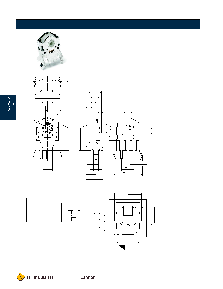
30∞
±
3∞
( x 6)
60∞
±
3∞
0,6
1,7
+0,05
0
¯ 2,98
±
0,1
4
2
3,5
4
6,8
4,2
2
9,7
(x3)
0,8
±
0,1
5
H
5,3
0,7
4
5
4,1
1,25
3,05
4
11,6
±
1
(
¯
3,8 )
2,8
10,8
9,7
±
1
3,6
±
0,5
1,8
+0,1
0
9,7
±
1
5
t = 0,4
2
2,1
+0,1
0
2,4
±
0,5
1,3
±
1
4,2
±
0,5
6,8
±
0,5
0,8
±
0,5
¯
( x 3 )
1
+0,1
0
ELECTRICAL GRAPH
Shaft rotational direction
Signal
Output
C.W.
A (Terminal A-C)
ON
OFF
B (Terminal B-C)
ON
OFF
Axis side
COM B A
Shaft hole orientation
may vary
A B COM
Leg position
LAYOUT
P.C.B. THICKNESS T = 1,6
View from mounting side
Dimensions are shown: mm (inch)
Dimensions subject to change
www.ittcannon.com
2
Navigation
C
NSE10
NSE10 Series
Navigation Switch Encoders
OPTION
CODE
AXIS HEIGHT
7
7 mm
9
9 mm
11
11 mm

Bushing Dimension
7
Length = 7 mm
Fixed Pillar
N
without locating pin
Dimensions are shown: mm (inch)
Dimensions subject to change
www.ittcannon.com
3
Navigation
C
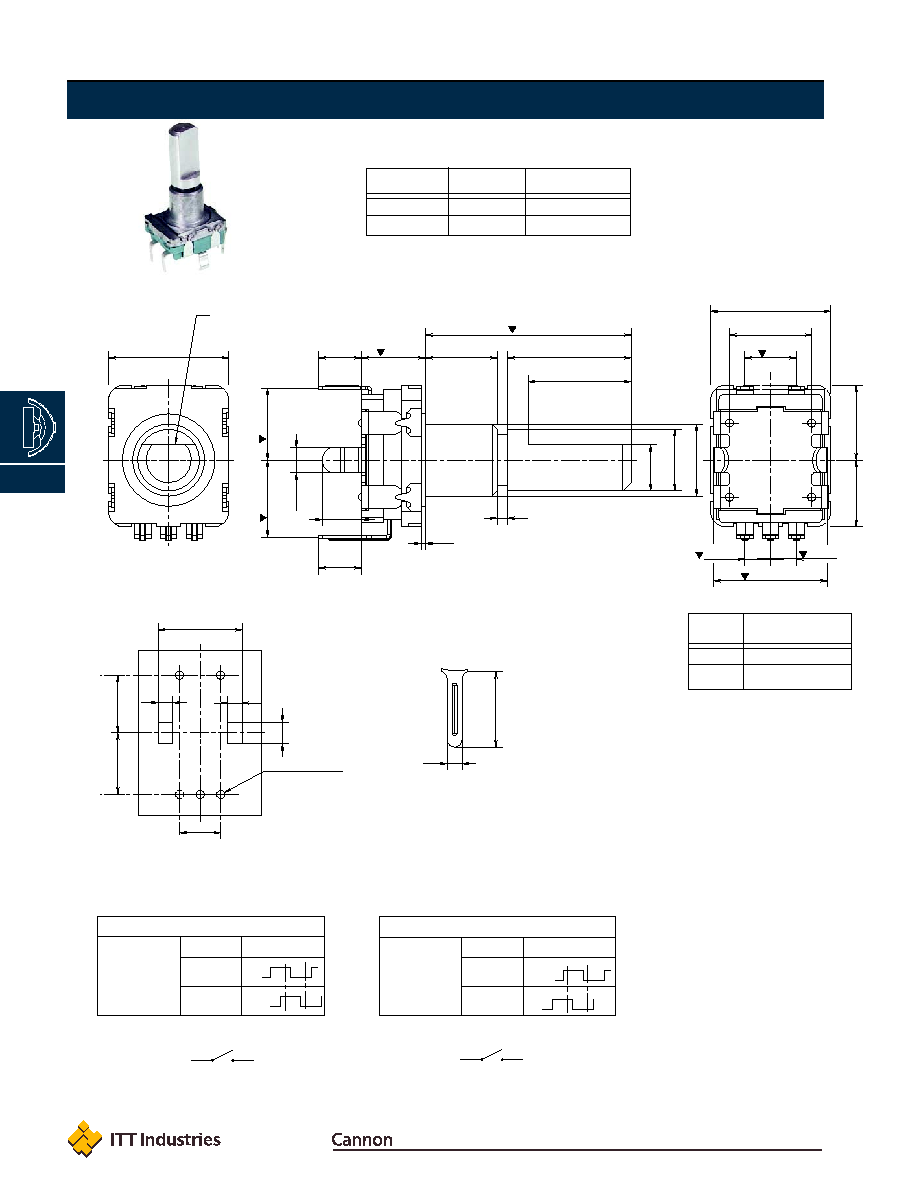
NSE11 Series
Navigation Switch Encoders
NOTE: Specifications listed above are for switches with standard options.
For information on specific and custom switches, consult Customer Service Center.
Features/Benefits
∑
Select switch
∑
Metallic shaft
∑
Self clinching terminals
∑
Positive detent feeling
∑
Large variety of shaft
Typical Applications
∑
Audio / Video equipment
∑
Navigation systems
∑
Computer peripherals
∑
Car radio
Electrical
MAXIMUM VOLTAGE: 5 VDC.
MAXIMUM CURRENT DC: 10 mA
MINIMUM CURRENT DC: 1 mA
DIELECTRIC STRENGTH: 300 VAC / 1 mA.
INSULATION RESISTANCE: 100 M
min.
BOUNCE TIME:
2 ms
Switch Function
CONTACT: SPST
MAXIMUM POWER: 5 VDC 10 mA (min. 1 mA)
CONTACT RESISTANCE: Initial 100m
TRAVEL: 0,5 mm +/- 0,4 mm
OPERATING FORCE: 4,5 +/- 1,5 N
LIFE TIME: 20,000 operations
Environmental
OPERATING TEMPERATURE: -30∞C to +70∞C.
STORAGE TEMPERATURE: -40∞C to +85∞C.
Process
SOLDERING PROCESS:
Manual soldering 300∞C max., 3s max.
Wave soldering 260∞C max., 3s max.
No cleaning.
Mechanical
NUMBER OF DETENT: 20 or 30
DETENT TORQUE: 3 - 20 mN.m
ROTATIONAL ANGLE: 360∞ endless.
ROTATIONAL LIFE: 15,000 cycles (1 cycle: 360∞ CW + 360∞ CCW).
Construction
FUNCTION: Incremental signal + select switch.
CONTACT ARRANGEMENT: Phase difference output of two signal
A and B.
TERMINAL: PC pin.
Number
Number
Bracket
Select
of Pulse of Detent
Spacing
Function
Designation
15
30
11 mm
No
NSE11DV57NCF215A
20
20
11 mm
No
NSE11DV57NCF220A
15
30
11 mm
Yes
NSE11DSV57NAF215A
20
20
11 mm
Yes
NSE11DSV57NAF220A
15
30
13,8 mm
Yes
NSE11DSV57NAF215F
20
20
13,8 mm
Yes
NSE11DSV57NAF220F
How To Order
Our easy build-a-switch concept allows you to mix and match options to create the switch you need. To order, select desired
option from each category and place it in the appropriate box.
N
S
E
D
S
V
1
1
Detent
D
With detent
Switching Function
(NONE)
No Switch
S
Switch
Appearance Type
V
Vertical axis
Pulse
15
15 pulse
20
20 pulse
5
7
N
F
2
Terminal Length
5
4,2 mm
Shaft Type
F
with a flat
Shaft Length & Push Switch Slot
A
With select; Length of Shaft = 12,5 mm; push switch slot 0,5 mm
C
Without select; Length of Shaft = 13 mm; no push switch slot
Flat Length
2
10 mm
Bracket Spacing
A
11 mm
F
13,8 mm
NSE11
Dimensions are shown: mm (inch)
Dimensions subject to change
www.ittcannon.com
4
Navigation
C
NSE11 Series
Navigation Switch Encoders
11,7
6,2
7,3
6,5
11,7
8
F
2,45
±
0,1
4,5
¯
6 0 -0,05
10
LS
7
4,2
±
0,3
7
±
0,5
7,5
±
0,5
3,8
±
0,3
5
5,3
0,9
4,2
±
0,3
20
0,4
A
¯
7
2,5
±
0,15
2,5
±
0,15
2,6
+0,1 0
10,2
±
0,1
1,8 +0,1
0
1,8 +0,1
0
¯ x 5 HOLES
1+0,1
0
7
7,5
5
ELECTRICAL GRAPH
Shaft rotational direction
Signal
Output
C.W.
A (Terminal A-C)
ON
OFF
B (Terminal B-C)
ON
OFF
TERMINAL DETAIL
Push switch stroke 0,5
±
0,4
D
E
SWITCH GRAPH
A C B
E D
A C B
E D
LAYOUT
P.C.B. THICKNESS T = 1,6
View from mounting side
P.C.B. THICKNESS T = 1,6
View from mounting side
ELECTRICAL GRAPH
Shaft rotational direction
Signal
Output
C.W.
A (Terminal A-C)
ON
OFF
B (Terminal B-C)
ON
OFF
D
E
SWITCH GRAPH
Shaft flat orientation
may vary
15 Pulse
20 Pulse
OPTION
LS
A
CODE
Length of Shaft
Push Switch Slot
A
- with select
12,5 mm
0,5
C
- without select
13 mm
no push switch slot
OPTION
F
CODE
Bracket Spacing
A
11 mm
F
13,8 mm
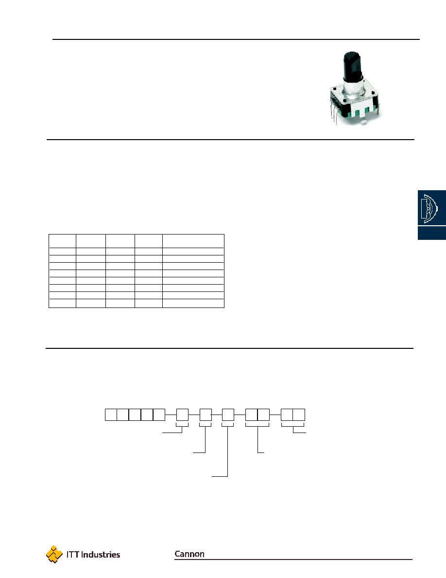
NSE12 Series
Navigation Switch Encoders
NOTE: Specifications listed above are for switches with standard options.
For information on specific and custom switches, consult Customer Service Center.
Features/Benefits
∑
Select switch
∑
Low profile
∑
Self clinching terminals
∑
Positive detent feeling
Typical Applications
∑
Audio / Video equipment
∑
Navigation systems
∑
White goods equipment
∑
Car radio
Electrical
MAXIMUM VOLTAGE: 5 VDC.
MAXIMUM CURRENT DC: 10 mA
MINIMUM CURRENT DC: 1 mA
DIELECTRIC STRENGTH: 50 VAC / 1 mA.
INSULATION RESISTANCE: 10 M
.
BOUNCE TIME:
2 ms
Switch Function
CONTACT: SPST
MAXIMUM POWER: 5 VDC - 10 mA (min. 1 mA).
CONTACT RESISTANCE INITIAL: 100 m
.
TRAVEL: 0,5 mm +0,2/-0,1 mm
OPERATING FORCE: 4,5 ± 1,5 N.
LIFE TIME: 20,000 operations.
Environmental
OPERATING TEMPERATURE: -10∞C to +70∞C.
STORAGE TEMPERATURE: -40∞C to +85∞C.
Process
SOLDERING PROCESS:
Manual soldering 300∞C max., 3s max.
Wave soldering 260∞C max., 3s max.
No cleaning.
Mechanical
NUMBER OF DETENT: 12 or 24
DETENT TORQUE: 3 - 20 mN.m
ROTATIONAL ANGLE: 360∞ endless.
ROTATIONAL LIFE: 30,000 cycles (1 cycle: 360∞ CW + 360∞ CCW).
Construction
FUNCTION: Incremental signal + select switch.
CONTACT ARRANGEMENT: Phase difference output of two signal
A and B.
TERMINAL: PC pin.
Number
Number
Select
of Pulse of Detent
Height
Function
Designation
12
12
20 mm
No
NSE12DV1220
24
24
20 mm
No
NSE12DV2420
12
12
25 mm
No
NSE12DV1225
24
24
25 mm
No
NSE12DV2425
12
12
20 mm
Yes
NSE12DSV1220
24
24
20 mm
Yes
NSE12DSV2420
12
12
25 mm
Yes
NSE12DSV1225
24
24
25 mm
Yes
NSE12DSV2425
How To Order
Our easy build-a-switch concept allows you to mix and match options to create the switch you need. To order, select desired
option from each category and place it in the appropriate box.
Detent
D
With detent
Switch Function
(NONE)
No switch
S
Switch
N
S
E
D
Pulse Number
12
12
24
24
Total Height
20
20 mm
25
25 mm
1
2
Appearance Type
V
Vertical axis
V
Dimensions are shown: mm (inch)
Dimensions subject to change
www.ittcannon.com
5
Navigation
C