© 2000 IXYS All rights reserved
1 - 2
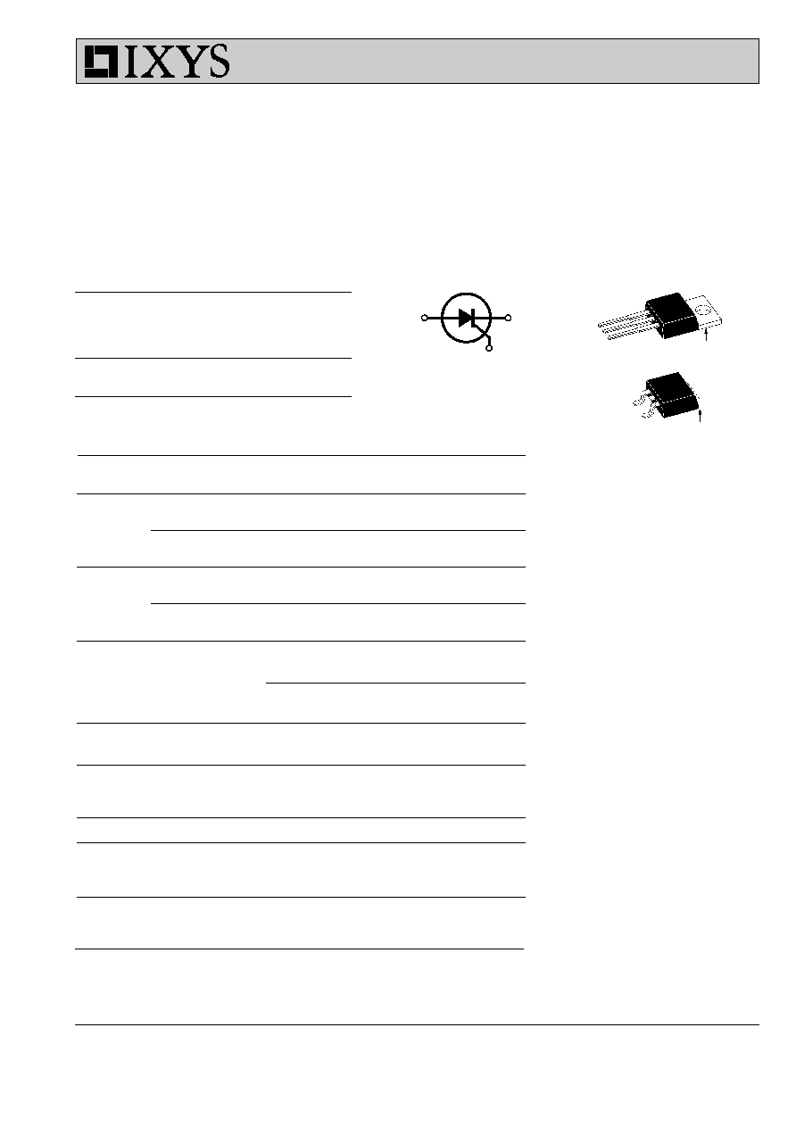
Phase Control Thyristors
V
RRM
= 800-1200 V
I
T(RMS)
= 29 A
I
T(AV)M
= 19 A
V
RSM
V
RRM
Type
Type
V
DSM
V
DRM
V
V
TO 220
TO 263
800
800
CS 19-08ho1
CS 19-08ho1S
1200
1200
CS 19-12ho1
CS 19-12ho1S
Symbol
Test Conditions
Maximum Ratings
I
T(RMS)
T
VJ
= T
VJM
29
A
I
T(AV)M
T
C
= 85
∞
C; 180
∞
sine
19
A
I
TSM
T
VJ
= 45
∞
C;
t = 10 ms (50 Hz), sine
160
A
V
R
= 0 V
t = 8.3 ms (60 Hz), sine
180
A
T
VJ
= T
VJM
t = 10 ms (50 Hz), sine
140
A
V
R
= 0 V
t = 8.3 ms (60 Hz), sine
160
A
I
2
t
T
VJ
= 45
∞
C
t = 10 ms (50 Hz), sine
128
A
2
s
V
R
= 0 V
t = 8.3 ms (60 Hz), sine
134
A
2
s
T
VJ
= T
VJM
t = 10 ms (50 Hz), sine
100
A
2
s
V
R
= 0 V
t = 8.3 ms (60 Hz), sine
105
A
2
s
(di/dt)
cr
T
VJ
= T
VJM
repetitive, I
T
= 20 A
100
A/
µ
s
f = 50
Hz, t
P
=200
µ
s
V
D
= 2/3 V
DRM
I
G
= 0.15 A
non repetitive, I
T
= I
T(AV)M
500
A/
µ
s
di
G
/dt = 0.15 A/
µ
s
(dv/dt)
cr
T
VJ
= T
VJM
;
V
DR
= 2/3 V
DRM
500
V/
µ
s
R
GK
=
; method 1 (linear voltage rise)
P
GM
T
VJ
= T
VJM
t
P
=
30
µ
s
5
W
I
T
= I
T(AV)M
t
P
= 300
µ
s
2,5
W
P
GAV
0.5
W
V
RGM
10
V
T
VJ
-40...+125
∞
C
T
VJM
125
∞
C
T
stg
-40...+125
∞
C
M
d
Mounting torque with screw M3; TO220
0.45/4
Nm/lb.in.
Mounting torque with screw M3.5; TO220
0.55/5
Nm/in.
Weight
2
g
Features
q
SCR for frequency up to 400Hz
q
International standard package
q
High performance glass
passivated chip
q
Long-term stability of leakage
current and blocking voltage
q
Epoxy meets UL 94V-0
Applications
q
Motor control
q
Power converter
q
AC power controller
q
Light and temperature control
q
SCR for inrush current limiting
in power supplies or AC drive
Advantages
q
Space and weight savings
q
Simple mounting
Data according to IEC 60747
IXYS reserves the right to change limits, test conditions and dimensions
CS 19
A
C
G
C
G
TO-263 AA
A (TAB)
TO-220 AB
A (TAB)
C
A
G
A
=
Anode,
C
=
Cathode,
G = Gate
046

© 2000 IXYS All rights reserved
2 - 2
CS 19
Symbol
Test Conditions
Characteristic Values
I
R
, I
D
T
VJ
= T
VJM
; V
R
= V
RRM
; V
D
= V
DRM
5
mA
V
T
I
T
= 20 A; T
VJ
= 25
∞
C
1.6
V
V
T0
For power-loss calculations only (T
VJ
= 125
∞
C)
0.85
V
r
T
27
m
V
GT
V
D
= 6 V;
T
VJ
= 25
∞
C
1.5
V
T
VJ
= -40
∞
C
2.5
V
I
GT
V
D
= 6 V;
T
VJ
= 25
∞
C
28
mA
T
VJ
= -40
∞
C
50
mA
V
GD
T
VJ
= T
VJM
;
V
D
= 2/3 V
DRM
0.2
V
I
GD
3
mA
I
L
T
VJ
= 25
∞
C; t
P
= 10
µ
s
75
mA
I
G
= 0.1 A; di
G
/dt = 0.1 A/
µ
s
I
H
T
VJ
= 25
∞
C; V
D
= 6 V; R
GK
=
50
mA
t
gd
T
VJ
= 25
∞
C; V
D
= 1/2 V
DRM
2
µ
s
I
G
= 0.1 A; di
G
/dt = 0.1 A/
µ
s
R
thJC
DC current
1.0
K/W
R
thCK
DC current
typ 0.25
K/W
a
Max. acceleration, 50 Hz
50
m/s
2
Dimensions in mm (1 mm = 0.0394")
Dim.
Millimeter
Inches
Min.
Max.
Min.
Max.
A
4.06
4.83
.160
.190
A1
2.03
2.79
.080
.110
b
0.51
0.99
.020
.039
b2
1.14
1.40
.045
.055
c
0.46
0.74
.018
.029
c2
1.14
1.40
.045
.055
D
8.64
9.65
.340
.380
D1
7.11
8.13
.280
.320
E
9.65
10.29
.380
.405
E1
6.86
8.13
.270
.320
e
2.54
BSC
.100
BSC
L
14.61
15.88
.575
.625
L1
2.29
2.79
.090
.110
L2
1.02
1.40
.040
.055
L3
1.27
1.78
.050
.070
L4
0
0.38
0
.015
R
0.46
0.74
.018
.029
Dim.
Millimeter
Inches
Min.
Max.
Min.
Max.
A
12.70
13.97
0.500
0.550
B
14.73
16.00
0.580
0.630
C
9.91
10.66
0.390
0.420
D
3.54
4.08
0.139
0.161
E
5.85
6.85
0.230
0.270
F
2.54
3.18
0.100
0.125
G
1.15
1.65
0.045
0.065
H
2.79
5.84
0.110
0.230
J
0.64
1.01
0.025
0.040
K
2.54
BSC
0.100
BSC
M
4.32
4.82
0.170
0.190
N
1.14
1.39
0.045
0.055
Q
0.35
0.56
0.014
0.022
R
2.29
2.79
0.090
0.110
TO 263 AA
TO 220 AB
046