© 1999 IXYS All rights reserved
1 - 2
Features
q
International standard package
q
Planar passivated chips
q
Very short recovery time
q
Extremely low switching losses
q
Low I
RM
-values
q
Soft recovery behaviour
q
Epoxy meets UL 94V-0
Applications
q
Antiparallel diode for high frequency
switching devices
q
Antisaturation diode
q
Snubber diode
q
Free wheeling diode in converters
and motor control circuits
q
Rectifiers in switch mode power
supplies (SMPS)
q
Inductive heating
q
Uninterruptible power supplies (UPS)
q
Ultrasonic cleaners and welders
Advantages
q
Avalanche voltage rated for reliable
operation
q
Soft reverse recovery for low
EMI/RFI
q
Low I
RM
reduces:
- Power dissipation within the diode
- Turn-on loss in the commutating
switch
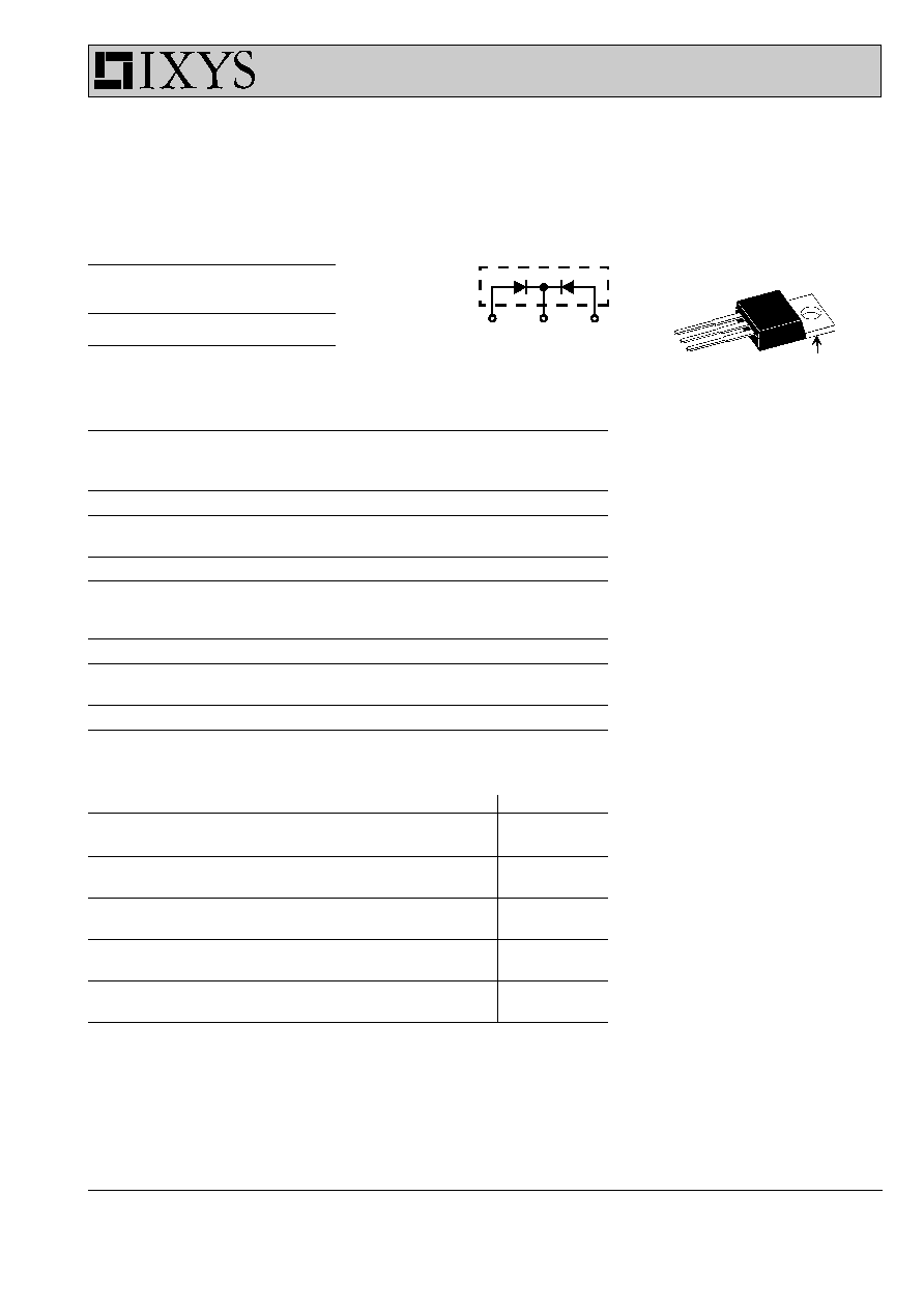
Dimensions see IXYS Catalog 2000 (CD)
TO-220 AB
C
A
A
A C A
A = Anode, C = Cathode, TAB = Cathode
C (TAB)
Pulse test:
x
Pulse Width = 5 ms, Duty Cycle < 2.0 %
y
Pulse Width = 300
µ
s, Duty Cycle < 2.0 %
Data according to IEC 60747 and per diode unless otherwise specified
IXYS reserves the right to change limits, test conditions and dimensions.
HiPerFRED
TM
Epitaxial Diode
with common cathode and soft recovery
DSEC 16-12A
I
FAV
= 2x 10 A
V
RRM
= 1200 V
t
rr
= 40 ns
V
RSM
V
RRM
Type
V
V
1200
1200
DSEC 16-12A
Symbol
Test Conditions
Maximum Ratings
I
FRMS
14
A
I
FAVM
T
C
= 115∞C; rectangular, d = 0.5
10
A
I
FRM
t
P
< 10
µ
s; rep. rating, pulse width limited by T
VJM
tbd
A
I
FSM
T
VJ
= 45∞C; t
p
= 10 ms (50 Hz), sine
40
A
E
AS
T
VJ
= 25∞C; non-repetitive
6.9
mJ
I
AS
= 8 A; L = 180 µH
I
AR
V
A
= 1.25∑V
R
typ.; f = 10 kHz; repetitive
0.8
A
T
VJ
-55...+175
∞C
T
VJM
175
∞C
T
stg
-55...+150
∞C
P
tot
T
C
= 25∞C
60
W
M
d
mounting torque
0.45...0.55
Nm
4...5
lb.in.
Weight
typical
2
g
Symbol
Test Conditions
Characteristic Values
typ.
max.
I
R
x
T
VJ
= 25∞C
V
R
= V
RRM
60
µ
A
T
VJ
= 150∞C V
R
= V
RRM
0.25
mA
V
F
y
I
F
= 10 A;
T
VJ
= 150∞C
1.96
V
T
VJ
= 25∞C
2.94
V
R
thJC
2.5
K/W
R
thCH
0.5
K/W
t
rr
I
F
= 1 A; -di/dt = 50 A/
µ
s;
40
ns
V
R
= 30 V; T
VJ
= 25∞C
I
RM
V
R
= 100 V; I
F
= 12 A; -di
F
/dt = 100 A/
µ
s
8.5
A
T
VJ
= 100∞C
937
© 1999 IXYS All rights reserved
2 - 2
DSEC 16-12A
200
600
1000
0
400
800
90
100
110
120
130
140
150
0.00001
0.0001
0.001
0.01
0.1
1
0.001
0.01
0.1
1
10
0
40
80
120
160
0.0
0.5
1.0
1.5
2.0
K
f
T
VJ
∞C
-di
F
/dt
t
s
K/W
0
200
400
600
800
1000
0
40
80
120
0.0
0.4
0.8
1.2
V
FR
di
F
/dt
V
200
600
1000
0
400
800
0
10
20
30
40
100
1000
0
500
1000
1500
2000
0
1
2
3
4
0
5
10
15
20
25
30
I
RM
Q
r
I
F
A
V
F
-di
F
/dt
-di
F
/dt
A/
µ
s
A
V
nC
A/
µ
s
A/
µ
s
t
rr
ns
t
fr
Z
thJC
A/
µ
s
µ
s
DSEP 8-12A / DSEC 16-12A
I
F
= 20A
I
F
= 10A
I
F
= 5A
T
VJ
= 100∞C
V
R
= 600V
T
VJ
= 100∞C
I
F
= 10A
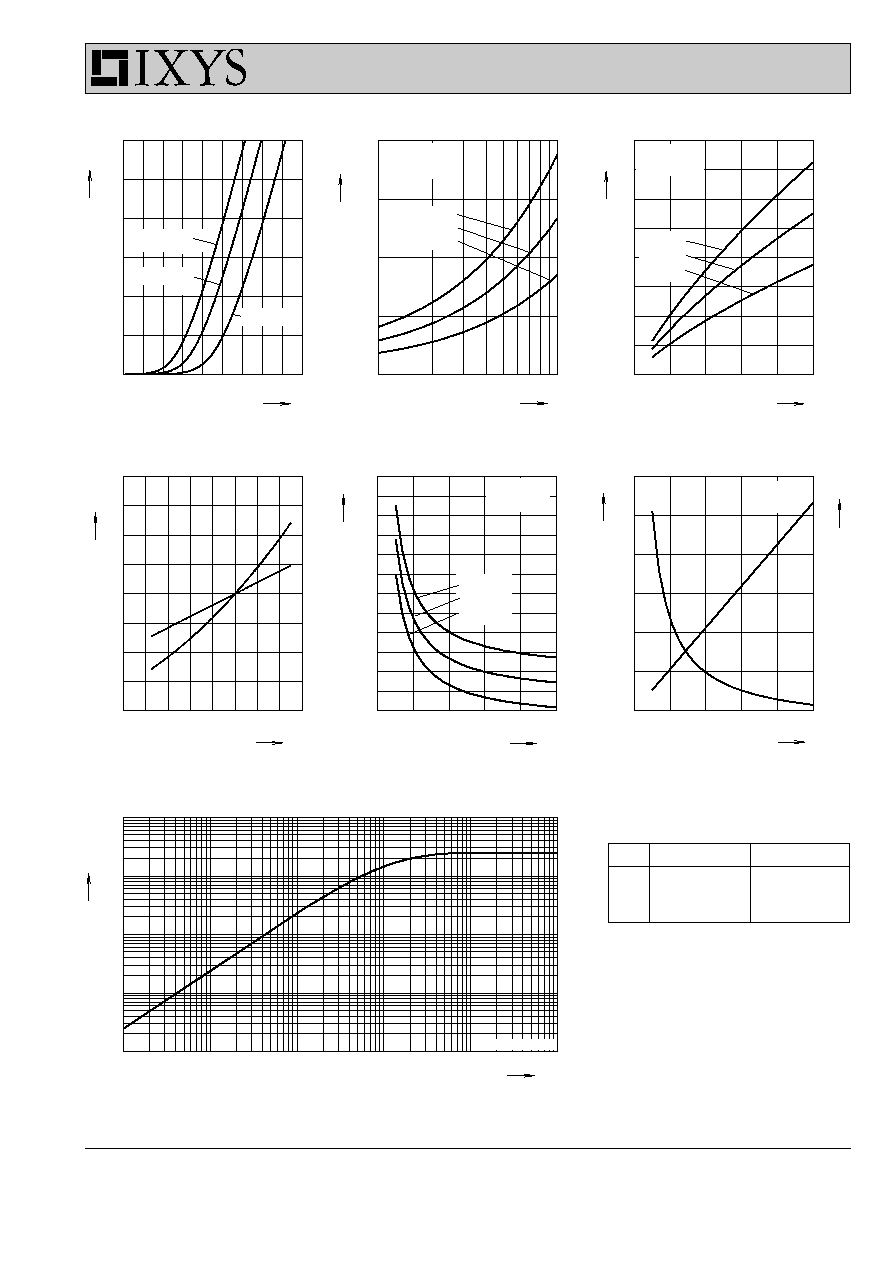
Fig. 3 Peak reverse current I
RM
versus -di
F
/dt
Fig. 2 Reverse recovery charge Q
r
versus -di
F
/dt
Fig. 1 Forward current I
F
versus V
F
T
VJ
= 100∞C
V
R
= 600V
T
VJ
= 100∞C
V
R
= 600V
I
F
= 20A
I
F
= 10A
I
F
= 5A
Q
r
I
RM
Fig. 4 Dynamic parameters Q
r
, I
RM
versus T
VJ
Fig. 5 Recovery time t
rr
versus -di
F
/dt
Fig. 6 Peak forward voltage V
FR
and t
fr
versus di
F
/dt
I
F
= 20A
I
F
= 10A
I
F
= 5A
t
fr
V
FR
Fig. 7 Transient thermal resistance junction to case
Constants for Z
thJC
calculation:
i
R
thi
(K/W)
t
i
(s)
1
1.449
0.0052
2
0.558
0.0003
3
0.493
0.017
T
VJ
= 25∞C
T
VJ
=100∞C
T
VJ
=150∞C