© 2002 IXYS All rights reserved
1 - 2
202
IXYS reserves the right to change limits, test conditions and dimensions.
V
RRM
= 600 V
I
D(AV)M
= 6.6 A
C
junction
= 9 pF
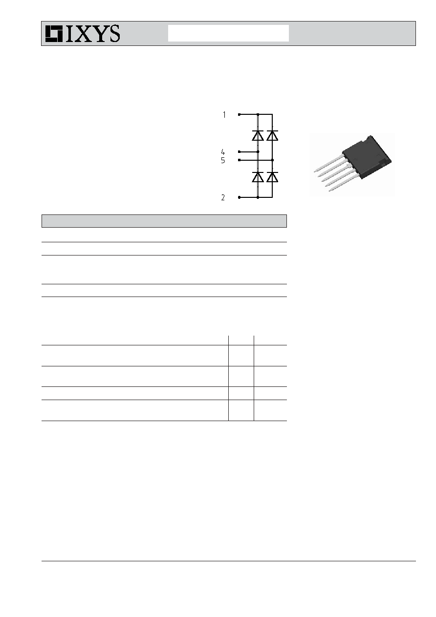
Silicon Carbide
Schottky
Rectifier Bridge
in ISOPLUS i4-PAC
TM
1
5
Advanced Technical Information
FBS 10-06SC
Features
∑ Silicon Carbide Schottky Diodes
- no reverse recovery at turn off - only
charge of junction capacity - soft turn
off waveform
- no forward recovery at turn on
- switching behaviour independent of
temperature
- low leakage current
∑ ISOPLUS i4-PAC(TM) package
- isolated back surface
- low coupling capacity between pins
and heatsink
- enlarged creepage towards heatsink
- application friendly pinout
- high reliability
- industry standard outline
Applications
∑ output rectifiers of high end switched
mode power supplies
∑ other high frequency rectifiers
Rectifier Bridge
Symbol
Conditions
Maximum Ratings
V
RRM
600
V
I
FAV
T
C
= 90∞C; sine 180∞ (per diode)
3
A
I
D(AV)M
T
C
= 90∞C
6.6
A
I
FSM
T
VJ
= 25∞C; t = 10 ms; sine 50 Hz
12
A
P
tot
T
C
= 25∞C
(per diode)
19
W
Symbol
Conditions
Characteristic Values
(T
VJ
= 25
∞
C, unless otherwise specified)
min.
typ.
max.
V
F
I
F
= 4 A;
T
VJ
= 25∞C
1.7
2.0
V
T
VJ
= 125∞C
1.9
V
I
R
V
R
= V
RRM
;
T
VJ
= 25∞C
0.2
mA
T
VJ
= 125∞C
0.04
mA
C
J
V
R
= 400 V;
T
VJ
= 125∞C
9
pF
R
thJC
(per diode)
8 K/W
R
thJS
11.5
K/W
Data according to IEC 60747 and refer to a single diode unless otherwise stated.
© 2002 IXYS All rights reserved
2 - 2
FBS 10-06SC
Component
Symbol
Conditions
Maximum Ratings
T
VJ
-55...+175
∞
C
T
stg
-55...+125
∞
C
V
ISOL
I
ISOL
1 mA; 50/60 Hz
2500
V~
F
C
mounting force with clip
20...120
N
Symbol
Conditions
Characteristic Values
min.
typ.
max.
C
p
coupling capacity between shorted
40
pF
pins and mounting tab in the case
d
S
,d
A
pin - pin
1.7
mm
d
S
,d
A
pin - backside metal
5.5
mm
Weight
9
g
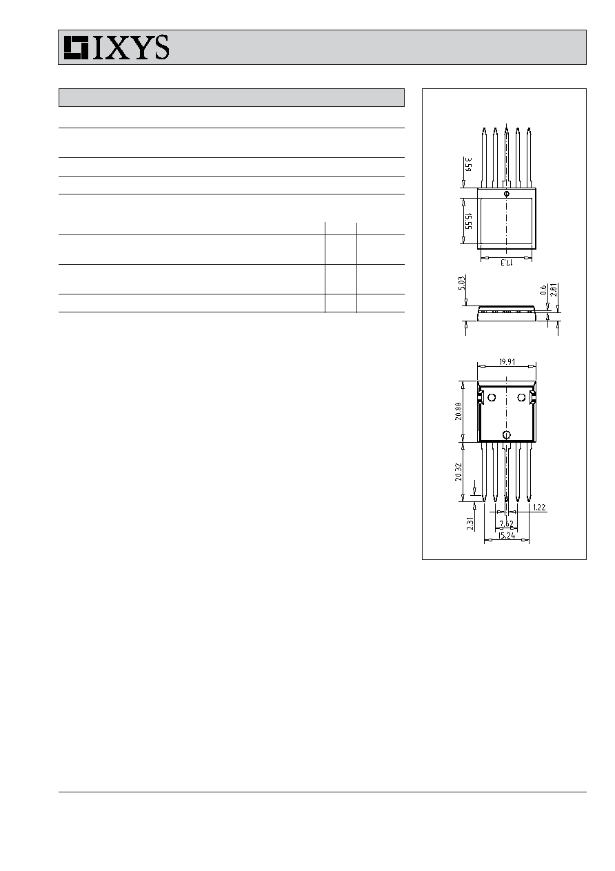
Dimensions in mm (1 mm = 0.0394")