
1 - 2
© 2001 IXYS All rights reserved
145
Features
∑ IGBT
- low saturation voltage
- positive temperature coefficient for
easy paralleling
- fast switching
- short tail current for optimized
performance in resonant circuits
∑ HiPerFRED
TM
diodes
- fast reverse recovery
- low operating forward voltage
- low leakage current
∑ ISOPLUS i4-PAC
TM
package
- isolated back surface
- low coupling capacity between pins
and heatsink
- enlarged creepage towards heatsink
- application friendly pinout
- low inductive current path
- high reliability
- industry standard outline
Applications
switches to control bidirectional current
flow by a single control signal:
∑ matrix converters
∑ spare matrix converters
∑ AC controllers
IGBT
Symbol
Conditions
Maximum Ratings
V
CES
T
VJ
= 25∞C to 150∞C
1200
V
V
GES
±
20
V
I
C25
T
C
= 25∞C
50
A
I
C90
T
C
= 90∞C
32
A
I
CM
V
GE
=
±
15 V; R
G
= 39
; T
VJ
= 125∞C
50
A
V
CEK
RBSOA, Clamped inductive load; L = 100 µH
V
CES
t
SC
V
CE
= 900V; V
GE
=
±
15 V; R
G
= 39
; T
VJ
= 125∞C
10
µs
(SCSOA)
non-repetitive
P
tot
T
C
= 25∞C
200
W
Symbol
Conditions
Characteristic Values
(T
VJ
= 25
∞
C, unless otherwise specified)
min.
typ.
max.
V
CE(sat)
I
C
= 30 A; V
GE
= 15 V; T
VJ
= 25∞C
2.0
2.6
V
T
VJ
= 125∞C
2.3
V
V
GE(th)
I
C
= 1 mA; V
GE
= V
CE
4.5
6.5
V
I
CES
V
CE
= V
CES
;
V
GE
= 0 V; T
VJ
= 25∞C
0.4
mA
T
VJ
= 125∞C
0.4
mA
I
GES
V
CE
= 0 V; V
GE
=
±
20 V
200
nA
t
d(on)
150
ns
t
r
60
ns
t
d(off)
700
ns
t
f
50
ns
E
on
3.6
mJ
E
off
3.0
mJ
C
ies
V
CE
= 25 V; V
GE
= 0 V; f = 1 MHz
2
nF
Q
Gon
V
CE
= 600 V; V
GE
= 15 V; I
C
= 30 A
250
nC
R
thJC
0.6 K/W
R
thJS
1.2
K/W
Inductive load, T
VJ
= 125∞C
V
CE
= 600 V; I
C
= 30 A
V
GE
= ±15 V; R
G
= 39
I
C25
= 50 A
V
CES
= 1200 V
V
CE(sat) typ.
= 2.0 V
Bidirectional Switch
with IGBT
and fast Diode Bridge
in ISOPLUS i4-PAC
TM
1
5
Advanced Technical Information
IXYS Semiconductor GmbH
Edisonstr. 15,
D-68623 Lampertheim
Phone: +49-6206-503-0, Fax: +49-6206-503627
IXYS Corporation
3540 Bassett Street, Santa Clara CA 95054
Phone: (408) 982-0700, Fax: 408-496-0670
FIO 50-12BD
2 - 2
© 2001 IXYS All rights reserved
FIO 50-12BD
Component
Symbol
Conditions
Maximum Ratings
T
VJ
-55...+150
∞
C
T
stg
-55...+125
∞
C
V
ISOL
I
ISOL
1 mA; 50/60 Hz
2500
V~
F
C
mounting force with clip
20...120
N
Symbol
Conditions
Characteristic Values
min.
typ.
max.
C
p
coupling capacity between shorted
40
pF
pins and mounting tab in the case
d
S
,d
A
pin - pin
1.7
mm
d
S
,d
A
pin - backside metal
5.5
mm
Weight
9
g
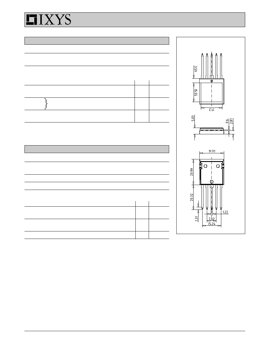
Dimensions in mm (1 mm = 0.0394")
Diodes
Symbol
Conditions
Maximum Ratings
I
F25
T
C
= 25∞C
48
A
I
F90
T
C
= 90∞C
25
A
Symbol
Conditions
Characteristic Values
min.
typ.
max.
V
F
I
F
= 30 A; T
VJ
= 25∞C
2.4
2.8
V
T
VJ
= 125∞C
1.8
V
I
RM
I
F
= 30 A; di
F
/dt = -500 A/µs; T
VJ
= 125∞C
27
A
t
rr
V
R
= 600 V; V
GE
= 0 V
150
ns
R
thJC
(per diode)
1.3 K/W
R
thJS
2.6
K/W