1 - 2
© 2000 IXYS All rights reserved
039
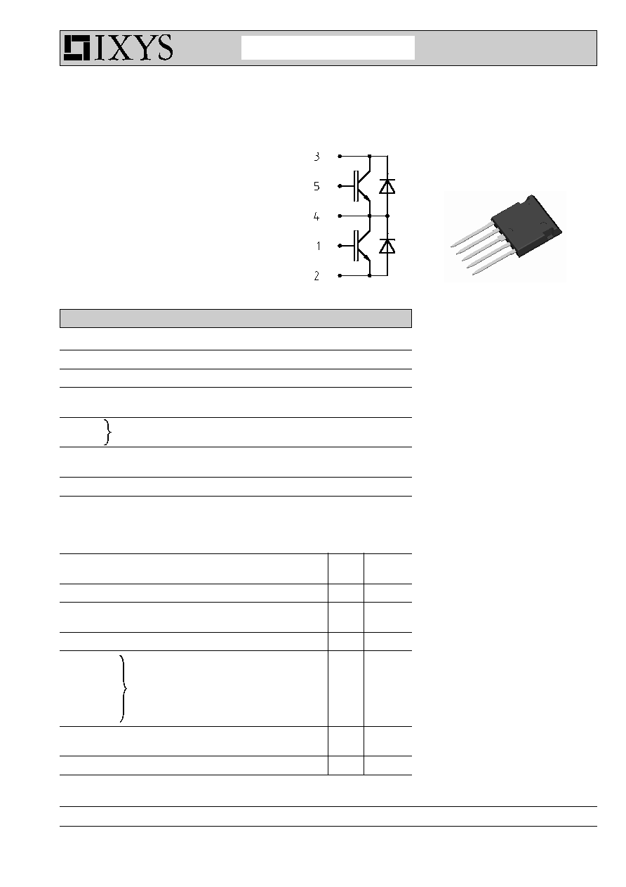
FII 30-12D
Features
∑ NPT IGBT
- low saturation voltage
- no latch up
- positive temperature coefficient for
easy paralleling
∑ HiPerFRED
TM
diode
- fast reverse recovery
- low operating forward voltage
- low leakage current
∑ ISOPLUS i4-PAC
TM
package
- isolated back surface
- enlarged creepage towards heatsink
- application friendly pinout
- low inductive current path
- high reliability
- industry standard outline
Applications
∑ single phaseleg
- buck-boost chopper
∑ H bridge
- power supplies
- induction heating
- four quadrant DC drives
- controlled rectifier
∑ three phase bridge
- AC drives
- controlled rectifier
IGBT
Symbol
Conditions
Maximum Ratings
V
CES
T
VJ
= 25∞C to 150∞C
1200
V
V
GES
±
20
V
I
C25
T
C
= 25∞C
30
A
I
C90
T
C
= 90∞C
18
A
I
CM
V
GE
=
±
15 V; R
G
= 82
; T
VJ
= 125∞C
35
A
V
CEK
RBSOA, Clamped inductive load; L = 100 µH
V
CES
t
SC
V
CE
= V
CES
; V
GE
=
±
15 V; R
G
= 82
; T
VJ
= 125∞C
10
µs
(SCSOA)
non-repetitive
P
tot
T
C
= 25∞C
125
W
Symbol
Conditions
Characteristic Values
(T
VJ
= 25
∞
C, unless otherwise specified)
min.
typ.
max.
V
CE(sat)
I
C
= 20 A; V
GE
= 15 V; T
VJ
= 25∞C
2.3
3.0
V
T
VJ
= 125∞C
2.6
V
V
GE(th)
I
C
= 0.6 mA; V
GE
= V
CE
4.5
6.5
V
I
CES
V
CE
= V
CES
;
V
GE
= 0 V; T
VJ
= 25∞C
0.9
mA
T
VJ
= 125∞C
0.9
mA
I
GES
V
CE
= 0 V; V
GE
=
±
20 V
200
nA
t
d(on)
100
ns
t
r
75
ns
t
d(off)
500
ns
t
f
70
ns
E
on
3.0
mJ
E
off
2.4
mJ
C
ies
V
CE
= 25 V; V
GE
= 0 V; f = 1 MHz
1000
pF
Q
Gon
V
CE
= 600V; V
GE
= 15 V; I
C
= 18 A
70
nC
R
thJC
1.0 K/W
Inductive load, T
VJ
= 125∞C
V
CE
= 600 V; I
C
= 20 A
V
GE
= ±15 V; R
G
= 82
I
C25
= 30 A
V
CES
= 1200 V
V
CE(sat) typ.
= 2.3 V
Fast IGBT Chopper
in ISOPLUS i4-PAC
TM
1
5
Advanced Technical Information
IXYS Semiconductor GmbH
Edisonstr. 15,
D-68623 Lampertheim
Phone: +49-6206-503-0, Fax: +49-6206-503627
IXYS Corporation
3540 Bassett Street, Santa Clara CA 95054
Phone: (408) 982-0700, Fax: 408-496-0670
