© 2004 IXYS All rights reserved
1 - 2
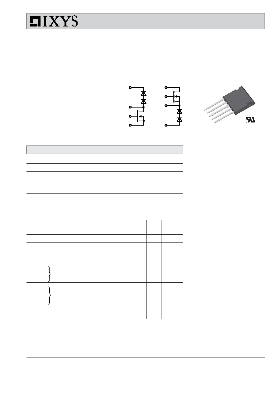
FMD 21-05QC
FDM 21-05QC
439
IXYS reserves the right to change limits, test conditions and dimensions.
I
D25
= 21 A
V
DSS
= 500 V
R
DSon typ.
= 190 m
Q-Class
Power MOSFETs
Chopper Topologies
in ISOPLUS i4-PAC
TM
Features
∑ Q-Class Power MOSFET technology
- low R
DSon
- low gate charge for high frequency
operation
- unclamped inductive switching (UIS)
capability
- dv/dt ruggedness
∑ HiPerDyn
TM
FRED
- consisting of series connected diodes
- enhanced dynamic behaviour for
high frequency operation
∑ ISOPLUS i4-PAC
TM
package
- isolated back surface
- UL registered E72873
- low coupling capacity
between pins and heatsink
- enlarged creepage towards heatsink
- application friendly pinout
- low inductive current path
- high reliability
- industry standard outline
Applications
∑ chopper for power factor correction
∑ supply of high frequency transformer
- switched mode power supplies
- welding converters
Preliminary data
3
4
5
2
MOSFET
Symbol
Conditions
Maximum Ratings
V
DSS
T
VJ
= 25∞C to 150∞C
500
V
V
GS
±20
V
I
D25
T
C
= 25∞C
21
A
I
D90
T
C
= 90∞C
15
A
Symbol
Conditions
Characteristic Values
(T
VJ
= 25
∞C, unless otherwise specified)
min.
typ.
max.
R
DSon
V
GS
= 10 V;
I
D
= I
D90
220 m
V
GSth
V
DS
= 20 V;
I
D
= 0.25 mA
2.5
4.5
V
I
DSS
V
DS
= V
DSS
;
V
GS
= 0 V; T
VJ
= 25∞C
250
µA
T
VJ
= 125∞C
250
µA
I
GSS
V
GS
= ±20 V; V
DS
= 0 V
200
nA
Q
g
95
nC
Q
gs
20
nC
Q
gd
42
nC
t
d(on)
20
ns
t
r
20
ns
t
d(off)
50
ns
t
f
15
ns
R
thJC
0.5 K/W
R
thJH
with heat transfer paste
0.93
K/W
V
GS
= 10 V; V
DS
= 0.5 ∑ V
DSS
; I
D
= 14 A
V
GS
= 10 V; V
DS
= 0.5 ∑ V
DSS
I
D
= 14 A; R
G
= 2
1
5
FDM
FMD
3
4
1
2

© 2004 IXYS All rights reserved
2 - 2
FMD 21-05QC
FDM 21-05QC
439
Dimensions in mm (1 mm = 0.0394")
Component
Symbol
Conditions
Maximum Ratings
T
VJ
-55...+150
∞C
T
stg
-55...+125
∞C
V
ISOL
I
ISOL
1 mA; 50/60 Hz
2500
V~
F
C
mounting force with clip
20...120
N
Symbol
Conditions
Characteristic Values
min.
typ.
max.
C
p
coupling capacity between shorted pins
40
pF
and mounting tab in the case
d
S
,d
A
pin - pin
1.7
mm
d
S
,d
A
pin - backside metal
5.5
mm
Weight
9
g
Free Wheeling Diode (data for series connection)
Symbol
Conditions
Maximum Ratings
V
RRM
T
VJ
= 25∞C to 150∞C
600
V
I
F25
T
C
= 25∞C
60
A
I
F90
T
C
= 90∞C
40
A
Symbol
Conditions
Characteristic Values
min.
typ.
max.
V
F
I
F
= 15 A; T
VJ
= 25∞C
2.5
2.8
V
T
VJ
= 125∞C
1.9
V
I
R
V
R
= V
RRM
; T
VJ
= 25∞C
0.13 mA
T
VJ
= 125∞C
0.13
mA
I
RM
I
F
= 30 A; di
F
/dt = -500 A/µs; T
VJ
= 125∞C
9
A
t
rr
V
R
= 300 V
40
ns
R
thJC
0.65 K/W
R
thJH
with heat transfer paste
1.3
K/W