 | –≠–ª–µ–∫—Ç—Ä–æ–Ω–Ω—ã–π –∫–æ–º–ø–æ–Ω–µ–Ω—Ç: L558 | –°–∫–∞—á–∞—Ç—å:  PDF PDF  ZIP ZIP |

1 - 5
© 2003 IXYS All rights reserved
IXYS reserves the right to change limits, test conditions and dimensions.
308
VWI 20-06P1
Features
∑ NPT IGBT's
- positive temperature coefficient of
saturation voltage
- fast switching
∑ FRED diodes
- fast reverse recovery
- low forward voltage
∑ Industry Standard Package
- solderable pins for PCB mounting
- isolated DCB ceramic base plate
Typical Applications
∑ AC drives
∑ power supplies with power factor
correction
IGBTs
Symbol
Conditions
Maximum Ratings
V
CES
T
VJ
= 25∞C to 150∞C
600
V
V
GES
±
20
V
I
C25
T
C
= 25∞C
19
A
I
C80
T
C
= 80∞C
14
A
I
CM
V
GE
= ±15 V; R
G
= 82
; T
VJ
= 125∞C
20
A
V
CEK
RBSOA, Clamped inductive load; L = 100 µH
V
CES
t
SC
V
CE
= 720 V; V
GE
= ±15 V; R
G
= 82
; T
VJ
= 125∞C
10
µs
(SCSOA)
non-repetitive
P
tot
T
C
= 25∞C
73
W
Symbol
Conditions
Characteristic Values
(T
VJ
= 25
∞
C, unless otherwise specified)
min.
typ.
max.
V
CE(sat)
I
C
= 10 A; V
GE
= 15 V; T
VJ
= 25∞C
1.9
2.4
V
T
VJ
= 125∞C
2.2
V
V
GE(th)
I
C
= 0.35 mA; V
GE
= V
CE
4.5
6.5
V
I
CES
V
CE
= V
CES
;
V
GE
= 0 V; T
VJ
= 25∞C
0.6
mA
T
VJ
= 125∞C
2.7
mA
I
GES
V
CE
= 0 V; V
GE
=
±
20 V
100
nA
t
d(on)
35
ns
t
r
35
ns
t
d(off)
230
ns
t
f
30
ns
E
on
0.4
mJ
E
off
0.3
mJ
C
ies
V
CE
= 25 V; V
GE
= 0 V; f = 1 MHz
600
pF
Q
Gon
V
CE
= 300 V; V
GE
= 15 V; I
C
= 10 A
39
nC
R
thJC
(per IGBT)
1.7 K/W
R
thJH
with heatsink compound (0.42 K/m.K; 50 µm)
3.4
K/W
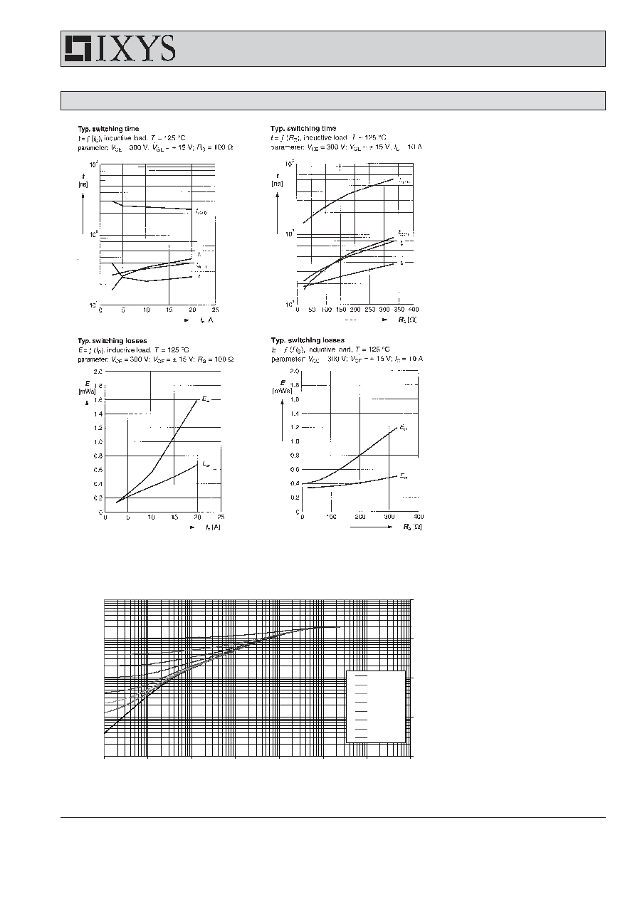
Inductive load, T
VJ
= 125∞C
V
CE
= 300 V; I
C
= 10 A
V
GE
= ±15 V; R
G
= 82
I
C25
= 19 A
V
CES
= 600 V
V
CE(sat) typ.
= 1.9 V
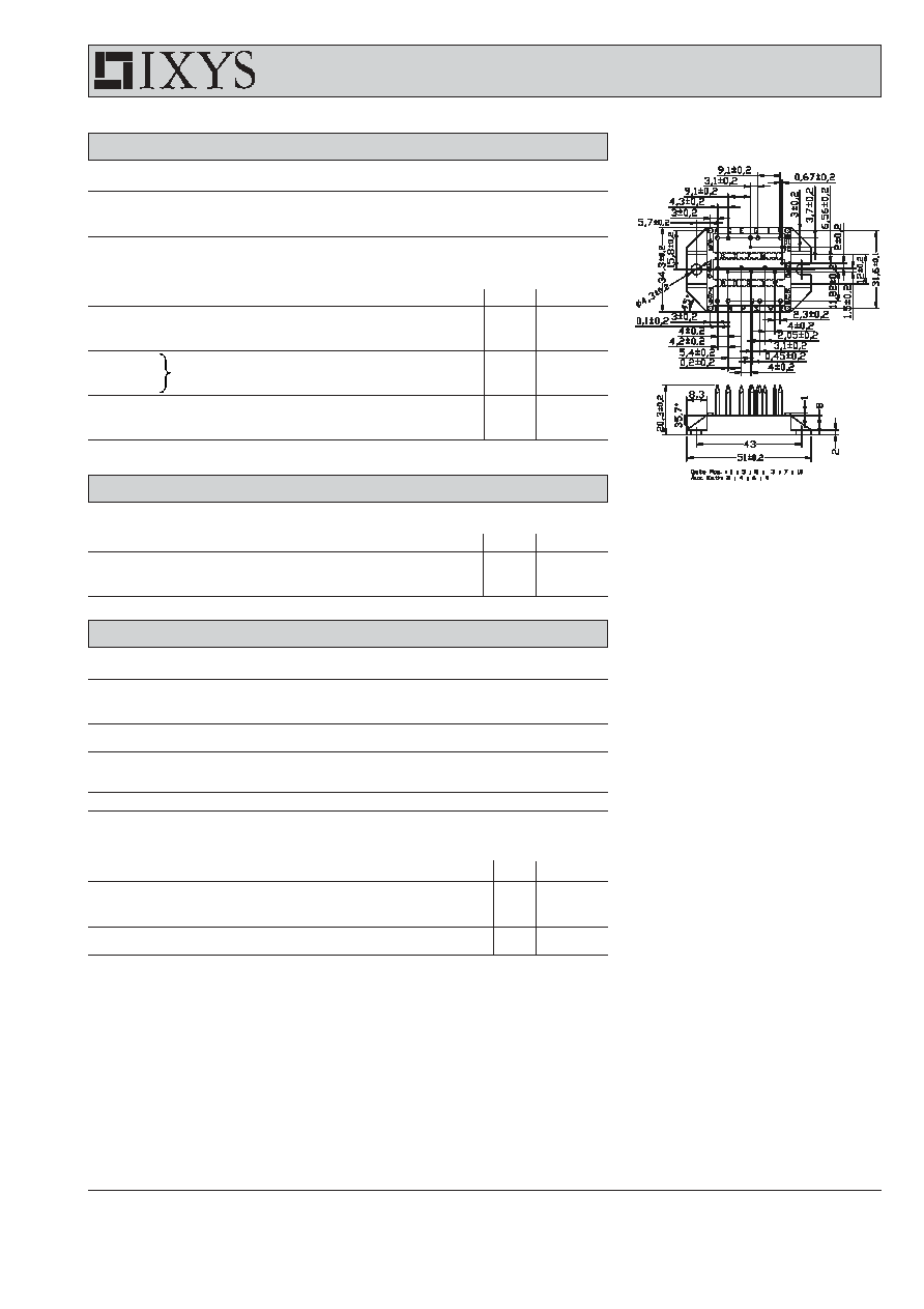
IGBT Module
Sixpack in ECO-PAC 2
IXYS Semiconductor GmbH
Edisonstr. 15,
D-68623 Lampertheim
Phone: +49-6206-503-0, Fax: +49-6206-503627
IXYS Corporation
3540 Bassett Street, Santa Clara CA 95054
Phone: (408) 982-0700, Fax: 408-496-0670
www.ixys.net
S 9
G 1
L 9
N 5
A 1
F 3
C 1
X 18
W 14
K 10
N 9
R 5
D 5
A 5
H 5
Pin arangement see outlines
K 12
J 13
NTC
Preliminary data
2 - 5
© 2003 IXYS All rights reserved
IXYS reserves the right to change limits, test conditions and dimensions.
308
VWI 20-06P1
Dimensions in mm (1 mm = 0.0394")
Diodes
Symbol
Conditions
Maximum Ratings
I
F25
T
C
= 25∞C
21
A
I
F80
T
C
= 80∞C
14
A
Symbol
Conditions
Characteristic Values
min.
typ.
max.
V
F
I
F
= 10 A; T
VJ
= 25∞C
1.9
2.1
V
T
VJ
= 125∞C
1.4
V
I
RM
I
F
= 10 A; di
F
/dt = -400 A/µs; T
VJ
= 125∞C
11
A
t
rr
V
R
= 300 V; V
GE
= 0 V
80
ns
R
thJC
3.5 K/W
R
thJH
with heatsink compound (0.42 K/m.K; 50 µm)
7.0
K/W
Component
Symbol
Conditions
Maximum Ratings
T
VJ
-40...+150
∞
C
T
stg
-40...+125
∞
C
V
ISOL
I
ISOL
1 mA; 50/60 Hz; t = 1 s
3600
V~
M
d
mounting torque (M4)
1.5 - 2.0
Nm
14 - 18
lb.in.
a
Max. allowable acceleration
50
m/s
2
Symbol
Conditions
Characteristic Values
min. typ.
max.
d
S
Creepage distance on surface
(Pin to heatsink)
11.2
mm
d
A
Strike distance in air
(Pin to heatsink)
11.2
mm
Weight
24
g
Data according to IEC 60747 and refer to a single diode unless otherwise stated.
Temperature Sensor NTC
Symbol
Conditions
Characteristic Values
min.
typ.
max.
R
25
T = 25∞C
4.75
5.0
5.25 k
B
25/50
3375
K

3 - 5
© 2003 IXYS All rights reserved
IXYS reserves the right to change limits, test conditions and dimensions.
308
VWI 20-06P1
IGBT
4 - 5
© 2003 IXYS All rights reserved
IXYS reserves the right to change limits, test conditions and dimensions.
308
VWI 20-06P1
Transient thermal resistance junction to heatsink
(Z
thJH
is measured using 50 µm
thermal grease)
IGBT
Z
thJH
[K/W]
0.001
0.01
0.1
1
10
0.00001
0.0001
0.001
0.01
0.1
1
10
100
t (s)
D = 0
D = 0.005
D = 0.01
D = 0.02
D = 0.05
D = 0.1
D = 0.2
D = 0.5
IGBT

5 - 5
© 2003 IXYS All rights reserved
IXYS reserves the right to change limits, test conditions and dimensions.
308
VWI 20-06P1
Transient thermal resistance junction to heatsink
200
600
1000
0
400
800
70
80
90
100
110
120
0
40
80
120
160
0.0
0.5
1.0
1.5
2.0
K
f
T
VJ
∞C
-di
F
/dt
0
200
400
600
800
1000
0
5
10
15
20
0.0
0.3
0.6
0.9
1.2
V
FR
di
F
/dt
V
200
600
1000
0
400
800
0
10
20
30
40
100
1000
0.0
0.2
0.4
0.6
0.8
1.0
1.2
1.4
0.0
0.5
1.0
1.5
2.0
2.5
0
5
10
15
20
25
30
I
RM
Q
r
I
F
A
V
F
-di
F
/dt
-di
F
/dt
A/
µ
s
A
V
nC
A/
µ
s
A/
µ
s
t
rr
ns
t
fr
A/
µ
s
µ
s
I
F
= 20A
I
F
= 10A
I
F
= 5A
T
VJ
= 100∞C
V
R
= 300V
T
VJ
= 100∞C
I
F
= 10A
Peak reverse current I
RM
versus -di
F
/dt
Reverse recovery charge Q
r
versus -di
F
/dt
Forward current I
F
versus V
F
T
VJ
= 100∞C
V
R
= 300V
T
VJ
= 100∞C
V
R
= 300V
I
F
= 20A
I
F
= 10A
I
F
= 5A
Q
r
I
RM
Dynamic parameters Q
r
, I
RM
versus T
VJ
Recovery time t
rr
versus -di
F
/dt
Peak forward voltage V
FR
and t
fr
versus di
F
/dt
I
F
= 20A
I
F
= 10A
I
F
= 5A
t
fr
V
FR
T
VJ
=150∞C
T
VJ
=100∞C
T
VJ
= 25∞C
8-06A
(Z
thJH
is measured using 50 µm
thermal grease)
Fred
Z
thJH
[K/W]
0.001
0.01
0.1
1
10
0.00001
0.0001
0.001
0.01
0.1
1
10
100
t(s)
D = 0
D = 0.005
D = 0.01
D = 0.02
D = 0.05
D = 0.1
D = 0.2
D = 0.5
Diode