© 2002 IXYS All rights reserved
1 - 2
IXYS reserves the right to change limits, test conditions and dimensions.
VUE 130-12NO7
241
B3
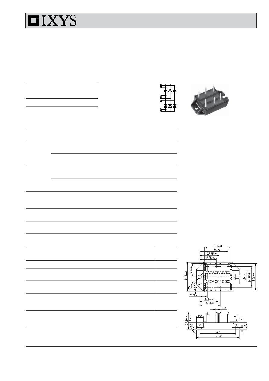
Three Phase Rectifier Bridge
with Fast Recovery Epitaxial Diodes (FRED)
in ECO-PAC 2
I
dAV
= 130 A
V
RRM
= 1200 V
t
rr
= 40 ns
V
RSM
V
RRM
Typ
V
V
1200
1200
VUE 130-12NO7
Symbol
Conditions
Maximum Ratings
I
dAV
T
C
= 70∞C, module
130
A
I
dAVM
90
A
I
FSM
T
VJ
= 45∞C
t = 10 ms (50 Hz), sine
500
A
V
R
= 0
t = 8.3 ms (60 Hz), sine
525
A
T
VJ
= T
VJM
t = 10 ms (50 Hz), sine
415
A
V
R
= 0
t = 8.3 ms (60 Hz), sine
440
A
I
2
t
T
VJ
= 45∞C
t = 10 ms (50 Hz), sine
1250
A
2
s
V
R
= 0
t = 8.3 ms (60 Hz), sine
1160
A
2
s
T
VJ
= T
VJM
t = 10 ms (50 Hz), sine
860
A
2
s
V
R
= 0
t = 8.3 ms (60 Hz), sine
820
A
2
s
T
VJ
-40...+150
∞C
T
VJM
150
∞C
T
stg
-40...+125
∞C
V
ISOL
50/60 Hz, RMS
t = 1 min
3000
V~
I
ISOL
1 mA
t = 1 s
3600
V~
M
d
Mounting torque (M4)
1.5-2/14-18
Nm/lb.in.
Weight
typ.
24
g
Features
∑ Package with DCB ceramic
base plate in low profile
∑ Isolation voltage 3000 V~
∑ Planar passivated chips
∑ Low forward voltage drop
∑ Leads suitable for PC board soldering
Applications
∑ Supplies for DC power equipment
∑ Input and output rectifiers for high
frequency
∑ Battery DC power supplies
∑ Field supply for DC motors
Advantages
∑ Space and weight savings
∑ Improved temperature and power
cycling capability
∑ Small and light weight
∑ Low noise switching
Data according to IEC 60747 refer to a single diode unless otherwise stated
for resistive load at bridge output.
Symbol
Conditions
Characteristic Values
typ.
max.
I
R
V
R
= V
RRM
T
VJ
= 25∞C
1
mA
V
R
= V
RRM
T
VJ
= T
VJM
2.5
mA
V
F
I
F
= 60 A
T
VJ
= 25∞C
2.7
V
V
T0
for power-loss calculations only
1.07
V
r
T
8.2 m
R
thJC
per diode; DC current
0.8 K/W
R
thCH
per diode, DC current, typ.
0.2 K/W
I
RM
I
F
= 130 A, -diF/dt = 100 A/µs
7
15
A
V
R
= 100 V, T
VJ
= 100∞C
t
rr
I
F
= 1 A; -di/dt = 300 A/µs; V
R
= 30 V, T
VJ
= 25∞C
40
ns
a
Max. allowable acceleration
50
m/s
2
d
S
creeping distance on surface (pin to heatsink)
11.2
mm
d
A
strike distance in air (pin to heatsink)
9.7
mm
Dimensions in mm (1 mm = 0.0394")
Preliminary data sheet
PS16
EG 1
~
A 1
~
L 9
~
K10
Pin arangement see outlines
© 2002 IXYS All rights reserved
2 - 2
IXYS reserves the right to change limits, test conditions and dimensions.
VUE 130-12NO7
241
B3
200
600
1000
0
400
800
160
200
240
280
0,0001
0,001
0,01
0,1
1
10
0,01
0,1
1
0
40
80
120
160
0,0
0,5
1,0
1,5
2,0
K
f
T
VJ
C
-di
F
/dt
t
s
K/W
0
200
400
600
800
1000
0
40
80
120
0,0
0,4
0,8
1,2
V
FR
di
F
/dt
V
200
600
1000
0
400
800
0
20
40
60
80
100
100
1000
0
2
4
6
8
10
0
1
2
3
0
20
40
60
80
100
I
RM
Q
r
I
F
A
V
F
-di
F
/dt
-di
F
/dt
A/
µ
s
A
V
µ
C
A/
µ
s
A/
µ
s
t
rr
ns
t
fr
A/
µ
s
µ
s
Z
thJC
DWLP55-12
DWLP55-12
DWLP55-12
VUE130-12
DWLP55-12
I
RM
Q
r
DWLP55-12
t
fr
V
FR
DWLP55-12
T
VJ
= 150∞C
T
VJ
= 100∞C
T
VJ
= 25∞C
T
VJ
= 100∞C
V
R
= 600 V
T
VJ
= 100∞C
V
R
= 600 V
I
F
= 30 A
I
F
= 15 A
I
F
= 7.5 A
I
F
= 30 A
I
F
= 15 A
I
F
= 7.5 A
T
VJ
= 100∞C
V
R
= 600 V
T
VJ
= 100∞C
V
R
= 15 A
I
F
= 30 A
I
F
= 15 A
I
F
= 7.5 A
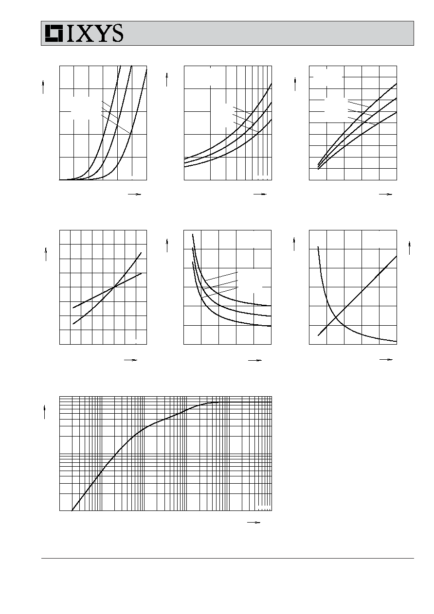
Fig. 3 Peak reverse current I
RM
versus -di
F
/dt
Fig. 2 Reverse recovery charge Q
r
versus -di
F
/dt
Fig. 1 Forward current I
F
versus V
F
Fig. 4 Dynamic parameters Q
r
, I
RM
versus T
VJ
Fig. 5 Recovery time t
rr
versus -di
F
/dt
Fig. 6 Peak forward voltage V
FR
and t
fr
versus di
F
/dt
Fig. 7 Typical transient thermal resistance junction to case
NOTE: Fig. 2 to Fig. 6 shows typical values