
1 - 2
© 2004 IXYS All rights reserved
FMD 80-0045PS
406
IXYS reserves the right to change limits, test conditions and dimensions.
I
D25
= 100 A
V
DSS
= 55 V
R
DSon (typ.)
= 3.8 m
Chopper with
Trench Power MOSFET
and Schottky Diode
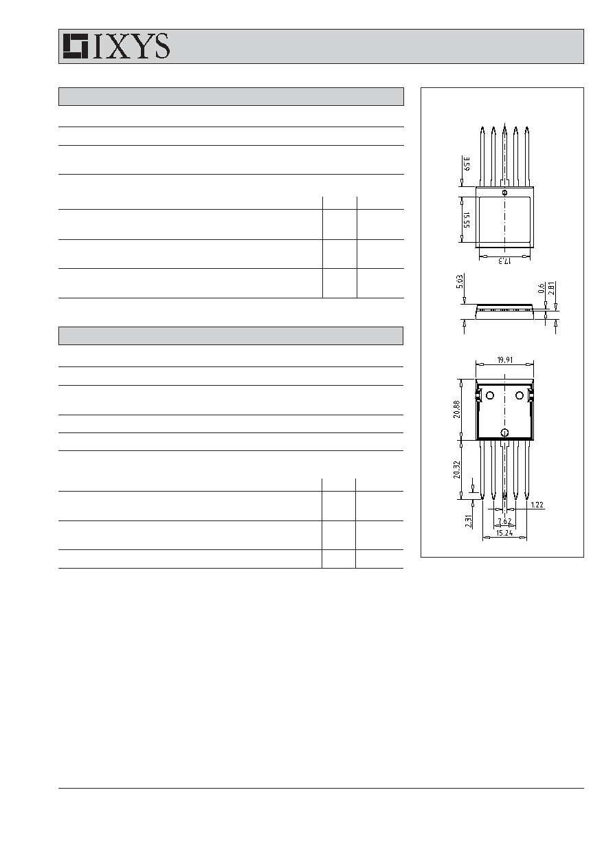
in ISOPLUS i4-PAC
TM
1
5
Features
∑ trench MOSFET
- very low on state resistance R
DSon
- fast switching
∑ Schottky diode
- low forward voltage
- extremely fast switching
- blocking capability optimized for
elevated temperature
∑ ISOPLUS i4-PAC
TM
package
- isolated back surface
- low coupling capacity between pins
and heatsink
- enlarged creepage towards heatsink
- application friendly pinout
- low inductive current path
- high reliability
- industry standard outline
- UL registered, E 72873
Applications
∑ automotive
- choppers - replacing series resistors
for DC drives, heating etc.
- control of SR drives
- DC-DC converters
- electronic switches -replacing relays
and fuses
∑ power supplies
- DC-DC converters
- solar inverters
∑ battery supplied systems
- choppers for drives in hand held tools
- battery chargers
IXYS Semiconductor GmbH
Edisonstr. 15,
D-68623 Lampertheim
Phone: +49-6206-503-0, Fax: +49-6206-503627
IXYS Corporation
3540 Bassett Street, Santa Clara CA 95054
Phone: (408) 982-0700, Fax: 408-496-0670
MOSFET
Symbol
Conditions
Maximum Ratings
V
DSS
T
VJ
= 25∞C to 150∞C
55
V
V
GS
±20
V
I
D25
T
C
= 25∞C
150
A
I
D90
T
C
= 90∞C
110
A
Symbol
Conditions
Characteristic Values
(T
VJ
= 25
∞C, unless otherwise specified)
min.
typ.
max.
R
DSon
V
GS
= 10 V;
I
D
= I
D90
3.8
4.9 m
V
GSth
V
DS
= 20 V;
I
D
= 1 mA
2
4
V
I
DSS
V
DS
= 55V;
V
GS
= 0 V; T
VJ
= 25∞C
1
µA
T
VJ
= 125∞C
0.1
mA
I
GSS
V
GS
= ±20 V; V
DS
= 0 V
0.2
µA
Q
g
86
nC
Q
gs
18
nC
Q
gd
25
nC
t
d(on)
25
ns
t
r
50
ns
t
d(off)
70
ns
t
f
40
ns
R
thJC
1 K/W
R
thJH
with heatsink compound
1.5
K/W
V
GS
= 10 V; V
DS
= 44 V; I
D
= 25 A
V
GS
= 10 V; V
DS
= 30 V;
I
D
= 25A; R
G
= 10
3
4
1
2
Preliminary data
2 - 2
© 2004 IXYS All rights reserved
FMD 80-0045PS
406
IXYS reserves the right to change limits, test conditions and dimensions.
Dimensions in mm (1 mm = 0.0394")
Component
Symbol
Conditions
Maximum Ratings
I
RMS
per pin
75
A
T
VJ
-55...+175
∞C
T
stg
-55...+125
∞C
V
ISOL
I
ISOL
1 mA; 50/60 Hz
2500
V~
F
C
mounting force with clip
20...120
N
Symbol
Conditions
Characteristic Values
min.
typ.
max.
C
P
coupling capacity between shorted
40
pF
pins and mounting tab in the case
d
S
,d
A
pin - pin
1.7
mm
d
S
,d
A
pin - backside metal
5.5
mm
Weight
9
g
Schottky Diode
Symbol
Conditions
Maximum Ratings
V
RRM
T
VJ
= 25∞C to 150∞C
45
V
I
F25
T
C
= 25∞C
110
A
I
F90
T
C
= 90∞C
80
A
Symbol
Conditions
Characteristic Values
min.
typ.
max.
V
F
I
F
= 40 A; T
VJ
= 25∞C
0.9
V
T
VJ
= 125∞C
0.7
V
I
R
V
R
= V
RRM
;
T
VJ
= 25∞C
0.5
mA
T
VJ
= 125∞C
1
mA
R
thJC
1.5 K/W
R
thJH
with heatsink compound
1.9
K/W