 | –≠–ª–µ–∫—Ç—Ä–æ–Ω–Ω—ã–π –∫–æ–º–ø–æ–Ω–µ–Ω—Ç: UGD6123AG | –°–∫–∞—á–∞—Ç—å:  PDF PDF  ZIP ZIP |
High Voltage rectifiers
Hochspannungs-
gleichrichter
Reg. Nr. 2743-02
Edition 97

2
„
1997 IXYS All rights reserved
Symbols and Definitions
a
Acceleration
I
F(AV)M
Maximum mean forward
current
I
F(RMS)
Maximum RMS forward current
I
FSM
Surge forward current
I
R
Repetitive peak reverse current
M
d
Mounting torque
P
RSM
Maximum surge reverse power dissipation
r
T
Forward slope resistance
(for power loss calculations only)
T
amb
Ambient temperature or temperature of the
cooling medium
T
stg
Storage temperature
T
(vj)
Viritual junction temperature
V
dT
DC voltage at V
V(RMS)
arithmetic mean
V
F
Forward voltage
V
RRM
Maximum repetitive peak
reverse
voltage
V
V(RMS)
Supply voltage, RMS value
V
TO
Threshold voltage
(for power loss calculations only)
a
R¸ttelfestigkeit
I
F(AV)M
Maximaler Durchlaþstrom-Mittelwert
I
F(RMS)
Hˆchstzul‰ssiger Effektiv-Durchlaþstrom
I
FSM
Maximaler Stoþstrom
I
R
Sperrstrom
M
d
Anzugsdrehmoment
P
RSM
Maximale Stoþsperrverlustleistung
r
T
Ersatzwiderstand
(nur zur Berechnung der Verlustleistung)
T
amb
Umgebungstemperatur oder
K¸hlmitteltemperatur
T
stg
Lagertemperatur
T
(vj)
Sperrschichttemperatur
V
dT
Typgleichspannung bei V
V(RMS)
arithm. Mittelwert
V
F
Durchlaþspannung
V
RRM
Hˆchstzul. periodische Spitzensperrspannung
V
V(RMS)
Typische Anschluþspannung (Effektivwert)
V
TO
Schleusenspannung
(nur zur Berechnung der Verlustleistung)
Kurzzeichen und Begriffe
Example: UGE 0421 AY4
U
High Voltage rectifier, U-Series
G
Uncontrolled rectifier
E
One way circuit
B
One phase bridge circuit
D
Three phase bridge circuit
Code, number of power semiconductors
0
1- 4
1
5- 6
2
7-12
4
Code, max. average forward
current in A
1 < 3 A; 2 < 12 A; 3 < 16 A; 4 < 33 A etc.
2
Code, type of built in power
semiconductors
1
Code, max. RMS voltage
1 > 1 KV; 2 > 2 KV; 3 > 3 KV etc.
A
Letter, A = avalanche diode
Y4 Version (see dimension drawing)
Y4 = round housing, A-N = plastic housing
Nomenclature for High Voltage Rectifiers
Beispiel: UGE 0421 AY4
U
Hochspannungs-Gleichrichter, Baureihe U
G
Ungesteuerter Gleichrichter
E
Einwegschaltung
B
Einphasen-Br¸ckenschaltung
D
Dreiphasen-Br¸ckenschaltung
Kennziffer, Anzahl der Leistungshalbleiter
0
1- 4
1
5- 6
2
7-12
4
Kennziffer, Dauergrenzstrom in A
1 < 3 A; 2 < 12 A; 3 < 16 A; 4 < 33 A usw.
2
Kennziffer, Art der eingebauten Dioden
1
Kennziffer, Anschluþspannung
1 > 1 KV; 2 > 2 KV; 3 > 3 KV usw.
A
Buchstabe, A = Avalanche-Diode
Y4 Geh‰usebauform (siehe Maþbild)
Y4 = runder Becher, A-N = Kunststoff-
becher
3
IXYS reserve the right to change limits, test conditions and dimensions.
Contents/Inhalt
Page
Seite
Symbols and Definitions / Kurzzeichen und Begriffe
2
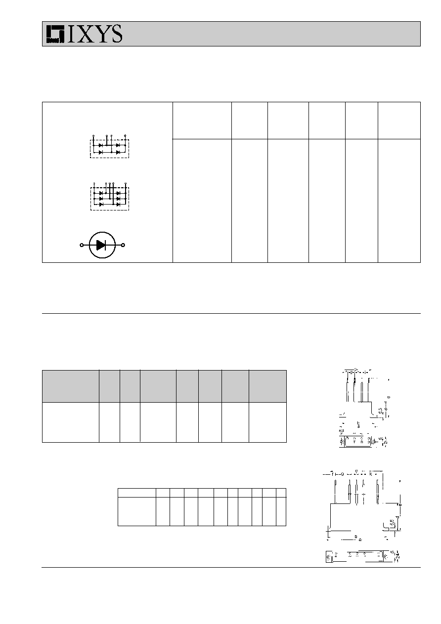
Typ
V
RRM
V
V(RMS)
I
F(AV)M
I
FSM
T
(vj)m
Weight Dimensions
45
∞
∞
∞
∞
∞
C
Gewicht
Maþbild
10 ms
V
V
A
A
∞
∞
∞
∞
∞
C
UGB 3132 AD
4800
2250
1.3
60
150
150
1
UGB 6124 AG
10500
5000
1.0
50
150
300
1
UGD 6123 AG
7200
3300
1.8
50
150
300
2
UGD 8124 AG
10500
5000
1.2
50
150
300
2
1
2
Typ
a
b
c
d
e
f
g
h
i
k
UGB 3132 AD
80
70
57
58.5
260
6
15
15 15
UGB 6124 AG
135
125
112
58.5
260
11
32.5 25 32.5
UGB 6123 AG
135
125
112
58.5
260
8
30
18 18
30
UGB 8124 AG
135
125
112
58.5
260
8
30
18 18
30
Type
V
RRM
V
V(RMS)
I
F(AV)M
I
FSM
Typ
45
∞
C
10 ms
V
V
A
A
UGB 3132 AD
4800
2250
1.3
60
3
UGB 6124 AG
10500
5000
1.0
50
3
UGD 6123 AG
7200
3300
1.8
50
3
UGD 8124 AG
10500
5000
1.2
50
3
UGE 0421 AY4
3200
1125
23/7.4
300
4 - 5
UGE 0221 AY4
4800
1750
10/3.8
180
6 - 7
UGE 1112 AY4
8000
3000
4.2/2.0
120
8 - 9
UGE 3126 AY4
24000
9000
2.0/0.8
70
10 - 11
UGB
Circuit configuration
Schaltbild
Technical data, application notes
/ Technische Daten, Applikationshinweise
12 - 13
Mounting instructions
/ Montagehinweise
15 - 15
IXYS International Sales Representatives
16
UGD
1~ / 3~ High Voltage Rectifier Modules
Hochspannungs-Gleichrichter-Module

4
Dimensions in mm (1 mm = 0.0394")
Anode
Kathode
Features
q
Hermetically sealed Epoxy
q
Use in oil
q
Avalanche characteristics
Applications
q
X-Ray equipment
q
Electrostatic dust precipitators
q
Electronic beam welding
q
Lasers
q
Cable test equipment
Advantages
q
Simple mounting
q
Improved temperature and power
cycling
q
Reduced protection circuits
q
Series and parallel operation
„
1997 IXYS All rights reserved
Data according to IEC 747-2
Symbol
Test Conditions
Ratings
I
F(RMS)
40
A
I
F(AV)M
air self cooling,
T
amb
= 45∞C
- without cooling plate
7.4
A
- with colling plate
10.9
A
forced air cooling:
v = 3 m/s,
T
amb
= 35∞C
- without cooling plate
14.2
A
- with cooling plate
18.8
A
oil cooling,
T
amb
= 35∞C
- without cooling plate
19.7
A
- with cooling plate
22.9
A
P
RSM
T
(vj)
= 150∞C;
t
p
= 10 µs
7
kW
I
FSM
non repetitive, 50 c/s
(for 60 c/s add 10%)
T
(vj)
= 45∞C;
t
p
= 10 ms
300
A
T
(vj)
= 150∞C;
t
p
= 10 ms
250
A
T
amb
-40...+150
∞C
T
stg
-40...+150
∞C
T
(vj)
150
∞C
Weight
115
g
Symbol
Test Conditions
Characteristic Values
I
R
T
(vj)
= 150∞C;
V
R
= V
RRM
2
mA
V
F
I
F
=
55 A
2.72
V
T
(vj)
=
25∞C
V
TO
T
(vj)
= 150∞C
1.7
V
r
T
T
(vj)
= 150∞C
16
m
a
f
=
50Hz
5 x 9,81
m/s
2
M
d
8
Nm
High Voltage Rectifiers
V
RRM
= 3200 V
Hochspannungsgleichrichter
V
dT
=
500 V
I
F(AV)M
= 22.9 A
V
RRM
V
V(RMS)
V
dT
Standard
Power Designation
V
V
V
Types
3200
1125
500
UGE 0421 AY4
Si-E 1125 / 500-6
UGE 0421 AY4

5
IXYS reserve the right to change limits, test conditions and dimensions.
Fig. 1: Forward characteristics
Instantaneous forward current I
F
as a function of instantaneous forward
voltage drop V
F
for junction temperature T
(vj)
= 25∞C and T
(vj)
= 150∞C
a = Mean value characteristic
b = Limit value characteristic
Fig. 2: Characteristics of maximum permissible current
The curves show the non repetitive peak one cycle surge forward
current I
FSM
as a function of time
t and serve for rating protective
devices.
a = Initial state
T
(vj)
= 45∞C
b = Initial state
T
(vj)
= 150∞C
Fig. 3: Power loss
Non repetitive peak reverse power loss P
RSM
as a function of time
t,
T
(vj)
= 150∞C
Fig. 4: Load diagramm
Mean forward current I
F(AV)
of one module for a sine half wave for various
cooling modes as a function of the cooling medium temperature T
amb
for a
resistive load (horizontal mounting).
Cooling modes
1 = air self cooling
without cooling plate
2 = air self cooling
with
cooling plate
3 = forced air cooling
without cooling plate
4 = forced air cooling
with
cooling plate
5 = oil cooling
without cooling plate
6 = oil cooling
with
cooling plate
10
-6
10
-5
10
-4
10
-3
10
-2
10
2
10
3
10
4
s
t
W
P
RSM
0.4
1.2
2.0
2.8
3.6
0
20
40
60
80
100
V
V
F
A
I
F
a
b
10
-3
10
-2
10
-1
10
0
10
1
0
50
100
150
200
250
300
s
t
A
I
FSM
0
20
40
60
80
100 120 140
0
10
20
30
∞C
T
A
A
I
F(AV)
4
3
2
1
6
5
180∞
I
FAV
T(vj) = 150∞C
T(vj) = 25∞C
b
a
UGE 0421 AY4

6
Dimensions in mm (1 mm = 0.0394")
Anode
Kathode
Features
q
Hermetically sealed Epoxy
q
Use in oil
q
Avalanche characteristics
Applications
q
X-Ray equipment
q
Electrostatic dust precipitators
q
Electronic beam welding
q
Lasers
q
Cable test equipment
Advantages
q
Simple mounting
q
Improved temperature and power
cycling
q
Reduced protection circuits
q
Series and parallel operation
„
1997 IXYS All rights reserved
Data according to IEC 747-2
Symbol
Test Conditions
Ratings
I
F(RMS)
16
A
I
F(AV)M
air self cooling,
T
amb
= 45∞C
- without cooling plate
3.8
A
- with colling plate
5.4
A
forced air cooling:
v = 3 m/s,
T
amb
= 35∞C
- without cooling plate
7.0
A
- with cooling plate
10.2
A
oil cooling,
T
amb
= 35∞C
- without cooling plate
10.2
A
- with cooling plate
10.2
A
P
RSM
T
(vj)
= 150∞C;
t
p
= 10 µs
3.4
kW
I
FSM
non repetitive, 50 c/s
(for 60 c/s add 10%)
T
(vj)
= 45∞C;
t
p
= 10 ms
180
A
T
(vj)
= 150∞C;
t
p
= 10 ms
140
A
T
amb
-40...+150
∞C
T
stg
-40...+150
∞C
T
(vj)
150
∞C
Weight
120
g
Symbol
Test Conditions
Characteristic Values
I
R
T
(vj)
= 150∞C;
V
R
= V
RRM
2
mA
V
F
I
F
=
30 A
4.8
V
T
(vj)
=
25∞C
V
TO
T
(vj)
= 150∞C
2.55
V
r
T
T
(vj)
= 150∞C
90
m
a
f
=
50Hz
5 x 9,81
m/s
2
M
d
8
Nm
High Voltage Rectifiers
V
RRM
= 4800 V
Hochspannungsgleichrichter
V
dT
=
775 V
I
F(AV)M
= 10.2 A
V
RRM
V
V(RMS)
V
dT
Standard
Power Designation
V
V
V
Types
4800
1750
775
UGE 0221 AY4
Si-E 1750 / 775-4
UGE 0221 AY4

7
IXYS reserve the right to change limits, test conditions and dimensions.
Fig. 1: Forward characteristics
Instantaneous forward current I
F
as a function of instantaneous forward
voltage drop V
F
for junction temperature T
(vj)
= 25∞C and T
(vj)
= 150∞C
a = Mean value characteristic
b = Limit value characteristic
Fig. 2: Characteristics of maximum permissible current
The curves show the non repetitive peak one cycle surge forward
current I
FSM
as a function of time
t and serve for rating protective
devices.
a = Initial state
T
(vj)
= 45∞C
b = Initial state
T
(vj)
= 150∞C
Fig. 3: Power loss
Non repetitive peak reverse power loss P
RSM
as a function of time
t,
T
(vj)
= 150∞C
Fig. 4: Load diagramm
Mean forward current I
F(AV)
of one module for a sine half wave for various
cooling modes as a function of the cooling medium temperature T
amb
for a
resistive load (horizontal mounting).
Cooling modes
1 = air self cooling
without cooling plate
2 = air self cooling
with
cooling plate
3 = forced air cooling
without cooling plate
4 = forced air cooling
with
cooling plate
5 = oil cooling
without cooling plate
6 = oil cooling
with
cooling plate
0
30
60
90
120
150
0
2
4
6
8
10
∞C
T
A
A
I
F(AV)
0,6 1,2 1,8 2,4 3,0 3,6 4,2 4,8 5,4
0
10
20
30
40
V
V
F
A
I
F
10
-3
10
-2
10
-1
10
0
10
1
0
50
100
150
200
s
t
A
I
FSM
a
b
a
b
10
-6
10
-5
10
-4
10
-3
10
-2
10
2
10
3
10
4
s
t
W
P
RSM
180∞
I
FAV
6
5
4
3
2
1
T(vj) = 150∞C
T(vj) = 25∞C
UGE 0221 AY4

8
Dimensions in mm (1 mm = 0.0394")
Anode
Kathode
Features
q
Hermetically sealed Epoxy
q
Use in oil
q
Avalanche characteristics
Applications
q
X-Ray equipment
q
Electrostatic dust precipitators
q
Electronic beam welding
q
Lasers
q
Cable test equipment
Advantages
q
Simple mounting
q
Improved temperature and power
cycling
q
Reduced protection circuits
q
Series and parallel operation
„
1997 IXYS All rights reserved
Data according to IEC 747-2
Symbol
Test Conditions
Ratings
I
F(RMS)
7
A
I
F(AV)M
air self cooling,
T
amb
= 45∞C
- without cooling plate
2.0
A
- with colling plate
2.5
A
forced air cooling:
v = 3 m/s,
T
amb
= 35∞C
- without cooling plate
3.2
A
- with cooling plate
4.1
A
oil cooling,
T
amb
= 35∞C
- without cooling plate
4.2
A
- with cooling plate
4.2
A
P
RSM
T
(vj)
= 150∞C;
t
p
= 10 µs
2.5
kW
I
FSM
non repetitive, 50 c/s
(for 60 c/s add 10%)
T
(vj)
= 45∞C;
t
p
= 10 ms
120
A
T
(vj)
= 150∞C;
t
p
= 10 ms
100
A
T
amb
-40...+150
∞C
T
stg
-40...+150
∞C
T
(vj)
150
∞C
Weight
122
g
Symbol
Test Conditions
Characteristic Values
I
R
T
(vj)
= 150∞C;
V
R
= V
RRM
1
mA
V
F
I
F
=
7 A
6.25
V
T
(vj)
=
25∞C
V
TO
T
(vj)
= 150∞C
4.25
V
r
T
T
(vj)
= 150∞C
0.215
m
a
f
=
50Hz
5 x 9,81
m/s
2
M
d
8
Nm
High Voltage Rectifiers
V
RRM
= 8000 V
Hochspannungsgleichrichter
V
dT
= 1300 V
I
F(AV)M
= 4.2 A
V
RRM
V
V(RMS)
V
dT
Standard
Power Designation
V
V
V
Types
8000
3000
1300
UGE 1112 AY4
Si-E 3000 / 1300-2.5
UGE 1112 AY4

9
IXYS reserve the right to change limits, test conditions and dimensions.
Fig. 1: Forward characteristics
Instantaneous forward current I
F
as a function of instantaneous forward
voltage drop V
F
for junction temperature T
(vj)
= 25∞C and T
(vj)
= 150∞C
a = Mean value characteristic
b = Limit value characteristic
Fig. 2: Characteristics of maximum permissible current
The curves show the non repetitive peak one cycle surge forward
current I
FSM
as a function of time
t and serve for rating protective
devices.
a = Initial state
T
(vj)
= 45∞C
b = Initial state
T
(vj)
= 150∞C
Fig. 3: Power loss
Non repetitive peak reverse power loss P
RSM
as a function of time
t,
T
(vj)
= 150∞C
Fig. 4: Load diagramm
Mean forward current I
F(AV)
of one module for a sine half wave for various
cooling modes as a function of the cooling medium temperature T
amb
for a
resistive load (horizontal mounting).
Cooling modes
1 = air self cooling
without cooling plate
2 = air self cooling
with
cooling plate
3 = forced air cooling
without cooling plate
4 = forced air cooling
with
cooling plate
5 = oil cooling
without cooling plate
6 = oil cooling
with
cooling plate
0
30
60
90
120
150
0
1
2
3
4
5
∞C
T
A
A
I
F(AV)
3,0 3,5 4,0 4,5 5,0 5,5 6,0 6,5
0
2
4
6
8
10
V
V
F
A
I
F
10
-3
10
-2
10
-1
10
0
10
1
0
20
40
60
80
100
120
s
t
A
I
FSM
10
-6
10
-5
10
-4
10
-3
10
-2
10
1
10
2
10
3
10
4
s
t
W
P
RSM
a
T(vj) = 150∞C
T(vj) = 25∞C
b
a
b
180∞
I
FAV
5+6
4
3
2
1
UGE 1112 AY4

10
Dimensions in mm (1 mm = 0.0394")
Anode
Kathode
Features
q
Hermetically sealed Epoxy
q
Use in oil
q
Avalanche characteristics
Applications
q
X-Ray equipment
q
Electrostatic dust precipitators
q
Electronic beam welding
q
Lasers
q
Cable test equipment
Advantages
q
Simple mounting
q
Improved temperature and power
cycling
q
Reduced protection circuits
q
Series and parallel operation
„
1997 IXYS All rights reserved
Data according to IEC 747-2
Symbol
Test Conditions
Ratings
I
F(RMS)
5
A
I
F(AV)M
air self cooling,
T
amb
= 45∞C
- without cooling plate
0.8
A
- with colling plate
1.0
A
forced air cooling:
v = 3 m/s,
T
amb
= 35∞C
- without cooling plate
1.4
A
- with cooling plate
1.7
A
oil cooling,
T
amb
= 35∞C
- without cooling plate
2.0
A
- with cooling plate
2.0
A
P
RSM
T
(vj)
= 150∞C;
t
p
= 10 µs
1.6
kW
I
FSM
non repetitive, 50 c/s
(for 60 c/s add 10%)
T
(vj)
= 45∞C;
t
p
= 10 ms
70
A
T
(vj)
= 150∞C;
t
p
= 10 ms
60
A
T
amb
-40...+150
∞C
T
stg
-40...+150
∞C
T
(vj)
150
∞C
Weight
127
g
Symbol
Test Conditions
Characteristic Values
I
R
T
(vj)
= 150∞C;
V
R
= V
RRM
1
mA
V
F
I
F
=
3 A
18
V
T
(vj)
=
25∞C
V
TO
T
(vj)
= 150∞C
12
V
r
T
T
(vj)
= 150∞C
1.8
m
a
f
=
50Hz
5 x 9,81
m/s
2
M
d
8
Nm
High Voltage Rectifiers
V
RRM
= 24000 V
Hochspannungsgleichrichter
V
dT
= 4000 V
I
F(AV)M
=
2.0 A
V
RRM
V
V(RMS)
V
dT
Standard
Power Designation
V
V
V
Types
24000
9000
4000
UGE 1112 AY4
Si-E 9000 / 4000-0.7
UGE 3126 AY4
Data according to IEC 747-2

11
IXYS reserve the right to change limits, test conditions and dimensions.
Fig. 1: Forward characteristics
Instantaneous forward current I
F
as a function of instantaneous forward
voltage drop V
F
for junction temperature T
(vj)
= 25∞C and T
(vj)
= 150∞C
a = Mean value characteristic
b = Limit value characteristic
Fig. 2: Characteristics of maximum permissible current
The curves show the non repetitive peak one cycle surge forward
current I
FSM
as a function of time
t and serve for rating protective
devices.
a = Initial state
T
(vj)
= 45∞C
b = Initial state
T
(vj)
= 150∞C
Fig. 3: Power loss
Non repetitive peak reverse power loss P
RSM
as a function of time
t,
T
(vj)
= 150∞C
Fig. 4: Load diagramm
Mean forward current I
F(AV)
of one module for a sine half wave for various
cooling modes as a function of the cooling medium temperature T
amb
for a
resistive load (horizontal mounting).
Cooling modes
1 = air self cooling
without cooling plate
2 = air self cooling
with
cooling plate
3 = forced air cooling
without cooling plate
4 = forced air cooling
with
cooling plate
5 = oil cooling
without cooling plate
6 = oil cooling
with
cooling plate
0
30
60
90
120
150
0
1
2
3
∞C
T
A
A
I
F(AV)
10
-3
10
-2
10
-1
10
0
10
1
0
10
20
30
40
50
60
70
80
90
100
s
t
A
I
FSM
0 2 4 6 8 10 12 14 16 18 20 22 24
0
1
2
3
4
5
6
7
8
9
10
V
V
F
A
I
F
10
-6
10
-5
10
-4
10
-3
10
-2
10
-1
10
0
10
1
10
2
10
3
10
4
s
t
W
P
RSM
T(vj) = 150∞C
T(vj) = 25∞C
a
b
b
a
180∞
I
FAV
6
4
3
1
2
5
UGE 3126 AY4

12
„
1997 IXYS All rights reserved
1.
General remarks
The high-voltage retifier modules of the UGE series function
as single-leg half-wave rectifiers (abbreviation = E). They are
used for high-voltage DC supply, e.g. in
≠ high frequency generators
≠ X-ray equipment
≠ dust precipitators.
The construction of the module plastic case with screw
connection simplifies mechanical arrangement of the desired
rectifier circuit.
The user's individual input voltage and current requirements
can be satisfied by selection of the appropriate modules, by
mounting with or without a cooling plate or by series connection
of modules.
2.
Design
2.1 Electrical
High-voltage rectifier modules consist of an internally integrated
series connection of avalanche diodes.
Electric terminals of the module screw connection:
Anode (A)
= Threaded hole
Cathode (K)
= Threaded bolt
2.2 Mechanical
(for dimensions see dimension diagram)
The avalanche diodes are embedded in an epoxy resin pot
with axial metal terminals. The materials used guarantee good
insulation and resistance to corrosion.
3.
Technical data
The operating reliability of high-voltage rectifier modules is
mainly influenced by the safety margin between the specified
limit values and the operating data. Table on page 3 gives rated
voltage values - recommended voltages with a frequency of
40 to 60 Hz and a maximum voltage variation of 10% - for the
single leg circuit configuration.
When other rectifier circuits are arranged with these modules
V
dT
becomes:
≠ bridge circuit, B
V
dT
= 0,9 x V
V(RMS)
≠ three phase bridge circuit, DB
V
dT
= 1,35 = V
V(RMS)
1.
Allgemeines
Die Hochspannungsgleichrichter-Module der Serie UGE sind
in ihrer elektrischen Funktion Einweggleichrichter in Einzweig-
schaltung (Kurzbezeichnung = E). Sie werden zur Hoch-
spannungs-Gleichstromversorgung eingesetzt, z.B. in
≠ Hochfrequenz-Generatoren
≠ Rˆntgenanlagen
≠ elektrostatischen Staubfilteranlagen.
Die Modulkonstruktion - Kunststoffgeh‰use mit Schraub-
verbindung - ermˆglicht einen einfachen mechanischen Auf-
bau der gew¸nschten Gleichrichterschaltung.
Anwendungsspezifische Anschluþspannungen und Strˆme
kˆnnen durch Auswahl der geeigneten Bausteine, Montage
ohne und mit K¸hlblech bei verschiedenen K¸hlarten oder durch
Serienschaltung verwirklicht werden.
2.
Aufbau
2.1 Elektrisch
Hochspannungsgleichrichter-Module bestehen aus einer in-
tegrierten Reihenschaltung von Avalanche-Dioden.
Elektrische Anschl¸sse der Modul-Schraubverbindung:
Anode (A)
= Gewindebohrung
Kathode (K)
= Gewindebolzen.
2.2 Mechanisch
(Abmessungen siehe Maþbild)
In einem Epoxydharzbecher mit axial angeordneten Metallan-
schl¸ssen sind die Avalanche-Dioden in Gieþharz eingebettet.
Die verwendeten Materialien garantieren eine gute Isolations-
f‰higkeit und Korrosionsbest‰ndigkeit.
3.
Technische Daten
Die Betriebszuverl‰ssigkeit von Hochspannungsgleichrichter-
Modulen wird wesentlich durch den Sicherheitsabstand zwi-
schen den angegebenen Grenzwerten und den Einsatzdaten
beeinfluþt. F¸r die spannungsm‰þige Beanspruchung in Ein-
zweigschaltung sind in der Tabelle Seite 3 Nennwerte - das
sind empfohlene Betriebsdaten, die f¸r sinusfˆrmige Ver-
sorgungsspannung von 40 bis 60 Hz und maximal 10%
Spannungsschwankung gelten - angegeben.
Bei Aufbau von anderen Gleichrichterschaltungen mit diesen
Modulen ergibt sich V
dT
entsprechen:
≠ Br¸ckenschaltung, B
V
dT
= 0,9 x V
V(RMS)
≠ Drehstrom-Br¸ckenschaltung, DB
V
dT
= 1,35 = V
V(RMS)

13
IXYS reserve the right to change limits, test conditions and dimensions.
50
7
50
100
The current reduction factors apply for air self cooling and horizontal mounting (with
respect to module axis).
Die Stromreduzierungsfaktoren gelten bei Luftselbstk¸hlung nur f¸r waagrechte Ein-
baulage (bezogen auf Modulachse).
Table 2:
Current reduction factor S
n
Tabelle 2: Stromreduzierungsfaktor S
n
8.4
5.4
120
7
4.
Current reduction for series connections
When several modules are connected in series (screwed to
one another), the allowed mean forward current I
FAV
should be
reduced as a function of the number of modules and cooling
mode used.
Cooling modes
1 = Convection cooling
without cooling plate
2 = Convection cooling
with
cooling plate
3 = Forced air cooling
without cooling plate
4 = Forced air cooling
with
cooling plate
5= Oil cooling
without cooling plate
6 = Oil cooling
with
cooling plate
4.
Stromreduktion bei Reihenschaltung
Bei Serienschaltung (Aneinanderschrauben) mehrerer Modu-
le ist der zul‰ssige Dauergrenzstrom IFAV in Abh‰ngigkeit von
der Anzahl der Module und K¸hlart zu reduzieren.
Definition der K¸hlarten
1 = Luftselbstk¸hlung
ohne K¸hlblech
2 = Luftselbstk¸hlung
mit K¸hlblech
3 = Verst‰rkte Luftk¸hlung ohne K¸hlblech
4 = Verst‰rkte Luftk¸hlung mit K¸hlblech
5 = ÷lk¸hlung
ohne K¸hlblech
6 = ÷lk¸hlung
mit K¸hlblech
3 mm thick aluminium plate, chamfer all edges.
Aluminium-Blech, 3 mm dick, alle Kanten brechen.
no further
reduction
keine weitere
Reduktion
Cooling mode
Number of modules
K¸hlart
Anzahl Module
2 3 4
5
6
>7
S
n
1
0,75
0,65
0,6
0,55
0,5
2
0,85
0,8
0,78
0,75
3
0,85
0,8
0,78
0,77
4
0,95
0,92
0,9
0,88
5
0,92
0,88
0,86
6
0,96
0,94

14
„
1997 IXYS All rights reserved
Insulation class
Isolationsgruppe
A
B
C
Construction
without with
without with
without with
Cooling plate
Cooling plate
Cooling plate
Aufbauart
ohne mit
ohne mit
ohne mit
K¸hlblech
K¸hlblech
K¸hlblech
Allowed supply voltage
based creepage distance
[V]
[V]
[V]
[V]
[V]
[V]
Zul‰ssige Anschluþspannung
9000
7600
6900
4900
5000
3400
aufgrund des Kriechwegs
Table 3
Tabelle 3
not included in scope of delivery
gehˆrt nicht zum Lieferumfang
Spring washer B 8 DIN 137 A 2 g
Federscheibe B 8 DIN 137 A 2 g
Washer A 8,5
DIN 125 ≠ ST-A4G
Scheibe A 8,5
DIN 125 ≠ ST-A4G
Apply thermal grease DC 340 here when mounting with cooling plates
Bei Montage mit K¸hlblechen hier W‰rmeleitpaste DC 340 auftragen
M
Fig. 7: Mounting of modules
Bild 7: Montage der Module
Torque M = 800 Ncm
Drehmoment M = 800 Ncm
5.
Mounting instructions
5.1 Mounting of modules
without cooling plate (Fig. 7):
5.
Montagehinweise
5.1 Darstellung der Montage:
Montage ohne K¸hlblech (Bild 7)
5.2 Mounting of modules
with cooling plate:
as shown in Fig. 7, however, the cooling plate ist mounted with
thermal grease instead of with washer A 8.5
DIN 125.
To satisfy VDE specification 0110, voltage limits are prescribed
- depending on the creepage distance of the pot shape (61
mm for mounting without cooling plate, 42 mm for mounting
with cooling plate). In case of air cooling care should be taken
that the proper class of insulation is chosen for the respective
supply voltage (see table 3).
5.2 Montage:
Module mit K¸hlblech
wie in Bild 7 skizziert, jedoch anstelle der Scheibe A 8,5
DIN
125 wird das K¸hlblech mit W‰rmeleitpaste eingesetzt.
Zur Einhaltung der VDE-Vorschrift 0110 sind - bedingt durch
den Kriechweg der Bechergeometrie (61 mm bei Montage ohne
K¸hlblech, 42 mm bei Montage mit K¸hlblech) - Spannungs-
grenzen vorgeschrieben. Zu beachten ist bei Betrieb in Luft,
daþ sich die zul‰ssige Anschluþspannung nach der vorgese-
henen Isolationsgruppe richtet (siehe Tabelle 3).
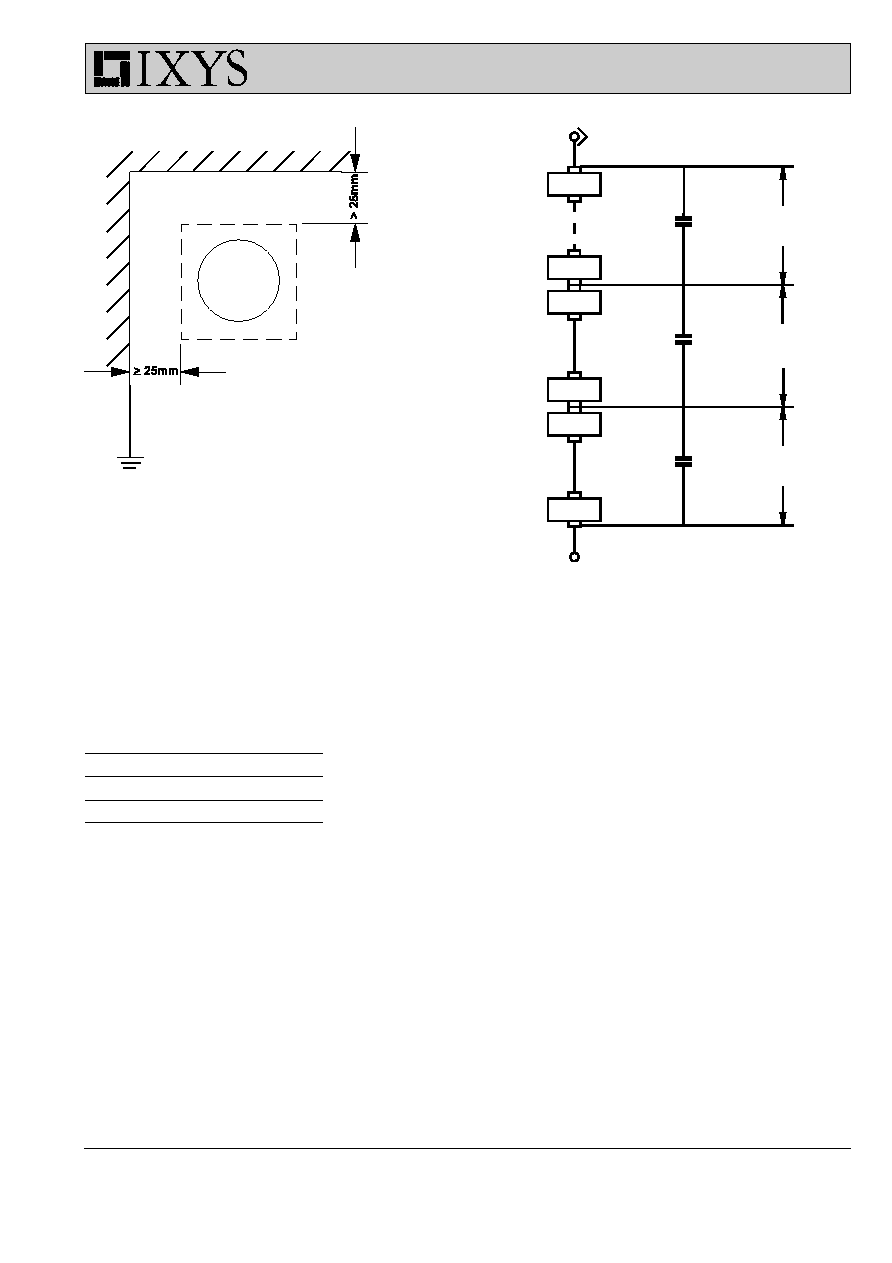
5.3 Distance to adjacent parts
The distance to adjacent g metal parts should be at least 25
mm. This also applies to mounting with cooling plates (see Fig.
8).
A protective circuit in accordance with Table 4 should be
provided in order to prevent unpermissible capacitive earth
currents from flowing through the first diode. This can be done
by arranging the modules in groups for voltages of Vp ~ 30 kV
each (see Fig. 9).
5.3 Abst‰nde zur Umgebung
Der Abstand zu umgebenden geerdeten Metall-Teilen sollte
minimal 25 mm betragen. Dies gilt auch bei Aufbau mit K¸hl-
blechen (siehe Bild 8).
Zur Vermeidung von unzul‰ssigen kapazitiven Erdstrˆmen ¸ber
die erste Diode ist eine Schutzbeschaltung nach Tabelle 4 vor-
zusehen. Es sind dabei jeweils Modulgruppen f¸r Teilspannun-
gen von Vp ~ 30 kV zu bilden (siehe Bild 9).
15
IXYS reserve the right to change limits, test conditions and dimensions.
Fig. 9: Circuit for protection of modules against capacitive earth currents
Bild 9: Schutzbeschaltung der Module gegen kapazitive Erdstrˆme
C
I
(nF)
UGE 0421 AY4
5.6
UGE 0221 AY4
2.2
UGE 1112 AY4
0.87
UGE 3126 AY4
0.15
Table 4: Protective circuit capacitances for avoidance of too high capacitive ground currents from 30 kV
RMS
Tabelle 4: Schutzbeschaltungskapazit‰ten zur Vermeidung zu groþer kapazitiver Erdstrˆme ab 30 kV
RMS
Fig. 8: Minimum distance for mounting
Bild 8: Mindestabst‰nde bei Montage
UGE ....
C
1
C
1
C
1
~ 30 kV
~ 30 kV
~ 30 kV
UGE ....

IXYS Semiconductor GmbH
Edisonstr. 15, D-68623 Lampertheim
Telefon: +49-6206-503-0, Fax: +49-6206-503627
e-mail: custserv@ixys.de
IXYS Corporation
3540 Bassett Street, Santa Clara CA 95054
Phone: (408) 982-0700, Fax: 408-496-0670
http://www.ixys.com
e-mail: sales@ixys.com
Publication D 97008 DE
Printed in Germany (09.97 ∑ 2 ∑ DP)
Technical advice and further information
IXYS International Sales Representatives
Germany (Reps)
Asia, Australia, Africa
North
Hubert Schroeter KG
Saseler Bogen 1
22393 Hamburg
Phone:
040/6 00 006-0
Fax:
040/6 00 006-30
West
Erhard Mannheim KG
Industrievertretungen
Heidestraþe 4
42579 Heiligenhaus
Phone:
02056/9 83 60
Fax:
02056/5 74 37
Southwest
Wolfgang Trautmann
Reutlinger Str. 4
78054 VS-Schwenningen
Phone:
07720/12 03
Fax:
07720/3 34 42
Germany
(Distris)
Kluxen GmbH
Nordkanal 52
20097 Hamburg 1
Phone:
040/23 70 15 29
Fax:
040/23 03 85
Dietrich Schuricht
GmbH & Co. KG
Richtweg 32
28195 Bremen
Phone:
0421/36 54 54
Fax:
0421/36 54 291
BETRONIK Handelsgesellschaft
f¸r elektronische Bauelemente mbH
Grunewaldstr. 39a
12165 Berlin
Phone:
030/79 09 97 - 0
Fax:
030/79 09 97 51
Ingenieurb¸ro
Rainer Kˆnig
Giesendorfer Str. 11 a
12207 Berlin
Phone:
030/76 89 09 16
Fax:
030/76 89 09 30
MSC Vertriebs GmbH
Industriestraþe 16
76297 Stutensee
Phone:
07249/910-0
Fax:
07249/79 93
Future Electronics
Deutschland GmbH
M¸nchner Straþe 18
85774 Unterfˆhring
Phone:
089/95 72 70
Fax:
089/95 72 71 29
Sparepart-Service
ABB Industrietechnik AG
Gesch‰ftsbereich Service
Edisonstr. 15
68623 Lampertheim
Phone:
06206/503 272
Fax:
06206/503 620
IXYS Semiconductor GmbH
Edisonstr. 15
68623 Lampertheim
Phone:
06206/503 394
Fax:
06206/503 627
Europe
Austria
ABB Serienprodukte Ges.m.b.H.
Abt. SERTQ
Wienerbergstraþe 11 B
P.O. Box 184
1101 Wien
Phone: 01-60 10 9-6153
Fax:
01-60 10 9-8600
Denmark
C-88 AS
Kokkedal Industripark 101
2980 Kokkedal
Phone: +45-70 10 48 88
Fax:
+45-70 10 48 89
Finland
Energel Oy
Atomitie 1
00370 Helsinki
Phone: 0-586 2066
Fax:
0-586 2046
France
Eurocomposant S.A.
144 Avenue Joseph Kessel
78960 Voisins le Bretonneux
Phone: 1-30 64 95 15
Fax:
1-30 43 68 27
Greece
Markides Michelis & Co
8, Markris Str., Aegaleo
122 41 Athens
Phone: 1-5 98 01 45
Fax:
1-5 90 98 33
Great Britain
IXYS Semiconductor GmbH
Providence House
Forest Road, Binfield
Bracknell,
Berkshire RG 12 5HP
Phone: 01344-48 28 20
Fax:
01344-48 28 10
Great Britain
GD Rectifiers Ltd.
Victoria Gardens
Burgess Hill
West Sussex RH159NB
Phone: 01444-24 34 52
Fax:
01444-87-07-22
Great Britain
Larontrol Ltd.
Unit K4 Brookside Avenue
Rustington Trading Estate
Littlehampton
West Sussex BN16 3LF
Phone: 01903-77 11 60
Fax:
01903-77 20 73
Great Britain
Future Electronics
Poyle Road, Colnbrook
Berkshire SL3 OEZ
Phone: 01753-68 70 00
Fax:
01753-68 91 00
Italy
ABB DACOM SpA
Viale Edison, 50
20099 Sesto San Giovanni (MI)
Phone: 02-26 232.125
Fax:
02-26 232.144
Australia
Braemac PTY. Ltd.
1/59-61 Burrows Road
Alexandria NSW 2015
Phone:
(02) 9550 6600
Fax:
(02) 9550 6370
China
KARIN Electronic Supplies
Room 1095, Pana Tower
36 Hai Dian Road
Hai Dian District, Beijing
Phone:
8610-6262 9049
Fax:
8610-6264 8830
China
KARIN Electronic Supplies
Room 305, A Section,
Yin Hai Bldg., 250 Cao Xi Rd.
Shanghai
Phone:
8621-6482 3543
Fax:
8632-6482 3542
China
KARIN Electronic Supplies
Room 1503, Oriental Plaza
39 Janshe Rd, Shenzhen
Phone:
86755-220 9219
Fax:
86755-228 4992
China
Sunguard Electronics Ltd.
Room 112, No. 12B
Zhong Guan Chun Road
Hai Dian District, Beijing
Phone:
10-264-5210,
10-264-5212 + 10-254-2870
Fax:
10-254-2870
China
Sunguard Electronics Ltd.
Room 805, 8/F.,
Sufa Building, Block 306
ZhenHua Road, Shenzhen
Phone:
0755-3230 748 (658)
0755-3237 349
Fax:
0755-3237 394
Hongkong
KARIN Electronic Supplies
Co. Ltd., Div. 8
KARIN Building, 5F
166 Wai Yip St., Kwun Tong
Kowloon, Hong Kong
Phone:
852-2763 3100
Fax:
852-2343 6479
Hongkong
RÍvel Electronics Co. Ltd.
Unit 11, 12/Floor, Ricky Centre
36 Chong Yip Street, Kwun Tong
Kowloon, Hong Kong
Phone:
23 89-88 91
Fax:
23 89-24 48
Hongkong
Sunguard Electronics Ltd.
907-10 Yat Chau, International Plaza
118 Connaught Road West
Hong Kong
Phone:
(852) 2811 8230
Fax:
(852) 2960 1239,
2960 1216
India
Chadda Power Semiconductors
501, Savera Apts.
Versova Road, Andheri (West)
Bombay-400 061
Phone:
022-6 26 06 78
Fax:
022-6 31 63 84
Netherlands
ABB Componenten B.V.
Lylantse Baan 9
2908 LG Capelle a/d IJssel
Phone: 010-2 58 22 50
Fax:
010-4 58 65 59
Norway
Henaco A/S
Trondheimsveien 436
Po. box 126, Kalbakken
0902 Oslo 9
Phone: 2-216 21 10
Fax:
2-225 77 80
Sweden
Pelcon Electronics AB
Girov‰gen 13
Box 6023
17562 J‰rf‰lla
Phone: 8-7 95 98 70
Fax:
8-7 60 76 85
Switzerland
ABB Normelec AG
Badenerstr. 790
8048 Z¸rich-Altstetten
Phone: 1-4 35 66 66
Fax:
1-4 35 66 06
Spain
ABI Semiconductores
Dalia 387 Ch 6
28109 El Soto (Alcobendas)
Phone: 91-6 50 76 51
Fax:
91-6 50 03 49
Spain
AQL electrÛnica, s.a.
General Palanca, 26
28045 Madrid
Phone: 91-4 67 75 12
Fax:
91-5 30 29 34
Spain
Rectificadores Guasch S.A.
Componentes y Electronica de
Potencia
Alaba, 60-62
08005 Barcelona
Phone: 93-3 09 88 91
Fax:
93-3 00 18 41
Turkey
÷zdisan Elektronik Pazarlama
San. VE TIC. A.S.
Bereketzade Mahallesl
Galata Kulesi Sokak No: 34/3
Karakˆy/Istanbul
Phone: 212-243 40 34, 251 29 41
Fax:
212-244 59 43
Israel
Gallium Electronics Ltd.
11 Hasadna St.
P.O.B. 2552
IL 43650 RA'ANANA
Phone:
972 9 74 82 182
Fax:
972 9 74 84 046
Japan
Unidux Inc.
5-1-21 Kyonan-cho,
Musashino-shi, Tokyo 180
Phone:
0422-32-4500
Fax:
0422-31-2050
Japan
Systems Marketing, Inc.
Fukui Bldg. 2-2-12
Sotokanda, Chiyoda-Ku
Tokyo 101
Phone:
03-32 54 27 51
Fax:
03-32 54 32 88
Japan
Trancy INC
New Heights Aoyama 203
1-1-10 Shibuya,
Shibuya-Ku Tokyo 150
Phone:
+81-3-3486-7211
Fax:
+81-3-3486-7214
Korea
Asea Brown Boveri Ltd.
Oksan Bldg. 5-9 Fl.
157, Samsung-Dong,
Kangnam-Ku, Seoul 135-090
Phone:
2-52 83 062
Fax:
2-52 83 091
Korea
Kisung International Co. Ltd.
A-7-121, 604-1
Kuro-Dong, Kuro-Ku, Seoul
Phone:
02-679 7348
Fax:
02-675 1404
Korea
Daan Electronic Co., Ltd.
Daan Bldg, 4F
22-1 Singye-Dong,
Yongsan-Ku, Seoul
Phone:
02-822-718-8033
Fax:
02-822-718 1160+1161
Singapore
Practical Electronics Pte. Ltd.
1 Rochor Canal Rd
# 02-57, Sim Lim Square
Singapore 0718
Phone:
3-38 73 88
Fax:
3-38 16 88
South Africa
ABB Industry (Pty) Ltd. Drives
P.O. Box 11494, Randhart 1457
Phone:
011-8 64 53 40
Fax:
011-9 08 20 61
South Africa
Avnet Kopp (Pty) Ltd
P. O. Box 3853, Rivonia, 2128
South Africa.
Phone:
+27 11 444 2333
Fax:
+27 11 444 7778
Taiwan
Industrade Co., Ltd.
6F, No. 64, Section 2
Chung Cheng Road
Shihlin, Taipei, Taiwan 111
Phone:
886-2-836 90 11
Fax:
886-2-835 30 37
Sept. 97