
© 2000 IXYS All rights reserved
1 - 2
Symbol
Test Conditions
Maximum Ratings
I
dAV
T
C
= 100
∞
C
(diode)
20
A
I
dAV
x
(module)
40
A
I
FSM
T
VJ
= 45
∞
C;
t = 10 ms (50 Hz), sine
300
A
V
R
= 0
t = 8.3 ms (60 Hz), sine
320
A
T
VJ
= T
VJM
t = 10 ms (50 Hz), sine
260
A
V
R
= 0
t = 8.3 ms (60 Hz), sine
280
A
I
2
t
T
VJ
= 45
∞
C
t = 10 ms (50 Hz), sine
450
A
2
s
V
R
= 0
t = 8.3 ms (60 Hz), sine
430
A
2
s
T
VJ
= T
VJM
t = 10 ms (50 Hz), sine
340
A
2
s
V
R
= 0
t = 8.3 ms (60 Hz), sine
330
A
2
s
T
VJ
-40...+150
∞
C
T
VJM
150
∞
C
T
stg
-40...+125
∞
C
V
ISOL
50/60 Hz, RMS
I
ISOL
£
1 mA
2500
V~
M
d
Mounting torque (M4)
1.5/13 Nm/lb.in.
Terminal connection torque (M4)
1.5/13 Nm/lb.in.
Weight
typ.
30
g
V
RSM
V
RRM
Standard
V
V
Types
900
800
VBO 40-08NO6
1300
1200
VBO 40-12NO6
1700
1600
VBO 40-16NO6
I
dAV
= 40 A
V
RRM
= 800-1600 V
Features
q
Isolation voltage 2500 V~
q
Planar passivated chips
q
Low forward voltage drop
Applications
q
Supplies for DC power equipment
q
Input rectifiers for PWM inverter
q
Battery DC power supplies
q
Field supply for DC motors
Advantages
q
Easy to mount
q
Space and weight savings
Data according to IEC 60747 and refer to a single diode unless otherwise stated
x
for resistive load at bridge output
Symbol
Test Conditions
Characteristic Values
I
R
V
R
= V
RRM
;
T
VJ
= 25
∞
C
£
0.3
mA
V
R
= V
RRM
;
T
VJ
= T
VJM
£
5
mA
V
F
I
F
= 20 A;
T
VJ
= 25
∞
C
£
1.15
V
V
T0
For power-loss calculations only
0.80
V
r
T
T
VJ
= T
VJM
13
m
W
R
thJC
per diode; DC current
1.7
K/W
per module
0.42
K/W
R
thCH
per diode, DC current
typ.
0.3
K/W
per module
typ.
0.08
K/W
d
S
Creeping distance on surface
8
mm
d
A
Creepage distance in air
z
4
mm
a
Max. allowable acceleration
50
m/s
2
VBO 40
Single Phase
Rectifier Bridge
008
+
≠
~
~
~
~
≠
+
miniBLOC, SOT-227 B
E72873
M4 screws (4x)
supplied
Dim.
Millimeter
Inches
Min.
Max.
Min.
Max.
A
31.50
31.88
1.240
1.255
B
7.80
8.20
0.307
0.323
C
4.09
4.29
0.161
0.169
D
4.09
4.29
0.161
0.169
E
4.09
4.29
0.161
0.169
F
14.91
15.11
0.587
0.595
G
30.12
30.30
1.186
1.193
H
37.80
38.30
1.489
1.509
J
11.68
12.22
0.460
0.481
K
8.92
9.60
0.351
0.378
L
0.76
0.84
0.030
0.033
M
12.60
12.85
0.496
0.506
N
25.15
25.42
0.990
1.001
O
1.98
2.13
0.078
0.084
P
4.95
5.97
0.195
0.235
Q
26.54
26.90
1.045
1.059
R
3.94
4.42
0.155
0.174
S
4.72
4.85
0.186
0.191
T
24.59
25.07
0.968
0.987
U
-0.05
0.1
-0.002
0.004
V
3.30
4.57
0.130
0.180
W
0.780
0.830
19.81
21.08
© 2000 IXYS All rights reserved
2 - 2
0.001
0.01
0.1
1
0
50
100
150
200
250
2
3
4
5 6 7 8 9
1
10
10
1
10
2
10
3
0.0
0.5
1.0
1.5
2.0
0
10
20
30
40
50
60
70
80
0
10
20
30
40
50
60
0
40
80
120
160
200
0
20
40
60
80 100 120 140
0.001
0.01
0.1
1
10
0.0
0.4
0.8
1.2
1.6
2.0
I
2
t
I
FSM
I
F
A
V
F
t
s
t
ms
P
tot
W
I
d(AV)M
A
T
amb
t
s
K/W
A
2
s
0
20 40 60 80 100 120 140
0
10
20
30
40
50
I
d(AV)M
T
C
A
V
A
∞C
∞C
VBO 40
T
VJ
= 45∞C
50Hz, 80% V
RRM
V
R
= 0 V
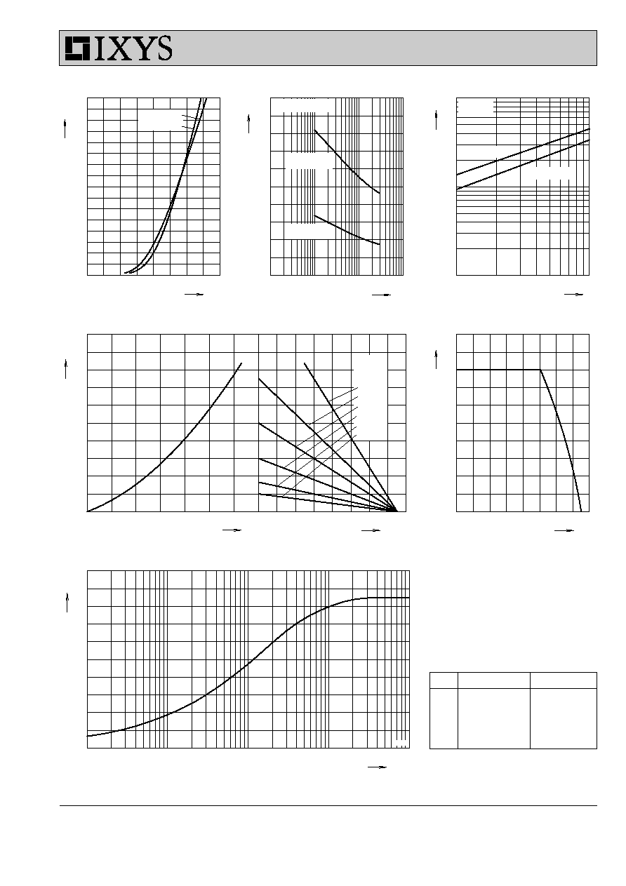
Fig. 1 Forward current versus voltage
drop per diode
Fig. 2 Surge overload current
Fig. 3 I
2
t versus time per diode
Fig. 4 Power dissipation versus direct output current and ambient temperature
Fig. 5 Max. forward current versus case
temperature
Fig. 6 Transient thermal impedance junction to case
R
thHA
:
0.1 K/W
0.5 K/W
1.0 K/W
2.0 K/W
4.0 K/W
7.0 K/W
T
VJ
= 150∞C
T
VJ
= 45∞C
T
VJ
=125∞C
T
VJ
= 25∞C
T
VJ
= 150∞C
Z
thJC
Constants for Z
thJC
calculation:
i
R
thi
(K/W)
t
i
(s)
1
0.081
0.00024
2
0.1449
0.0036
3
0.2982
0.0235
4
0.735
0.142
5
0.441
0.7
VBO 40