
JIANGSU CHANGJIANG ELECTRONICS TECHNOLOGY CO., LTD
Digital transistors (built-in resistors)
DTC114TE/DTC114TUA
DTC114TKA/DTC114TCA /DTC114TSA
DIGITAL TRANSISTOR (NPN)
FEATURES
Built-in bias resistors enable the configuration of an
inverter circuit without connecting extemal input resistors.
The bias resistors conisit of thin-film resistors with
complete isolation to without connecting extemal input.
They also have the advantage of almost completely
Eliminating parasitic effects.
Only the on/off conditions need to be set for operation,
marking device design easy.
PIN CONNENCTIONS AND MARKING
(1) Emitter
(2) Collector
(3) Base
(1) Base
(2) Emitter
(3) Collector
(1) Base
(2) Emitter
(3) Collector
(1) Base
(2) Emitter
(3) Collector
(1) Base
(2) Emitter
(3) Collector
(1) Base
(2) Emitter
(3) Collector
(1) Base
(2) Emitter
(3) Collector
(1) Base
(2) Emitter
(3) Collector
Addreviated symbol:
04
SOT-523
Addreviated symbol:
04
SOT-23-3L
SOT-23
SOT-323
TO-92S
DTC114TE
DTC114TUA
DTA114ECA
DTC114TCA
DTC114TKA
DTC114TSA
Addreviated symbol:
04
Addreviated symbol:
04
MAXIMUM RATINGS* T
A
=25
unless otherwise noted
LIMITS(DTC114T
)
Symbol Parameter
E UA KA CA
SA
Units
V
CBO
Collector-Base Voltage
50 V
V
CEO
Collector-Emitter Voltage
50 V
V
EBO
Emitter-Base Voltage
5
V
I
C
Collector Current -Continuous
100
mA
P
C
Collector Dissipation
150
200
300
mW
Tj
Junction temperature
150
T
J
, T
stg
Junction and Storage Temperature
-55~+150
ELECTRICAL CHARACTERISTICS (Tamb=25
unless otherwise specified)
Parameter
Symbol
Test conditions
MIN
TYP
MAX
UNIT
Collector-base breakdown voltage
V
(BR)CBO
Ic=
50�
A,I
E
=0
50 V
Collector-emitter breakdown voltage
V
(BR)CEO
Ic=
1
mA,I
B
=0
50 V
Emitter-base breakdown voltage
V
(BR)EBO
I
E
=
50�
A,I
C
=0
5 V
Collector cut-off current
I
CBO
V
CB
=
50
V,I
E
=0
0.5
uA
Emitter cut-off current
I
EBO
V
EB
=
4
V,I
C
=0
0.5
uA
DC current gain
h
FE
V
CE
=
5
V,I
C
=
1
mA
100 300 600
Collector-emitter saturation voltage
V
CE(sat)
I
C
=10mA,I
B
=1mA
0.3
V
Transition frequency
f
T
V
CE
=
10
V,I
E
=-
5
mA, f=
100
MHz
250 MHz
Imput resistor
R1
7
10
13
k
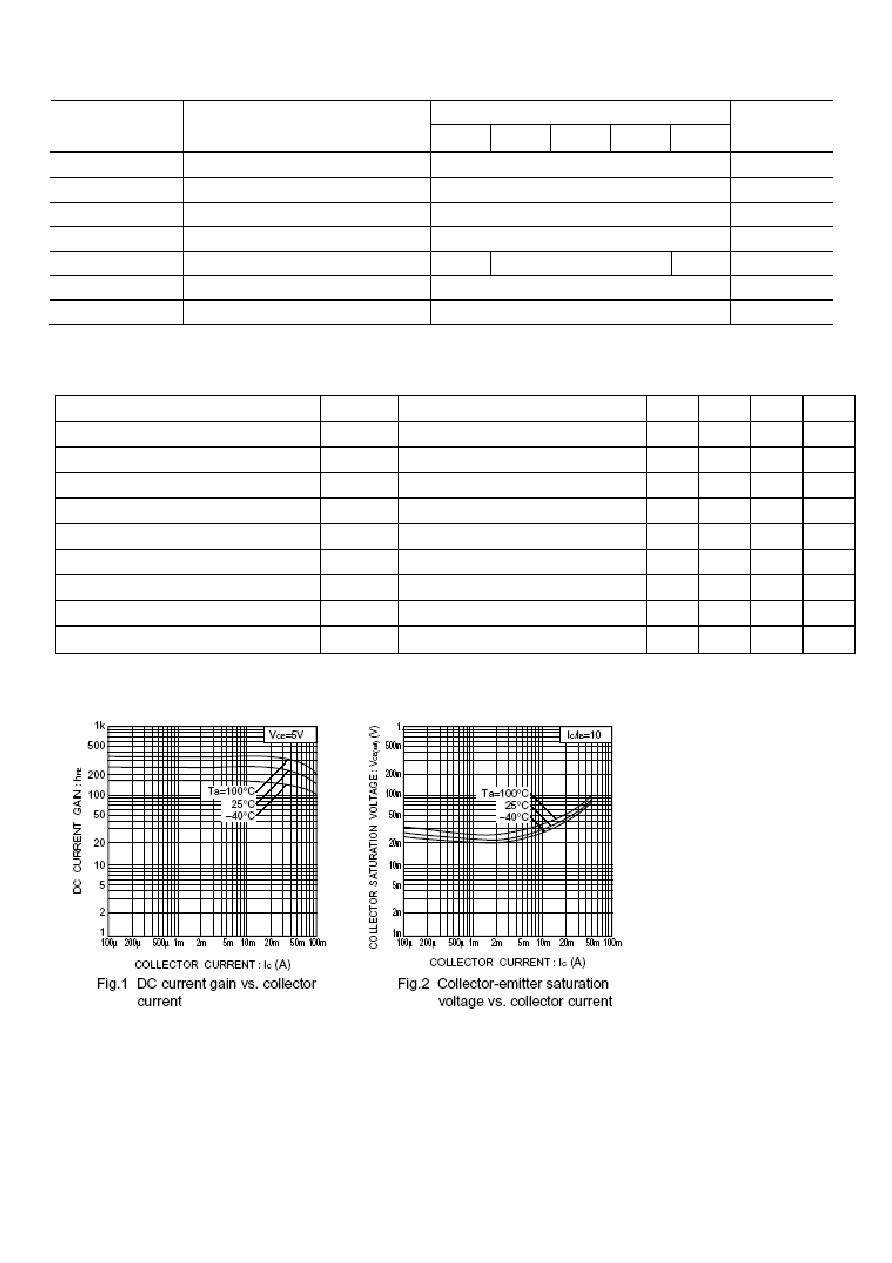
Typical Characteristics