Document Outline
- Ceramic Leaded Capacitors
- Index
- Multilayer Ceramic Capacitors/Axial & Radial
- Conformally Coated/Axial & Radial
- Performance Characteristics
- General Specifications
- Electrical
- Environmental
- "Aximax" Conformally Coated Axial
- Outline Drawing
- Dimensions
- Ordering Information
- Marking
- Part Number Reference
- "Golden Max" Conformally Coated Radial
- Outline Drawings
- Dimensions
- Ordering Information
- Marking
- Part Number Reference
- Optional Lead Configurations
- Ceramic Molded/Axial & Radial
- Performance Characteristics
- General Specifications
- Electrical
- Environmental
- Ceramic Molded Standard/Axial & Radial
- Outline Drawing
- Dimensions
- Ordering Information
- Marking
- Part Number Reference
- Mil-PRF-20
- Outline Drawings
- Dimensions
- Ordering Information
- Marking
- Part Number Reference
- Mil-C-11015 (CK) & Mil-PRF-39014 (CKR)
- Outline Drawings
- Dimensions
- Ordering Information
- Marking
- Part Number Reference
- Ceramic Axial Tape & Reel Packaging Specifications
- Ceramic Radial Tape & Reel Packaging Specifications
- Ceramic Leaded Packaging Quantities
- Application Notes for Multilayer Ceramic Capacitors
- KEMET Home Page
- KnowledgeEdge - Technical Help
- Submit Feedback
- Find a KEMET Distributor
- Catalogs and Datasheets
C
ERAMIC
L
EADED
C
APACITORS
To find parts fast, visit CapacitorEdge
sm
at www.kemet.com.
F-3101D 7/00
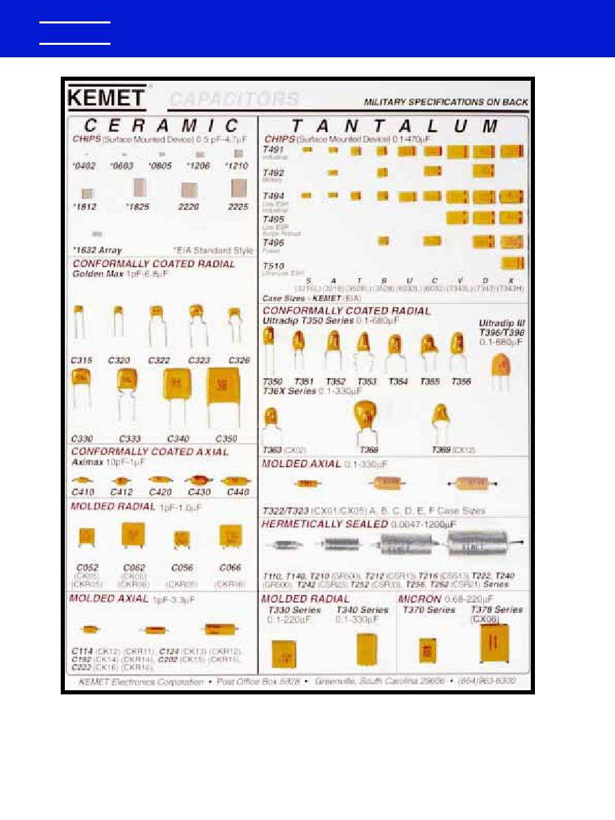
CAPACITORS
GR900 and MIL-PRF-123 High-Reliability Ceramic Capacitors are available.
Refer to catalog F-3054 for detailed information. KEMET also manufactures
Tantalum Leaded, and Surface Mount Capacitors -- Tantalum and Ceramic.
Refer to catalog F-3100 -- Tantalum Leaded, and F3102 -- Surface Mount
for detailed information on these products.
KEMET
�
0988 Layout rev 8/9/2000 9:54 AM Page 2

KEMET Electronics Corporation, P.O. Box 5928, Greenville, S.C. 29606, (864) 963-6300
3
KEMET
�
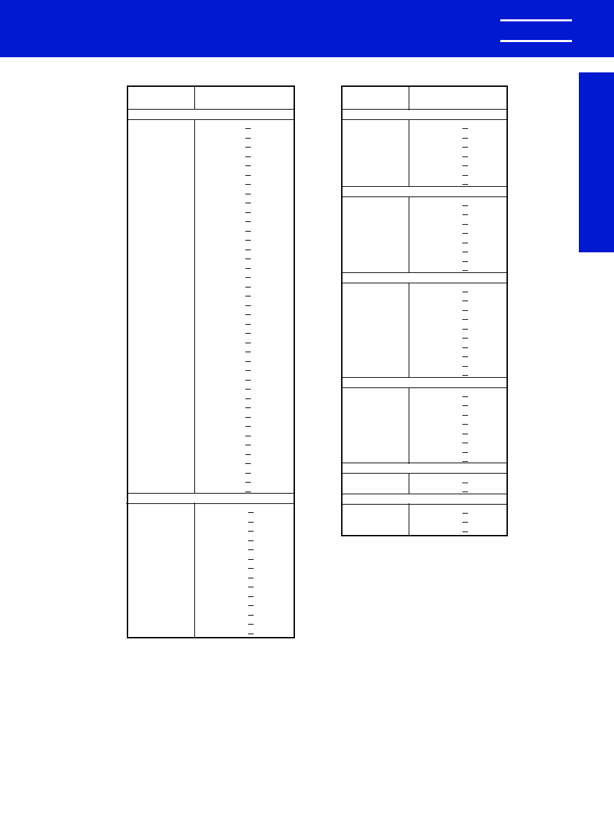
INDEX
Multilayer Ceramic Capacitors/Axial & Radial
Page
General Information . . . . . . . . . . . . . . . . . . . . . . . . . . . . . . . . . . . . . . . . . . . . . . . . . . . . . . . . . . . . . . . . . . . . . . . . . . . .4
Conformally Coated/Axial & Radial
Performance Characteristics
General Specifications . . . . . . . . . . . . . . . . . . . . . . . . . . . . . . . . . . . . . . . . . . . . . . . . . . . . . . . . . . . . . . . . . . . . . .5
Electrical . . . . . . . . . . . . . . . . . . . . . . . . . . . . . . . . . . . . . . . . . . . . . . . . . . . . . . . . . . . . . . . . . . . . . . . . . . . . . . . . .5
Environmental . . . . . . . . . . . . . . . . . . . . . . . . . . . . . . . . . . . . . . . . . . . . . . . . . . . . . . . . . . . . . . . . . . . . . . . . . . . . .5
"Aximax" Conformally Coated Axial
Outline Drawing . . . . . . . . . . . . . . . . . . . . . . . . . . . . . . . . . . . . . . . . . . . . . . . . . . . . . . . . . . . . . . . . . . . . . . . . . . .6
Dimensions . . . . . . . . . . . . . . . . . . . . . . . . . . . . . . . . . . . . . . . . . . . . . . . . . . . . . . . . . . . . . . . . . . . . . . . . . . . . . . .6
Ordering Information . . . . . . . . . . . . . . . . . . . . . . . . . . . . . . . . . . . . . . . . . . . . . . . . . . . . . . . . . . . . . . . . . . . . . . . .6
Marking . . . . . . . . . . . . . . . . . . . . . . . . . . . . . . . . . . . . . . . . . . . . . . . . . . . . . . . . . . . . . . . . . . . . . . . . . . . . . . . . .6
Part Number Reference . . . . . . . . . . . . . . . . . . . . . . . . . . . . . . . . . . . . . . . . . . . . . . . . . . . . . . . . . . . . . . . . . . . . . .7
"Golden Max" Conformally Coated Radial
Outline Drawings . . . . . . . . . . . . . . . . . . . . . . . . . . . . . . . . . . . . . . . . . . . . . . . . . . . . . . . . . . . . . . . . . . . . . . . . . . .8
Dimensions . . . . . . . . . . . . . . . . . . . . . . . . . . . . . . . . . . . . . . . . . . . . . . . . . . . . . . . . . . . . . . . . . . . . . . . . . . . . . . .8
Ordering Information . . . . . . . . . . . . . . . . . . . . . . . . . . . . . . . . . . . . . . . . . . . . . . . . . . . . . . . . . . . . . . . . . . . . . . . .8
Marking . . . . . . . . . . . . . . . . . . . . . . . . . . . . . . . . . . . . . . . . . . . . . . . . . . . . . . . . . . . . . . . . . . . . . . . . . . . . . . . . .9
Part Number Reference . . . . . . . . . . . . . . . . . . . . . . . . . . . . . . . . . . . . . . . . . . . . . . . . . . . . . . . . . . . . . . . . . .9 - 11
Optional Lead Configurations . . . . . . . . . . . . . . . . . . . . . . . . . . . . . . . . . . . . . . . . . . . . . . . . . . . . . . . . . . . . . . . .12
Ceramic Molded/Axial & Radial
Performance Characteristics
General Specifications . . . . . . . . . . . . . . . . . . . . . . . . . . . . . . . . . . . . . . . . . . . . . . . . . . . . . . . . . . . . . . . . . . . . .13
Electrical . . . . . . . . . . . . . . . . . . . . . . . . . . . . . . . . . . . . . . . . . . . . . . . . . . . . . . . . . . . . . . . . . . . . . . . . . . . . . . . .13
Environmental . . . . . . . . . . . . . . . . . . . . . . . . . . . . . . . . . . . . . . . . . . . . . . . . . . . . . . . . . . . . . . . . . . . . . . . . . . . .13
Ceramic Molded Standard/Axial & Radial
Outline Drawing . . . . . . . . . . . . . . . . . . . . . . . . . . . . . . . . . . . . . . . . . . . . . . . . . . . . . . . . . . . . . . . . . . . . . . . . . .14
Dimensions . . . . . . . . . . . . . . . . . . . . . . . . . . . . . . . . . . . . . . . . . . . . . . . . . . . . . . . . . . . . . . . . . . . . . . . . . . . . . .14
Ordering Information . . . . . . . . . . . . . . . . . . . . . . . . . . . . . . . . . . . . . . . . . . . . . . . . . . . . . . . . . . . . . . . . . . . . . . .15
Marking . . . . . . . . . . . . . . . . . . . . . . . . . . . . . . . . . . . . . . . . . . . . . . . . . . . . . . . . . . . . . . . . . . . . . . . . . . . . . . . . .15
Part Number Reference . . . . . . . . . . . . . . . . . . . . . . . . . . . . . . . . . . . . . . . . . . . . . . . . . . . . . . . . . . . . . . . . .16 - 19
Mil-PRF-20
Outline Drawings . . . . . . . . . . . . . . . . . . . . . . . . . . . . . . . . . . . . . . . . . . . . . . . . . . . . . . . . . . . . . . . . . . . . . . . . . .20
Dimensions . . . . . . . . . . . . . . . . . . . . . . . . . . . . . . . . . . . . . . . . . . . . . . . . . . . . . . . . . . . . . . . . . . . . . . . . . . . . . .20
Ordering Information . . . . . . . . . . . . . . . . . . . . . . . . . . . . . . . . . . . . . . . . . . . . . . . . . . . . . . . . . . . . . . . . . . . . . . .21
Marking . . . . . . . . . . . . . . . . . . . . . . . . . . . . . . . . . . . . . . . . . . . . . . . . . . . . . . . . . . . . . . . . . . . . . . . . . . . . . . . . .21
Part Number Reference . . . . . . . . . . . . . . . . . . . . . . . . . . . . . . . . . . . . . . . . . . . . . . . . . . . . . . . . . . . . . . . . .22 - 25
Mil-C-11015 (CK) & Mil-PRF-39014 (CKR)
Outline Drawings . . . . . . . . . . . . . . . . . . . . . . . . . . . . . . . . . . . . . . . . . . . . . . . . . . . . . . . . . . . . . . . . . . . . . . . . . .26
Dimensions . . . . . . . . . . . . . . . . . . . . . . . . . . . . . . . . . . . . . . . . . . . . . . . . . . . . . . . . . . . . . . . . . . . . . . . . . . . . . .26
Ordering Information . . . . . . . . . . . . . . . . . . . . . . . . . . . . . . . . . . . . . . . . . . . . . . . . . . . . . . . . . . . . . . . . . . . . . . .27
Marking . . . . . . . . . . . . . . . . . . . . . . . . . . . . . . . . . . . . . . . . . . . . . . . . . . . . . . . . . . . . . . . . . . . . . . . . . . . . . . . . .27
Part Number Reference . . . . . . . . . . . . . . . . . . . . . . . . . . . . . . . . . . . . . . . . . . . . . . . . . . . . . . . . . . . . . . . . .28 - 31
Ceramic Axial Tape & Reel Packaging Specifications
. . . . . . . . . . . . . . . . . . . . . . . . . . . . . . . . .32
Ceramic Radial Tape & Reel Packaging Specifications
. . . . . . . . . . . . . . . . . . . . . . . . . . . . . . .33
Ceramic Leaded Packaging Quantities
. . . . . . . . . . . . . . . . . . . . . . . . . . . . . . . . . . . . . . . . . . . . . . . .34
Application Notes for Multilayer Ceramic Capacitors
. . . . . . . . . . . . . . . . . . . . . . . . . . . . .35 - 39
NOTICE
Although the information in this catalog has been carefully
checked for accuracy, and is believed to be correct and
current, no warranty, either express or implied, is made as to
either its applicability to, or its compatibility with, specific
requirements; nor does KEMET Electronics Corporation
assume any responsibility for correctness of this
information, nor for damages consequent to its use. All
design characteristics, specifications, tolerances, and the
like are subject to change without notice.
0988 Layout rev 8/9/2000 9:54 AM Page 3
MULTILAYER CERAMIC CAPACITORS/AXIAL & RADIAL LEADED
KEMET Electronics Corporation, P.O. Box 5928, Greenville, S.C. 29606, (864) 963-6300
4
KEMET
�
Multilayer ceramic capacitors are available in a
variety of physical sizes and configurations, including
leaded devices and surface mounted chips. Leaded
styles include molded and conformally coated parts
with axial and radial leads. However, the basic
capacitor element is similar for all styles. It is called a
chip and consists of formulated dielectric materials
which have been cast into thin layers, interspersed
with metal electrodes alternately exposed on opposite
edges of the laminated structure. The entire structure is
fired at high temperature to produce a monolithic
block which provides high capacitance values in a
small physical volume. After firing, conductive
terminations are applied to opposite ends of the chip to
make contact with the exposed electrodes.
Termination materials and methods vary depending on
the intended use.
TEMPERATURE CHARACTERISTICS
Ceramic dielectric materials can be formulated with
a wide range of characteristics. The EIA standard for
ceramic dielectric capacitors (RS-198) divides ceramic
dielectrics into the following classes:
Class I: Temperature compensating capacitors,
suitable for resonant circuit application or other appli-
cations where high Q and stability of capacitance char-
acteristics are required. Class I capacitors have
predictable temperature coefficients and are not
affected by voltage, frequency or time. They are made
from materials which are not ferro-electric, yielding
superior stability but low volumetric efficiency. Class I
capacitors are the most stable type available, but have
the lowest volumetric efficiency.
Class II: Stable capacitors, suitable for bypass
or coupling applications or frequency discriminating
circuits where Q and stability of capacitance char-
acteristics are not of a major importance. Class II
capacitors have temperature characteristics of � 15%
or less. They are made from materials which are
ferro-electric, yielding higher volumetric efficiency but
less stability. Class II capacitors are affected by
temperature, voltage, frequency and time.
Class III: General purpose capacitors, suitable
for by-pass coupling or other applications in which
dielectric losses, high insulation resistance and
stability of capacitance characteristics are of little or
no importance. Class III capacitors are similar to Class
II capacitors except for temperature characteristics,
which are greater than � 15%. Class III capacitors
have the highest volumetric efficiency and poorest
stability of any type.
KEMET leaded ceramic capacitors are offered in
the three most popular temperature characteristics:
C0G: Class I, with a temperature coefficient of 0 �
30 ppm per degree C over an operating
temperature range of - 55�C to + 125�C (Also
known as "NP0").
X7R: Class II, with a maximum capacitance
change of � 15% over an operating temperature
range of - 55�C to + 125�C.
Z5U: Class III, with a maximum capacitance
change of + 22% - 56% over an operating tem-
perature range of + 10�C to + 85�C.
Specified electrical limits for these three temperature
characteristics are shown in Table 1.
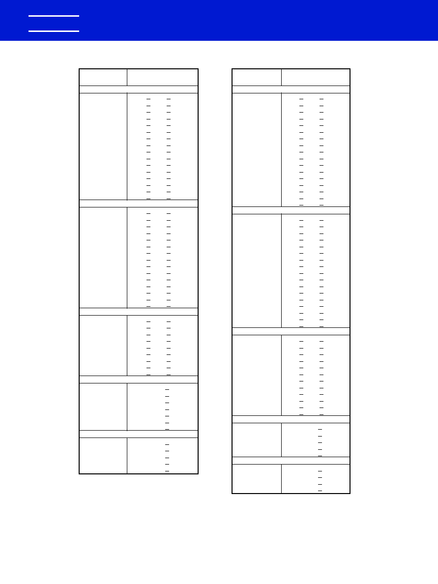
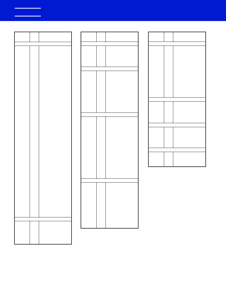
SPECIFIED ELECTRICAL LIMITS
TEMPERATURE CHARACTERISTICS
PARAMETER
C0G
X7R
Z5U
Dissipation Factor: Measured at following conditions:
C0G -- 1 kHz and 1 vrms if capacitance > 1000 pF
1 MHz and 1 vrms if capacitance
1000 pF
0.15%
2.5%
4.0%
X7R -- 1 kHz and 1 vrms*
Z5U -- 1 kHz and 0.5 vrms
Dielectric Strength: 2.5 times rated DC voltage.
Pass Subsequent IR Test
Insulation Resistance (IR): At rated DC voltage,
1,000 M
-�F
1,000 M
-�F
1,000 M
-�F
whichever of the two is smaller
or 100 G
or 100 G
or 10 G
Temperature Characteristics: Range, �C
-55 to 125
-55 to 125
+10 to 85
Capacitance Change without
0 � 30 ppm/�C
�15%
+22%, -56%
DC voltage
* 1 MHz and 1 vrms if capacitance
100 pF on military product.
Table I
0988 Layout rev 8/9/2000 9:54 AM Page 4

KEMET Electronics Corporation, P.O. Box 5928, Greenville, S.C. 29606, (864) 963-6300
5
KEMET
�
CERAMIC CONFORMALLY COATED/AXIAL & RADIAL
PERFORMANCE CHARACTERISTICS
GENERAL SPECIFICATIONS
Working Voltage:
Axial
Radial
C0G
50 & 100 volts
100 & 200 volts
X7R
50 & 100 volts
50, 100 & 200 volts
Z5U
50 & 100 volts
50 & 100 volts
Temperature Characteristics:
C0G
0 � 30 PPM/�C from - 55�C to + 125�C
(1)
X7R
� 15% from - 55�C to + 125�C
Z5U
+ 22%; - 56% from + 10�C to + 85�C
Capacitance Tolerance:
C0G
� 5%, � 10%, � 20%
X7R
� 10%, � 20%
Z5U
� 20%, - 20 + 80%, - 0 + 100%
Construction:
Epoxy encapsulated - meets flame test require-
ments of UL Standard 94V-0.
High-temperature solder - meets EIA RS-198D,
Method 302, Condition B (260�C for 10 sec.)
Lead Material:
Solder Coated Copper Clad Steel
Solderability:
EIA RS-198D, Method 302, Solder temperature -
230� � 5�C. Dwell time in solder - 7 � 1/2 seconds.
Terminal Strength:
EIA RS-198D, Method 303, Condition A (2.2 kg)
ELECTRICAL @ 25�C
Capacitance:
Within specified tolerance at 25�C and following
test conditions.
C0G - Greater than 1000 pF with 1.0 vrms at 1 kHz.
- 1000 pF and less with 1.0 vrms at 1 MHz.
X7R - with 1.0 vrms at 1 kHz.
Z5U - with 0.5 vrms at 1 kHz.
Dissipation Factor:
At 25�C - same test conditions as capacitance.
C0G - 0.15% maximum
X7R - 2.5% maximum
Z5U - 4.0% maximum
Insulation Resistance:
EIA RS-198D, Method 104, Condition A
C0G - 100 gigohms or 1000 megohm x �F,
whichever is less.
X7R -100 gigohms or 1000 megohm x �F,
whichever is less.
Z5U -10 gigohms or 1000 megohm x �F,
whichever is less.
Dielectric Withstanding Voltage:
EIA RS-198D, Method 103 (250% of rated voltage
for 5 seconds, with current limited to 50mA)
ENVIRONMENTAL
Vibration:
EIA RS-198D, Method 304, Condition D (10-2000
Hz; 20g)
Shock:
EIA RS-198D, Method 305, Condition I (100g)
Life Test:
EIA RS-198D, Method 201, Condition D. Test
Potential and Temperature.
C0G- 200% of rated voltage at + 125�C
X7R - 200% of rated voltage at + 125�C
Z5U - 200% of rated voltage at + 85�C
Post-Test Limits at + 25�C are:
Capacitance Change:
C0G - � 3%, or 0.25 pF, whichever is greater.
X7R - � 20% of initial value.
(2)
Z5U - � 30% of initial value.
(2)
Dissipation Factor:
C0G - 0.25% maximum
X7R - 3.0% maximum
Z5U - 4.0% maximum
Insulation Resistance:
C0G - 10 gigohms or 100 megohm x �F,
whichever is less.
X7R - 10 gigohms or 100 megohm x �F,
whichever is less.
Z5U - 1 gigohm or 100 megohm x �F,
whichever is less.
Moisture Resistance:
EIA RS-198D, Method 204, Condition A (10 cycles
without applied voltage.
Post-Test Limits at + 25�C are:
Capacitance Change:
C0G - 3%, or 0.25 pF, whichever is greater.
X7R - � 20% of initial value.
(2)
Z5U - � 30% of initial value.
(2)
Dissipation Factor:
C0G - 0.25% maximum
X7R - 3.0% maximum
Z5U - 4.0% maximum
Insulation Resistance:
C0G - 10 gigohms or 100 megohm x �F,
whichever is less.
X7R - 10 gigohms or 100 megohm x �F,
whichever is less.
Z5U - 1 gigohm or 100 megohm x �F,
whichever is less.
Thermal Shock:
EIA RS-198D, Method 202, Condition B (C0G &
X7R: - 55�C to + 125�C; Z5U: - 55�C to + 85�C)
(1)
+53 ppm -30 ppm/�C from + 25�C to - 55�C, � 60
ppm below 10 pF.
(2)
X7R & Z5U dielectrics exhibit aging characteristics;
therefore, it is highly recommended that capacitors
be deaged for 2 hours at 150�C and stabilized at
room temperature for 48 hours before capacitance
measurements are made.
Conformally Coated
Axial/Radial
0988 Layout rev 8/9/2000 9:54 AM Page 5

CERAMIC CONFORMALLY COATED/AXIAL
"AXIMAX"
KEMET Electronics Corporation, P.O. Box 5928, Greenville, S.C. 29606, (864) 963-6300
6
KEMET
�
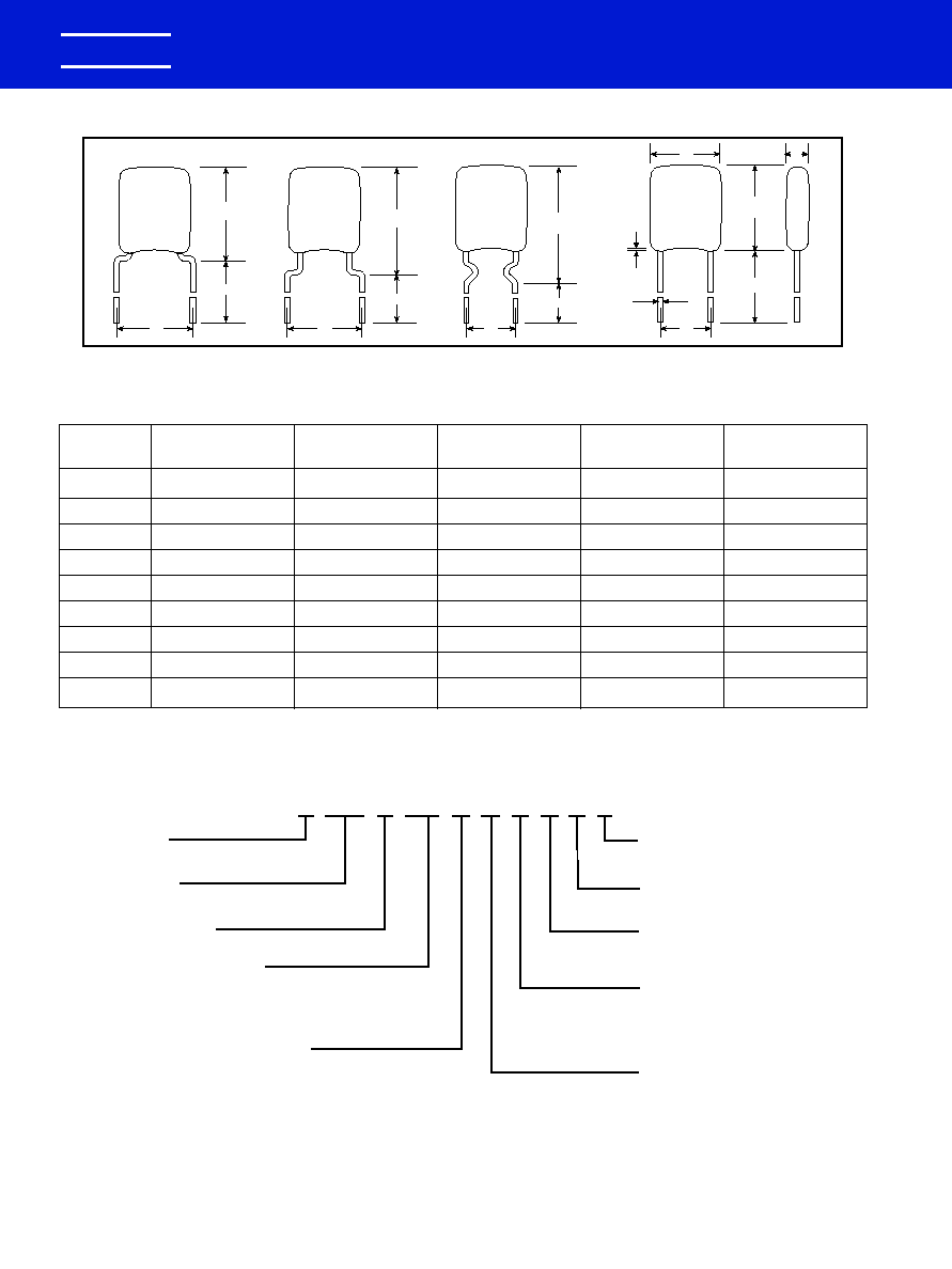
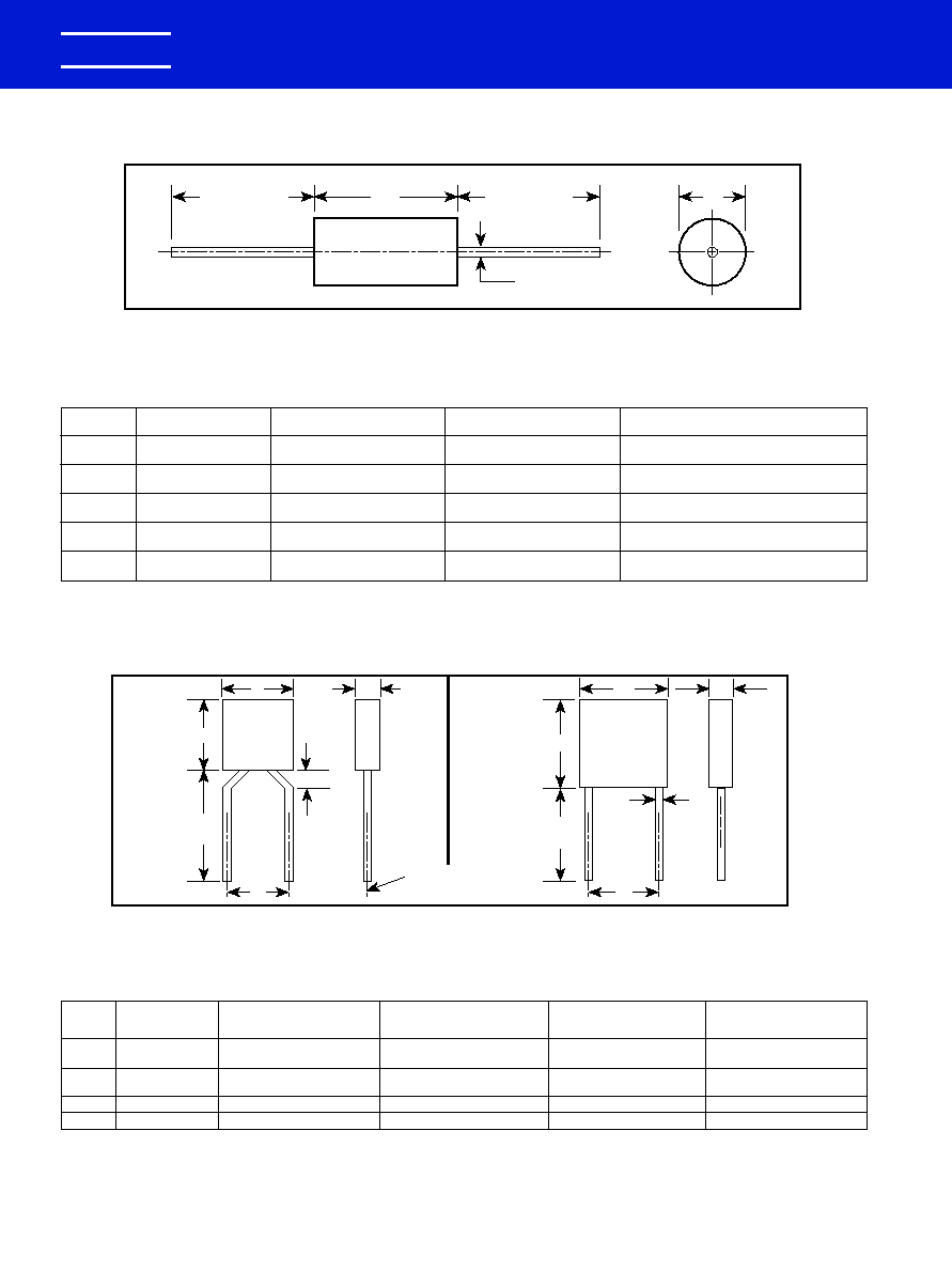
CAPACITANCE OUTLINE DRAWING
MAXIMUM DIMENSIONS--INCHES & (MILLIMETERS)
ORDERING INFORMATION
MARKING INFORMATION
LD
STYLE
L
D
LL
MAX
MAX
MIN
C410
.170 (4.32)
.100 (2.54)
.020 (.51)
1.0 (25.4)
C412
.170 (4.32)
.120 (3.05)
.020 (.51)
1.0 (25.4)
C420
.260 (6.60)
.100 (2.54)
.020 (.51)
1.0 (25.4)
C430
.290 (7.37)
.150 (3.81)
.020 (.51)
1.0 (25.4)
C440
.400 (10.16)
.150 (3.81)
.020 (.51)
1.0 (25.4)
+.001, -.003
(+.025, -.076)
M
104
410
C
5
C
A
U
5
C
CERAMIC
CASE SIZE
(See Table of Dimensions above)
SPECIFICATION
C -- Standard
CAPACITANCE
Expressed in Picofarad Code (pF)
First Two Digits -- Significant Figures
Third Digit -- Number of Zeros
FAILURE RATE
INTERNAL CONSTRUCTION
CAPACITANCE TOLERANCE
J --
�
5%
K --
�
10%
M --
�
20%
Z -- �20 +80%
A -- Not Applicable
LEAD MATERIAL
C -- Standard
5 -- Standard
DIELECTRIC
EIA Designation
G -- C0G (NPO) -- Ultra-Stable
R -- X7R -- Stable
U -- Z5U -- General Purpose
RATED VOLTAGE
1 -- 100 Volts
5 -- 50 Volts
*
*Part Number Example: C410C104M5U5CA (14 digits � no spaces)
LL
L
D
LD
K5R
104K
AB
0037
Manufacturer
(KEMET)
Rated Voltage
5 - 50 volts
1 - 100 volts
Dielectric
G � C0G/NP0
R � X7R
U � Z5U
Capacitance
Tolerance
Capacitance
Code
Lot
Code
Date
Code
0988 Layout rev 8/9/2000 9:54 AM Page 6
CAPACITANCE
KEMET
pF
PART NUMBER
100 VOLT - Z5U
10,000
C410C103(1)1U5CA
12,000
C410C123(1)1U5CA
15,000
C410C153(1)1U5CA
18,000
C410C183(1)1U5CA
22,000
C410C223(1)1U5CA
27,000
C420C273(1)1U5CA
33,000
C420C333(1)1U5CA
39,000
C420C393(1)1U5CA
47,000
C420C473(1)1U5CA
56,000
C430C563(1)1U5CA
68,000
C430C683(1)1U5CA
82,000
C430C823(1)1U5CA
100,000
C430C104(1)1U5CA
120,000
C430C124(1)1U5CA
150,000
C430C154(1)1U5CA
180,000
C440C184(1)1U5CA
220,000
C440C224(1)1U5CA
50 VOLT - Z5U
27,000
C410C273(1)5U5CA
33,000
C410C333(1)5U5CA
39,000
C410C393(1)5U5CA
47,000
C410C473(1)5U5CA
56,000
C410C563(1)5U5CA
68,000
C410C683(1)5U5CA
82,000
C410C823(1)5U5CA
100,000
C410C104(1)5U5CA
120,000
C410C124(1)5U5CA
150,000
C410C154(1)5U5CA
180,000
C410C184(1)5U5CA
220,000
C410C224(1)5U5CA
270,000
C412C274(1)5U5CA
330,000
C412C334(1)5U5CA
270,000
C420C274(1)5U5CA
330,000
C420C334(1)5U5CA
390,000
C430C394(1)5U5CA
470,000
C430C474(1)5U5CA
560,000
C430C564(1)5U5CA
680,000
C430C684(1)5U5CA
820,000
C440C824(1)5U5CA
1,000,000
C440C105(1)5U5CA
KEMET Electronics Corporation, P.O. Box 5928, Greenville, S.C. 29606, (864) 963-6300
7
KEMET
�
CERAMIC CONFORMALLY COATED/AXIAL
"AXIMAX"
AXIMAX
RATINGS & PART NUMBER REFERENCE
CAPACITANCE
KEMET
pF
PART NUMBER
100 VOLT - C0G
10
C410C100(1)1G5CA
12
C410C120(1)1G5CA
15
C410C150(1)1G5CA
18
C410C180(1)1G5CA
22
C410C220(1)1G5CA
27
C410C270(1)1G5CA
33
C410C330(1)1G5CA
39
C410C390(1)1G5CA
47
C410C470(1)1G5CA
56
C410C560(1)1G5CA
68
C410C680(1)1G5CA
82
C410C820(1)1G5CA
100
C410C101(1)1G5CA
120
C410C121(1)1G5CA
150
C410C151(1)1G5CA
180
C410C181(1)1G5CA
220
C410C221(1)1G5CA
270
C410C271(1)1G5CA
330
C410C331(1)1G5CA
390
C410C391(1)1G5CA
470
C410C471(1)1G5CA
560
C410C561(1)1G5CA
680
C410C681(1)1G5CA
820
C410C821(1)1G5CA
1,000
C410C102(1)1G5CA
1,200
C420C122(1)1G5CA
1,500
C420C152(1)1G5CA
1,800
C420C182(1)1G5CA
2,200
C420C222(1)1G5CA
2,700
C430C272(1)1G5CA
3,300
C430C332(1)1G5CA
3,900
C430C392(1)1G5CA
4,700
C430C472(1)1G5CA
5,600
C430C562(1)1G5CA
6,800
C430C682(1)1G5CA
8,200
C430C822(1)1G5CA
10,000
C440C103(1)1G5CA
12,000
C440C123(1)1G5CA
15,000
C440C153(1)1G5CA
50 VOLT - C0G
560
C410C561(1)5G5CA
680
C410C681(1)5G5CA
820
C410C821(1)5G5CA
1,000
C410C102(1)5G5CA
1,200
C412C122(1)5G5CA
1,500
C412C152(1)5G5CA
1,800
C412C182(1)5G5CA
2,200
C412C222(1)5G5CA
2,700
C412C272(1)5G5CA
1,200
C420C122(1)5G5CA
1,500
C420C152(1)5G5CA
1,800
C420C182(1)5G5CA
2,200
C420C222(1)5G5CA
2,700
C430C272(1)5G5CA
3,300
C430C332(1)5G5CA
3,900
C430C392(1)5G5CA
4,700
C430C472(1)5G5CA
5,600
C430C562(1)5G5CA
6,800
C430C682(1)5G5CA
8,200
C430C822(1)5G5CA
10,000
C440C103(1)5G5CA
12,000
C440C123(1)5G5CA
15,000
C440C153(1)5G5CA
ULTRA-STABLE
TEMPERATURE
CHARACTERISTIC--C0G/NP0
CAPACITANCE
KEMET
pF
PART NUMBER
100 VOLT - X7R
470
C410C471(1)1R5CA
560
C410C561(1)1R5CA
680
C410C681(1)1R5CA
820
C410C821(1)1R5CA
1,000
C410C102(1)1R5CA
1,200
C410C122(1)1R5CA
1,500
C410C152(1)1R5CA
1,800
C410C182(1)1R5CA
2,200
C410C222(1)1R5CA
2,700
C410C272(1)1R5CA
3,300
C410C332(1)1R5CA
3,900
C410C392(1)1R5CA
4,700
C410C472(1)1R5CA
5,600
C410C562(1)1R5CA
6,800
C410C682(1)1R5CA
8,200
C410C822(1)1R5CA
10,000
C410C103(1)1R5CA
12,000
C410C123(1)1R5CA
15,000
C412C153(1)1R5CA
18,000
C412C183(1)1R5CA
22,000
C412C223(1)1R5CA
27,000
C412C273(1)1R5CA
15,000
C420C153(1)1R5CA
18,000
C420C183(1)1R5CA
22,000
C420C223(1)1R5CA
27,000
C420C273(1)1R5CA
33,000
C420C333(1)1R5CA
39,000
C430C393(1)1R5CA
47,000
C430C473(1)1R5CA
56,000
C430C563(1)1R5CA
68,000
C430C683(1)1R5CA
82,000
C430C823(1)1R5CA
100,000
C430C104(1)1R5CA
120,000
C440C124(1)1R5CA
150,000
C440C154(1)1R5CA
50 VOLT - X7R
8,200
C410C822(1)5R5CA
10,000
C410C103(1)5R5CA
12,000
C410C123(1)5R5CA
15,000
C410C153(1)5R5CA
18,000
C410C183(1)5R5CA
22,000
C410C223(1)5R5CA
27,000
C410C273(1)5R5CA
33,000
C410C333(1)5R5CA
39,000
C410C393(1)5R5CA
47,000
C410C473(1)5R5CA
56,000
C412C563(1)5R5CA
68,000
C412C683(1)5R5CA
82,000
C412C823(1)5R5CA
100,000
C412C104(1)5R5CA
56,000
C420C563(1)5R5CA
68,000
C420C683(1)5R5CA
82,000
C420C823(1)5R5CA
100,000
C420C104(1)5R5CA
120,000
C430C124(1)5R5CA
150,000
C430C154(1)5R5CA
180,000
C430C184(1)5R5CA
220,000
C430C224(1)5R5CA
270,000
C430C274(1)5R5CA
330,000
C440C334(1)5R5CA
390,000
C440C394(1)5R5CA
470,000
C440C474(1)5R5CA
SINGLE
TEMPERATURE
CHARACTERISTIC--X7R
(1) Insert proper letter for capacitance tolerance desired:
J = �5%
K = �10%
M = �20%
(1) Insert proper letter for capacitance tolerance desired:
K = �10%, M = �20%
GENERAL PURPOSE
TEMPERATURE
CHARACTERISTIC--Z5U
(1) Insert proper letter for capacitance tolerance desired:
M = �20%, Z = +80, -20%
For packaging information, see pages 32 and 34.
0988 Layout rev 8/9/2000 9:54 AM Page 7
CERAMIC CONFORMALLY COATED/RADIAL
"GOLDEN MAX"
KEMET Electronics Corporation, P.O. Box 5928, Greenville, S.C. 29606, (864) 963-6300
8
KEMET
�
S
C315
C320
C330
C340
C350
H
*
C333
H
*.276 (7.00) MIN.
S
C323
H
*
S
H
*
C317
C322
S
D
.060
(1.52)
MAX.
L
T
*
DIMENSIONS -- INCHES & MILLIMETERS
CASE
L
H
T
S(1)
D
SIZE
MAX.
MAX.
MAX.
�.030
+.004 - .001
C315
.150 (3.81)
.210 (5.33)
.100 (2.54)
.100 (2.54)
.020 (.51)
C317
.150 (3.81)
.230 (5.84)
.100 (2.54)
.200 (5.08)
.020 (.51)
C320
.200 (5.08)
.260 (6.60)
.125 (3.18)
.100 (2.54)
.020 (.51)
C322
.200 (5.08)
.260 (6.60)
.125 (3.18)
.200 (5.08)
.020 (.51)
C323
.200 (5.08)
.320 (8.13)
.125 (3.18)
.200 (5.08)
.020 (.51)
C330
.300 (7.62)
.360 (9.14)
.150 (3.81)
.200 (5.08)
.020 (.51)
C333
.300 (7.62)
.390 (9.91)
.150 (3.81)
.200 (5.08)
.020 (.51)
C340
.400 (10.16)
.460 (11.68)
.150 (3.81)
.200 (5.08)
.020 (.51)
C350
.500 (12.70)
.560 (14.22)
.200 (5.08)
.400 (10.16)
.025 (.64)
NOTE: 1 inch = 25.4 mm.
NOTE: (1) Measured at seating plane.
For packaging information, see pages 33 and 34.
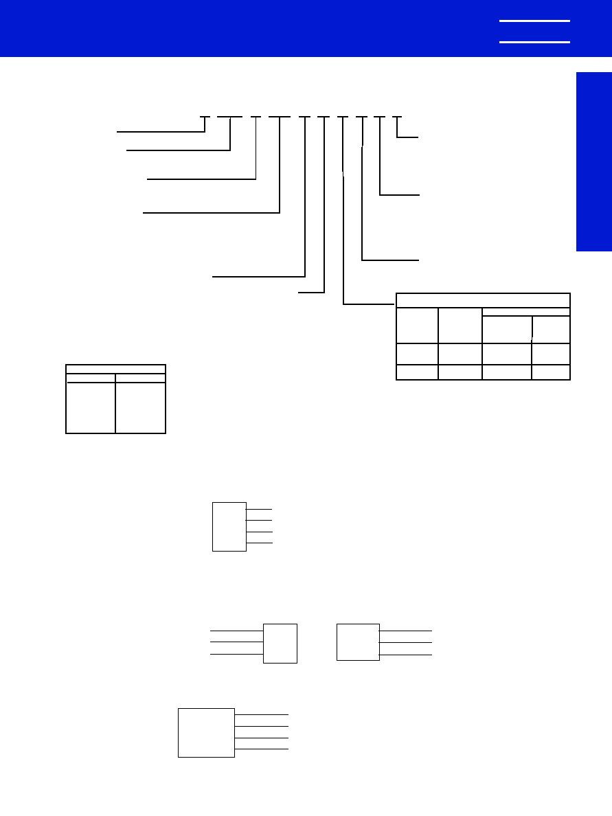
M
102
320
C
5
C
A
R
1
C
CERAMIC
CASE SIZE
(See Table Above)
SPECIFICATION
C -- Standard
CAPACITANCE, CODE
Expressed in Picofarads (pF)
First Two Digits -- Significant Figures
Third Digit -- Number of Zeros (Use 9 for 1.0
thru 9.9 pF. Example: 2.2pF -- 229)
FAILURE RATE
INTERNAL
CONSTRUCTION
CAPACITANCE TOLERANCE
D --
�
0.5 pF
F --
�
1%
G --
�
2%
J --
�
5%
A -- Not Applicable
K --
�
10%
M --
�
20%
Z -- -20, +80%
LEAD MATERIAL
C -- Standard
5 -- Standard
DIELECTRIC
EIA Designation
G -- C0G (NP0) -- Ultra-Stable
R -- X7R -- Stable
U -- Z5U -- General Purpose
RATED VOLTAGE
2 -- 200
1 -- 100
5 --
50
*
*Part Number Example: C320C102M1R5CA (14 digits � no spaces)
ORDERING INFORMATION
Drawings are not to scale. See table below for dimensions.
See page 9 for optional lead configurations.
STANDARD LEAD CONFIGURATION -- OUTLINE DRAWINGS
0988 Layout rev 8/9/2000 9:54 AM Page 8
KEMET Electronics Corporation, P.O. Box 5928, Greenville, S.C. 29606, (864) 963-6300
9
KEMET
�
CERAMIC CONFORMALLY COATED/RADIAL
"GOLDEN MAX"
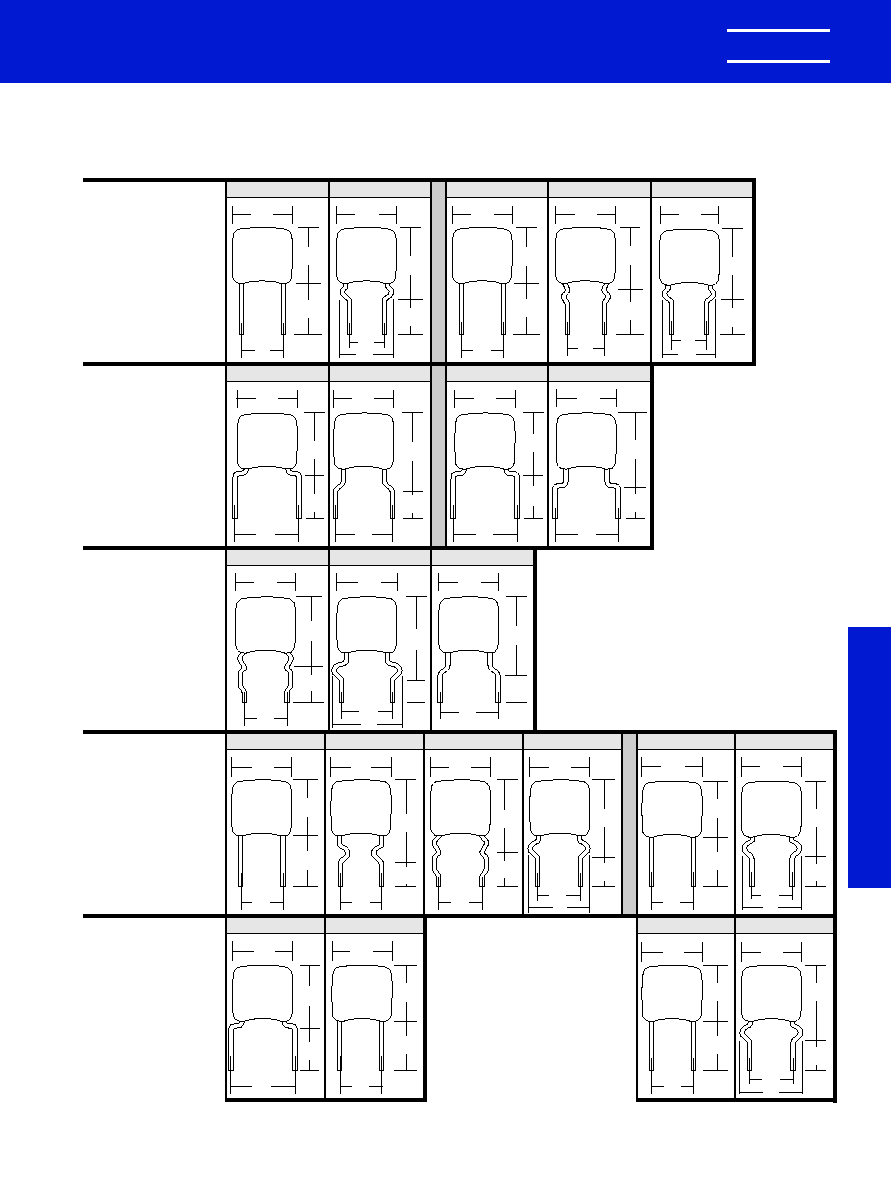
Lead Spacing
.100"
�
.030
Lead Spacing
.200"
�
.030
Lead Spacing
.200"
�
.030
Lead Spacing
.200"
�
.030
Lead Spacing
.250"
�
.030
Lead Spacing
.400"
�
.030
.150
MAX.
.210
MAX.
.276
MIN.
.100
C 3 1 5
.150
MAX.
.230
MAX.
.230
�
.030
.100
C 3 1 6
.200
.200
MAX.
.260
MAX.
.276
MIN.
.200
C 3 2 2
C 3 2 3
.320
MAX.
.276
MIN.
.200
.200
MAX.
.150
MAX.
.230
MAX.
.276
MIN.
.200
C 3 1 7
.150
MAX.
.235
MAX.
.276
MIN.
.200
C 3 1 8
.200
MAX.
.325
MAX.
.276
MIN.
C 3 2 8
.200
.200
MAX.
.350
MAX.
.230
�
.030
.200
C 3 2 7
.270
.200
MAX.
.320
MAX.
.276
MIN.
.200
C 3 2 5
.300
MAX.
.360
MAX.
.276
MIN.
.250
C 3 3 1
.200
MAX.
.260
MAX.
.276
MIN.
.250
C 3 2 1
.500
MAX.
.560
MAX.
.276
MIN.
.400
C 3 5 0
.500
MAX.
.670
MAX.
.230
�
.030
C 3 5 6
.400
.520
.400
MAX.
.590
MAX.
.230
�
.030
.200
C 3 4 6
.320
.400
MAX.
.460
MAX.
.276
MIN.
.200
C 3 4 0
.200
MAX.
.260
MAX.
.276
MIN.
.100
C 3 2 0
.200
MAX.
.260
MAX.
.276
MIN.
.100
C 3 2 4
C 3 2 6
.230
�
.030
.100
.200
.200
MAX.
.350
MAX.
.300
MAX.
.360
MAX.
.276
MIN.
.200
C 3 3 0
.300
MAX.
.390
MAX.
.276
MIN.
.200
C 3 3 3
.300
MAX.
.420
MAX.
.276
MIN.
.200
C 3 3 5
.300
MAX.
.450
MAX.
.230
�
.030
.200
C 3 3 6
.300
The preferred lead wire configurations are shown on page 8. However, additional configurations are
available. All available options, including those on page 8, are shown below grouped by lead spacing.
OPTIONAL CONFIGURATIONS BY LEAD SPACING
Golden Max
0988 Layout rev 8/9/2000 9:54 AM Page 9
KEMET Electronics Corporation, P.O. Box 5928, Greenville, S.C. 29606, (864) 963-6300
10
KEMET
�
KEMET
CAPACITANCE
PART NUMBER
100 VOLT -- C31X SIZE
120 pF
C31(1)C121(3)1G5CA
150 pF
C31(1)C151(3)1G5CA
180 pF
C31(1)C181(3)1G5CA
220 pF
C31(1)C221(3)1G5CA
270 pF
C31(1)C271(3)1G5CA
330 pF
C31(1)C331(3)1G5CA
390 pF
C31(1)C391(3)1G5CA
470 pF
C31(1)C471(3)1G5CA
560 pF
C31(1)C561(3)1G5CA
680 pF
C31(1)C681(3)1G5CA
820 pF
C31(1)C821(3)1G5CA
1,000 pF
C31(1)C102(3)1G5CA
100 VOLT -- C32X SIZE
680 pF
C32(2)C681(3)1G5CA
820 pF
C32(2)C821(3)1G5CA
1,000 pF
C32(2)C102(3)1G5CA
1,200 pF
C32(2)C122(3)1G5CA
1,500 pF
C32(2)C152(3)1G5CA
1,800 pF
C32(2)C182(3)1G5CA
2,200 pF
C32(2)C222(3)1G5CA
2,700 pF
C32(2)C272(3)1G5CA
3,300 pF
C32(2)C332(3)1G5CA
3,900 pF
C32(2)C392(3)1G5CA
4,700 pF
C32(2)C472(3)1G5CA
5,600 pF
C32(2)C562(3)1G5CA
100 VOLT -- C33X SIZE
3,300 pF
C33(4)C332(3)1G5CA
3,900 pF
C33(4)C392(3)1G5CA
4,700 pF
C33(4)C472(3)1G5CA
5,600 pF
C33(4)C562(3)1G5CA
6,800 pF
C33(4)C682(3)1G5CA
8,200 pF
C33(4)C822(3)1G5CA
.01 �F
C33(4)C103(3)1G5CA
.012 �F
C33(4)C123(3)1G5CA
.015 �F
C33(4)C153(3)1G5CA
.018 �F
C33(4)C183(3)1G5CA
.022 �F
C33(4)C223(3)1G5CA
.027 �F
C33(4)C273(3)1G5CA
100 VOLT -- C340 SIZE
.027 �F
C340C273(3)1G5CA
.033 �F
C340C333(3)1G5CA
.039 �F
C340C393(3)1G5CA
.047 �F
C340C473(3)1G5CA
.056 �F
C340C563(3)1G5CA
.068 �F
C340C683(3)1G5CA
100 VOLT -- C350 SIZE
.039 �F
C350C393(3)1G5CA
.047 �F
C350C473(3)1G5CA
.056 �F
C350C563(3)1G5CA
.068 �F
C350C683(3)1G5CA
.082 �F
C350C823(3)1G5CA
.1 �F
C350C104(3)1G5CA
.12 �F
C350C124(3)1G5CA
CERAMIC CONFORMALLY COATED/RADIAL
"GOLDEN MAX"
RATINGS & PART NUMBER REFERENCE: ULTRA-STABLE TEMPERATURE CHARACTERISTICS -- C0G
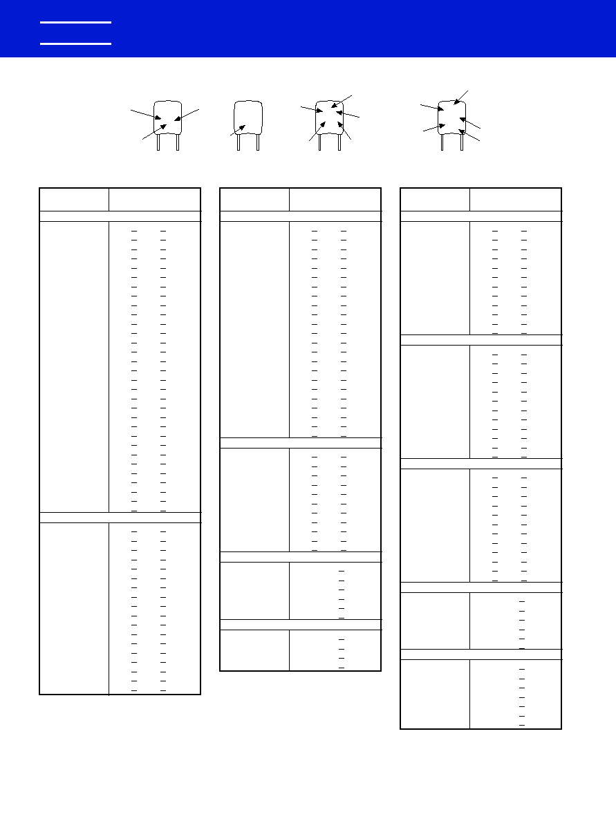
CAPACITOR MARKINGS
KEMET
CAPACITANCE
PART NUMBER
200 VOLT -- C31X SIZE
1.0 pF
C31(1)C109(3)2G5CA
1.5 pF
C31(1)C159(3)2G5CA
2.2 pF
C31(1)C229(3)2G5CA
2.7 pF
C31(1)C279(3)2G5CA
3.3 pF
C31(1)C339(3)2G5CA
3.9 pF
C31(1)C399(3)2G5CA
4.7 pF
C31(1)C479(3)2G5CA
5.6 pF
C31(1)C569(3)2G5CA
6.8 pF
C31(1)C689(3)2G5CA
8.2 pF
C31(1)C829(3)2G5CA
10 pF
C31(1)C100(3)2G5CA
12 pF
C31(1)C120(3)2G5CA
15 pF
C31(1)C150(3)2G5CA
18 pF
C31(1)C180(3)2G5CA
22 pF
C31(1)C220(3)2G5CA
27 pF
C31(1)C270(3)2G5CA
33 pF
C31(1)C330(3)2G5CA
39 pF
C31(1)C390(3)2G5CA
47 pF
C31(1)C470(3)2G5CA
56 pF
C31(1)C560(3)2G5CA
68 pF
C31(1)C680(3)2G5CA
82 pF
C31(1)C820(3)2G5CA
100 pF
C31(1)C101(3)2G5CA
120 pF
C31(1)C121(3)2G5CA
150 pF
C31(1)C151(3)2G5CA
180 pF
C31(1)C181(3)2G5CA
220 pF
C31(1)C221(3)2G5CA
270 pF
C31(1)C271(3)2G5CA
330 pF
C31(1)C331(3)2G5CA
390 pF
C31(1)C391(3)2G5CA
470 pF
C31(1)C471(3)2G5CA
200 VOLT -- C32X SIZE
1.0 pF
C32(2)C109(3)2G5CA
1.5 pF
C32(2)C159(3)2G5CA
2.2 pF
C32(2)C229(3)2G5CA
2.7 pF
C32(2)C279(3)2G5CA
3.3 pF
C32(2)C339(3)2G5CA
3.9 pF
C32(2)C399(3)2G5CA
4.7 pF
C32(2)C479(3)2G5CA
5.6 pF
C32(2)C569(3)2G5CA
6.8 pF
C32(2)C689(3)2G5CA
8.2 pF
C32(2)C829(3)2G5CA
10 pF
C32(2)C100(3)2G5CA
12 pF
C32(2)C120(3)2G5CA
15 pF
C32(2)C150(3)2G5CA
18 pF
C32(2)C180(3)2G5CA
22 pF
C32(2)C220(3)2G5CA
27 pF
C32(2)C270(3)2G5CA
33 pF
C32(2)C330(3)2G5CA
39 pF
C32(2)C390(3)2G5CA
KEMET
CAPACITANCE
PART NUMBER
200 VOLT -- C32X SIZE (Cont'd)
47 pF
C32(2)C470(3)2G5CA
56 pF
C32(2)C560(3)2G5CA
68 pF
C32(2)C680(3)2G5CA
82 pF
C32(2)C820(3)2G5CA
100 pF
C32(2)C101(3)2G5CA
120 pF
C32(2)C121(3)2G5CA
150 pF
C32(2)C151(3)2G5CA
180 pF
C32(2)C181(3)2G5CA
220 pF
C32(2)C221(3)2G5CA
270 pF
C32(2)C271(3)2G5CA
330 pF
C32(2)C331(3)2G5CA
390 pF
C32(2)C391(3)2G5CA
470 pF
C32(2)C471(3)2G5CA
560 pF
C32(2)C561(3)2G5CA
680 pF
C32(2)C681(3)2G5CA
820 pF
C32(2)C821(3)2G5CA
1,000 pF
C32(2)C102(3)2G5CA
1,200 pF
C32(2)C122(3)2G5CA
1,500 pF
C32(2)C152(3)2G5CA
1,800 pF
C32(2)C182(3)2G5CA
2,200 pF
C32(2)C222(3)2G5CA
2,700 pF
C32(2)C272(3)2G5CA
3,300 pF
C32(2)C332(3)2G5CA
200 VOLT -- C33X SIZE
2,700 pF
C33(4)C272(3)2G5CA
3,300 pF
C33(4)C332(3)2G5CA
3,900 pF
C33(4)C392(3)2G5CA
4,700 pF
C33(4)C472(3)2G5CA
5,600 pF
C33(4)C562(3)2G5CA
6,800 pF
C33(4)C682(3)2G5CA
8,200 pF
C33(4)C822(3)2G5CA
.01 �F
C33(4)C103(3)2G5CA
.012 �F
C33(4)C123(3)2G5CA
.015 �F
C33(4)C153(3)2G5CA
.018 �F
C33(4)C183(3)2G5CA
200 VOLT -- C340 SIZE
.018 �F
C340C183(3)2G5CA
.022 �F
C340C223(3)2G5CA
.027 �F
C340C273(3)2G5CA
.033 �F
C340C333(3)2G5CA
.039 �F
C340C393(3)2G5CA
.047 �F
C340C473(3)2G5CA
200 VOLT -- C350 SIZE
.039 �F
C350C393(3)2G5CA
.047 �F
C350C473(3)2G5CA
.056 �F
C350C563(3)2G5CA
.068 �F
C350C683(3)2G5CA
NOTES: (1) Case Sizes C315/C317 are identical electrically, but differ in lead spacing. See table of dimensions. Insert the appropriate symbol, "5" or "7" in the part number.
(2) Case Sizes C320/C322/C323 are identical electrically. See table of dimensions. Insert the appropriate symbol, "0" or "2" or "3" in the part number.
(3) Insert proper symbol for capacitance tolerance as follows:
1.0 pF � 8.2 pF: D � � 0.5pF
10 pF � 22 pF: J � �5%, K � �10%
27 pF � 47 pF: G � �2%, J � �5%, K � �10%
56 pF and up: F � �1%, G � �2%, J � �5%
(4) Case Sizes C330 and C333 are identical electrically. Insert the appropriate symbol "0" or "3" in the part number.
Manufacturer
(KEMET)
Rated Voltage
5 - 50 volts
1 - 100 volts
2 - 200 volts
Capacitance
Tolerance
Manufacturer
(KEMET)
Capacitance
& Tolerance
Dielectric
C0G
X7R
Z5U
Rated
Voltage
Capacitance
Code
Date Code
Front
K1K
Back
102
C31X & C32X Size
KX7R
105K
100V
0012
C340 & C350 Size
Rated Voltage
5 - 50 volts
1 - 100 volts
2 - 200 volts
Manufacturer
(KEMET)
Capacitance
Tolerance
Capacitance
Code
Dielectric
G - C0G
R - X7R
U - Z5U
K5U
104M
C33X Size
0988 Layout rev 8/9/2000 9:54 AM Page 10
KEMET Electronics Corporation, P.O. Box 5928, Greenville, S.C. 29606, (864) 963-6300
11
KEMET
�
KEMET
CAPACITANCE
PART NUMBER
100 VOLT -- C31X SIZE
820 pF
C31(1)C821(3)1R5CA
1,000 pF
C31(1)C102(3)1R5CA
1,200 pF
C31(1)C122(3)1R5CA
1,500 pF
C31(1)C152(3)1R5CA
1,800 pF
C31(1)C182(3)1R5CA
2,200 pF
C31(1)C222(3)1R5CA
2,700 pF
C31(1)C272(3)1R5CA
3,300 pF
C31(1)C332(3)1R5CA
3,900 pF
C31(1)C392(3)1R5CA
4,700 pF
C31(1)C472(3)1R5CA
5,600 pF
C31(1)C562(3)1R5CA
6,800 pF
C31(1)C682(3)1R5CA
8,200 pF
C31(1)C822(3)1R5CA
.01 �F
C31(1)C103(3)1R5CA
100 VOLT -- C32X SIZE
4,700 pF
C32(2)C472(3)1R5CA
5,600 pF
C32(2)C562(3)1R5CA
6,800 pF
C32(2)C682(3)1R5CA
8,200 pF
C32(2)C822(3)1R5CA
.01 �F
C32(2)C103(3)1R5CA
.012 �F
C32(2)C123(3)1R5CA
.015 �F
C32(2)C153(3)1R5CA
.018 �F
C32(2)C183(3)1R5CA
.022 �F
C32(2)C223(3)1R5CA
.027 �F
C32(2)C273(3)1R5CA
.033 �F
C32(2)C333(3)1R5CA
.039 �F
C32(2)C393(3)1R5CA
.047 �F
C32(2)C473(3)1R5CA
.056 �F
C32(2)C563(3)1R5CA
.068 �F
C32(2)C683(3)1R5CA
.082 �F
C32(2)C823(3)1R5CA
.1 �F
C32(2)C104(3)1R5CA
100 VOLT -- C33X SIZE
.068 �F
C33(4)C683(3)1R5CA
.082 �F
C33(4)C823(3)1R5CA
.1 �F
C33(4)C104(3)1R5CA
.12 �F
C33(4)C124(3)1R5CA
.15 �F
C33(4)C154(3)1R5CA
.18 �F
C33(4)C184(3)1R5CA
.22 �F
C33(4)C224(3)1R5CA
.27 �F
C33(4)C274(3)1R5CA
.33 �F
C33(4)C334(3)1R5CA
.39 �F
C33(4)C394(3)1R5CA
.47 �F
C33(4)C474(3)1R5CA
100 VOLT -- C340 SIZE
.47 �F
C340C474(3)1R5CA
.56 �F
C340C564(3)1R5CA
.68 �F
C340C684(3)1R5CA
.82 �F
C340C824(3)1R5CA
1.0 �F
C340C105(3)1R5CA
100 VOLT -- C350 SIZE
.68 �F
C350C684(3)1R5CA
.82 �F
C350C824(3)1R5CA
1.0 �F
C350C105(3)1R5CA
1.2 �F
C350C125(3)1R5CA
CERAMIC CONFORMALLY COATED/RADIAL
"GOLDEN MAX"
KEMET
CAPACITANCE
PART NUMBER
50 VOLT -- C31X SIZE
3,300 pF
C31(1)C332(3)5R5CA
3,900 pF
C31(1)C392(3)5R5CA
4,700 pF
C31(1)C472(3)5R5CA
5,600 pF
C31(1)C562(3)5R5CA
6,800 pF
C31(1)C682(3)5R5CA
8,200 pF
C31(1)C822(3)5R5CA
.01 �F
C31(1)C103(3)5R5CA
.012 �F
C31(1)C123(3)5R5CA
.015 �F
C31(1)C153(3)5R5CA
.018 �F
C31(1)C183(3)5R5CA
.022 �F
C31(1)C223(3)5R5CA
.027 �F
C31(1)C273(3)5R5CA
.033 �F
C31(1)C333(3)5R5CA
50 VOLT -- C32X SIZE
.012 �F
C32(2)C123(3)5R5CA
.015 �F
C32(2)C153(3)5R5CA
.018 �F
C32(2)C183(3)5R5CA
.022 �F
C32(2)C223(3)5R5CA
.027 �F
C32(2)C273(3)5R5CA
.033 �F
C32(2)C333(3)5R5CA
.039 �F
C32(2)C393(3)5R5CA
.047 �F
C32(2)C473(3)5R5CA
.056 �F
C32(2)C563(3)5R5CA
.068 �F
C32(2)C683(3)5R5CA
.082 �F
C32(2)C823(3)5R5CA
.1 �F
C32(2)C104(3)5R5CA
.12 �F
C32(2)C124(3)5R5CA
.15 �F
C32(2)C154(3)5R5CA
.18 �F
C32(2)C184(3)5R5CA
.22 �F
C32(2)C224(3)5R5CA
.27 �F
C32(2)C274(3)5R5CA
50 VOLT -- C33X SIZE
.15 �F
C33(4)C154(3)5R5CA
.18 �F
C33(4)C184(3)5R5CA
.22 �F
C33(4)C224(3)5R5CA
.27 �F
C33(4)C274(3)5R5CA
.33 �F
C33(4)C334(3)5R5CA
.39 �F
C33(4)C394(3)5R5CA
.47 �F
C33(4)C474(3)5R5CA
.56 �F
C33(4)C564(3)5R5CA
.68 �F
C33(4)C684(3)5R5CA
.82 �F
C33(4)C824(3)5R5CA
1.0 �F
C33(4)C105(3)5R5CA
50 VOLT -- C340 SIZE
1.2 �F
C340C125(3)5R5CA
1.5 �F
C340C155(3)5R5CA
1.8 �F
C340C185(3)5R5CA
2.2 �F
C340C225(3)5R5CA
50 VOLT -- C350 SIZE
2.2 �F
C350C225(3)5R5CA
2.7 �F
C350C275(3)5R5CA
3.3 �F
C350C335(3)5R5CA
3.9 �F
C350C395(3)5R5CA
4.7 �F
C350C475(3)5R5CA
RATINGS & PART NUMBER REFERENCE: STABLE TEMPERATURE CHARACTERISTICS -- X7R
NOTES: (1) Case Sizes C315/C317 are identical electrically, but differ in lead spacing. See table of dimensions. Insert the appropriate symbol, "5" or "7" in the part number.
(2) Case Sizes C320/C322/C323 are identical electrically. See table of dimensions. Insert the appropriate symbol, "0" or "2" or "3" in the part number.
(3) Insert proper symbol for capacitance tolerance as follows: K � �10%, M � �20%
(4) Case Sizes C330 and C333 are identical electrically. Insert the appropriate symbol "0" or "3" in the part number.
KEMET
CAPACITANCE
PART NUMBER
200 VOLT -- C31X SIZE
100 pF
C31(1)C101(3)2R5CA
120 pF
C31(1)C121(3)2R5CA
150 pF
C31(1)C151(3)2R5CA
180 pF
C31(1)C181(3)2R5CA
220 pF
C31(1)C221(3)2R5CA
270 pF
C31(1)C271(3)2R5CA
330 pF
C31(1)C331(3)2R5CA
390 pF
C31(1)C391(3)2R5CA
470 pF
C31(1)C471(3)2R5CA
560 pF
C31(1)C561(3)2R5CA
680 pF
C31(1)C681(3)2R5CA
820 pF
C31(1)C821(3)2R5CA
1,000 pF
C31(1)C102(3)2R5CA
1,200 pF
C31(1)C122(3)2R5CA
1,500 pF
C31(1)C152(3)2R5CA
1,800 pF
C31(1)C182(3)2R5CA
2,200 pF
C31(1)C222(3)2R5CA
200 VOLT -- C32X SIZE
1,000 pF
C32(2)C102(3)2R5CA
1,200 pF
C32(2)C122(3)2R5CA
1,500 pF
C32(2)C152(3)2R5CA
1,800 pF
C32(2)C182(3)2R5CA
2,200 pF
C32(2)C222(3)2R5CA
2,700 pF
C32(2)C272(3)2R5CA
3,300 pF
C32(2)C332(3)2R5CA
3,900 pF
C32(2)C392(3)2R5CA
4,700 pF
C32(2)C472(3)2R5CA
5,600 pF
C32(2)C562(3)2R5CA
6,800 pF
C32(2)C682(3)2R5CA
8,200 pF
C32(2)C822(3)2R5CA
.01 �F
C32(2)C103(3)2R5CA
.012 �F
C32(2)C123(3)2R5CA
.015 �F
C32(2)C153(3)2R5CA
.018 �F
C32(2)C183(3)2R5CA
.022 �F
C32(2)C223(3)2R5CA
200 VOLT -- C33X SIZE
.015 �F
C33(4)C153(3)2R5CA
.018 �F
C33(4)C183(3)2R5CA
.022 �F
C33(4)C223(3)2R5CA
.027 �F
C33(4)C273(3)2R5CA
.033 �F
C33(4)C333(3)2R5CA
.039 �F
C33(4)C393(3)2R5CA
.047 �F
C33(4)C473(3)2R5CA
.056 �F
C33(4)C563(3)2R5CA
.068 �F
C33(4)C683(3)2R5CA
.082 �F
C33(4)C823(3)2R5CA
.1 �F
C33(4)C104(3)2R5CA
200 VOLT -- C340 SIZE
.1 �F
C340C104(3)2R5CA
.12 �F
C340C124(3)2R5CA
.15 �F
C340C154(3)2R5CA
.18 �F
C340C184(3)2R5CA
.22 �F
C340C224(3)2R5CA
.27 �F
C340C274(3)2R5CA
200 VOLT -- C350 SIZE
.22 �F
C350C224(3)2R5CA
.27 �F
C350C274(3)2R5CA
.33 �F
C350C334(3)2R5CA
.39 �F
C350C394(3)2R5CA
.47 �F
C350C474(3)2R5CA
Golden Max
0988 Layout rev 8/9/2000 9:54 AM Page 11
KEMET Electronics Corporation, P.O. Box 5928, Greenville, S.C. 29606, (864) 963-6300
12
KEMET
�
CERAMIC CONFORMALLY COATED/RADIAL
"GOLDEN MAX"
RATINGS & PART NUMBER REFERENCE
GENERAL PURPOSE TEMPERATURE CHARACTERISTIC -- Z5U
KEMET
CAPACITANCE
PART NUMBER
50 VOLT -- C31X SIZE
4,700 pF
C31(1)C472(3)5U5CA
5,600 pF
C31(1)C562(3)5U5CA
6,800 pF
C31(1)C682(3)5U5CA
8,200 pF
C31(1)C822(3)5U5CA
.01 �F
C31(1)C103(3)5U5CA
.012 �F
C31(1)C123(3)5U5CA
.015 �F
C31(1)C153(3)5U5CA
.018 �F
C31(1)C183(3)5U5CA
.022 �F
C31(1)C223(3)5U5CA
.027 �F
C31(1)C273(3)5U5CA
.033 �F
C31(1)C333(3)5U5CA
.039 �F
C31(1)C393(3)5U5CA
.047 �F
C31(1)C473(3)5U5CA
.056 �F
C31(1)C563(3)5U5CA
.068 �F
C31(1)C683(3)5U5CA
.082 �F
C31(1)C823(3)5U5CA
0.1 �F
C31(1)C104(3)5U5CA
50 VOLT -- C32X SIZE
.027 �F
C32(2)C273(3)5U5CA
.033 �F
C32(2)C333(3)5U5CA
.039 �F
C32(2)C393(3)5U5CA
.047 �F
C32(2)C473(3)5U5CA
.056 �F
C32(2)C563(3)5U5CA
.068 �F
C32(2)C683(3)5U5CA
.082 �F
C32(2)C823(3)5U5CA
0.1 �F
C32(2)C104(3)5U5CA
.12 �F
C32(2)C124(3)5U5CA
.15 �F
C32(2)C154(3)5U5CA
.18 �F
C32(2)C184(3)5U5CA
.22 �F
C32(2)C224(3)5U5CA
.27 �F
C32(2)C274(3)5U5CA
.33 �F
C32(2)C334(3)5U5CA
.39 �F
C32(2)C394(3)5U5CA
.47 �F
C32(2)C474(3)5U5CA
.56 �F
C32(2)C564(3)5U5CA
50 VOLT -- C33X SIZE
.27 �F
C33(4)C274(3)5U5CA
.33 �F
C33(4)C334(3)5U5CA
.39 �F
C33(4)C394(3)5U5CA
.47 �F
C33(4)C474(3)5U5CA
.56 �F
C33(4)C564(3)5U5CA
.68 �F
C33(4)C684(3)5U5CA
.82 �F
C33(4)C824(3)5U5CA
1.0 �F
C33(4)C105(3)5U5CA
1.2 �F
C33(4)C125(3)5U5CA
1.5 �F
C33(4)C155(3)5U5CA
1.8 �F
C33(4)C185(3)5U5CA
2.2 �F
C33(4)C225(3)5U5CA
50 VOLT -- C340 SIZE
2.2 �F
C340C225(3)5U5CA
2.7 �F
C340C275(3)5U5CA
3.3 �F
C340C335(3)5U5CA
3.9 �F
C340C395(3)5U5CA
4.7 �F
C340C475(3)5U5CA
50 VOLT -- C350 SIZE
3.9 �F
C350C395(3)5U5CA
4.7 �F
C350C475(3)5U5CA
5.6 �F
C350C565(3)5U5CA
6.8 �F
C350C685(3)5U5CA
NOTES: (1) Case Sizes C315/C317 are identical electrically, but differ in lead spacing. See table of dimensions. Insert the appropriate
symbol, "5" or "7" in the part number.
(2) Case Sizes C320/C322/C323 are identical electrically. See table of dimensions.
Insert the appropriate symbol, "0" or "2" or "3" in the part number.
(3) Insert proper symbol for capacitance tolerance as follows:
M � �20%
Z � +80%, -20%
(4) Case Sizes C330 and C333 are identical electrically. Insert the appropriate symbol "0" or "3" in the part number.
KEMET
CAPACITANCE
PART NUMBER
100 VOLT -- C31X SIZE
1,000 pF
C31(1)C102(3)1U5CA
1,200 pF
C31(1)C122(3)1U5CA
1,500 pF
C31(1)C152(3)1U5CA
1,800 pF
C31(1)C182(3)1U5CA
2,200 pF
C31(1)C222(3)1U5CA
2,700 pF
C31(1)C272(3)1U5CA
3,300 pF
C31(1)C332(3)1U5CA
3,900 pF
C31(1)C392(3)1U5CA
4,700 pF
C31(1)C472(3)1U5CA
5,600 pF
C31(1)C562(3)1U5CA
6,800 pF
C31(1)C682(3)1U5CA
8,200 pF
C31(1)C822(3)1U5CA
.01 �F
C31(1)C103(3)1U5CA
.012 �F
C31(1)C123(3)1U5CA
.015 �F
C31(1)C153(3)1U5CA
.018 �F
C31(1)C183(3)1U5CA
100 VOLT -- C32X SIZE
.01 �F
C32(2)C103(3)1U5CA
.012 �F
C32(2)C123(3)1U5CA
.015 �F
C32(2)C153(3)1U5CA
.018 �F
C32(2)C183(3)1U5CA
.022 �F
C32(2)C223(3)1U5CA
.027 �F
C32(2)C273(3)1U5CA
.033 �F
C32(2)C333(3)1U5CA
.039 �F
C32(2)C393(3)1U5CA
.047 �F
C32(2)C473(3)1U5CA
.056 �F
C32(2)C563(3)1U5CA
.068 �F
C32(2)C683(3)1U5CA
.082 �F
C32(2)C823(3)1U5CA
0.1 �F
C32(2)C104(3)1U5CA
.12 �F
C32(2)C124(3)1U5CA
.15 �F
C32(2)C154(3)1U5CA
100 VOLT -- C33X SIZE
0.1 �F
C33(4)C104(3)1U5CA
.12 �F
C33(4)C124(3)1U5CA
.15 �F
C33(4)C154(3)1U5CA
.18 �F
C33(4)C184(3)1U5CA
.22 �F
C33(4)C224(3)1U5CA
.27 �F
C33(4)C274(3)1U5CA
.33 �F
C33(4)C334(3)1U5CA
.39 �F
C33(4)C394(3)1U5CA
.47 �F
C33(4)C474(3)1U5CA
100 VOLT -- C340 SIZE
.47 �F
C340C474(3)1U5CA
.56 �F
C340C564(3)1U5CA
.68 �F
C340C684(3)1U5CA
.82 �F
C340C824(3)1U5CA
1.0 �F
C340C105(3)1U5CA
1.2 �F
C340C125(3)1U5CA
1.5 �F
C340C155(3)1U5CA
100 VOLT -- C350 SIZE
1.0 �F
C350C105(3)1U5CA
1.2 �F
C350C125(3)1U5CA
1.5 �F
C350C155(3)1U5CA
1.8 �F
C350C185(3)1U5CA
2.2 �F
C350C225(3)1U5CA
0988 Layout rev 8/9/2000 9:54 AM Page 12

KEMET Electronics Corporation, P.O. Box 5928, Greenville, S.C. 29606, (864) 963-6300
13
KEMET
�
CERAMIC MOLDED AXIAL & RADIAL
PERFORMANCE CHARACTERISTICS
Ceramic Molded
Axial &
Radial
GENERAL
Working Voltage:
C0G � 50, 100 & 200 Volts
X7R � 50, 100 & 200 Volts
Temperature Characteristics:
C0G � 0 �30 PPM/�C from -55�C to +125�C
X7R � �15% from -55�C to +125�C
Capacitance Tolerance:
C0G � �0.5 pF, �1%, �2%, �5%, �10%, �20%
(�0.5 pF is tightest available tolerance)
X7R � �10%, �20%, -0 +100%, -20% +80%
Construction:
Monolithic block of ceramic dielectric with interdigitated
internal electrodes, encapsulated in a molded case, and
having axial or radial leads. Meets flame test requirements
of UL Standard 94V-0.
Terminal Strength:
EIA-RS-198D Method 303 Condition A (2.2 kg)
ELECTRICAL
Capacitance:
Within specified tolerance when measured with 1 volt rms
at 1 kHz (1000 pF or less at 1 MHz for C0G).
Dissipation Factor:
25�C at 1 kHz (1000 pF or less at 1 MHz for C0G).
C0G � .15% maximum
X7R � 2.5% maximum
Insulation Resistance:
After 2 minutes electrification at 25�C and rated voltage
C0G � 100K megohms or 1000 megohm - �F, whichever
is less.
X7R � 100K megohms or 1000 megohm - �F, whichever
is less.
Dielectric Withstanding Voltage:
250% of rated voltage for 5 seconds with current limited
to 50 mA at 25�C.
Life Test:
2000 hours at 200% of rated voltage at 125�C. Post-Test
limits at 25�C are:
Capacitance Change:
C0G � less than 3% or 0.25 pF, whichever is higher
X7R � �20% of initial value
Dissipation Factor:
C0G � .25% maximum
X7R � 3.0% maximum
Insulation Resistance:
C0G � 10K megohms or 100 megohm - �F, whichever
is less
X7R � 10K megohms or 100 megohm - �F, whichever
is less
Dielectric Withstanding Voltage:
250% of rated voltage for 5 seconds with current
limited to 50 mA.
ENVIRONMENTAL
Moisture Resistance:
MIL-STD-202, Method 106, or EIA-RS-198D, Method 204,
Condition A, except 20 cycles.
Insulation Resistance:
C0G � 10K megohms or 100 megohm - �F, whichever
is less
X7R � 10K megohms or 100 megohm - �F, whichever
is less
Dielectric Withstanding Voltage:
250% of rated voltage for 5 seconds with current
limited to 50 mA.
Immersion Cycling:
MIL-STD-202, Method 104, Condition B. Post-Test limits
at 25�C are:
Insulation Resistance:
C0G � 10K megohms or 100 megohm - �F, whichever
is less
X7R � 10K megohms or 100 megohm - �F, whichever
is less
Solderability:
MIL-STD-202, Method 208, Sn62 solder, 245�C for 5 �1/2
seconds.
Resistance to Soldering Heat:
MIL-STD-202, Method 210, Condition B (260�C, 10 secs).
Depth of immersion -- to a minimum of .050" from the
capacitor body.
Lead Material:
Axial: Solder-coated copper clad steel
Radial: Solder-coated copper
0988 Layout rev 8/9/2000 9:54 AM Page 13
CERAMIC MOLDED/AXIAL & RADIAL - STANDARD
KEMET Electronics Corporation, P.O. Box 5928, Greenville, S.C. 29606, (864) 963-6300
14
KEMET
�
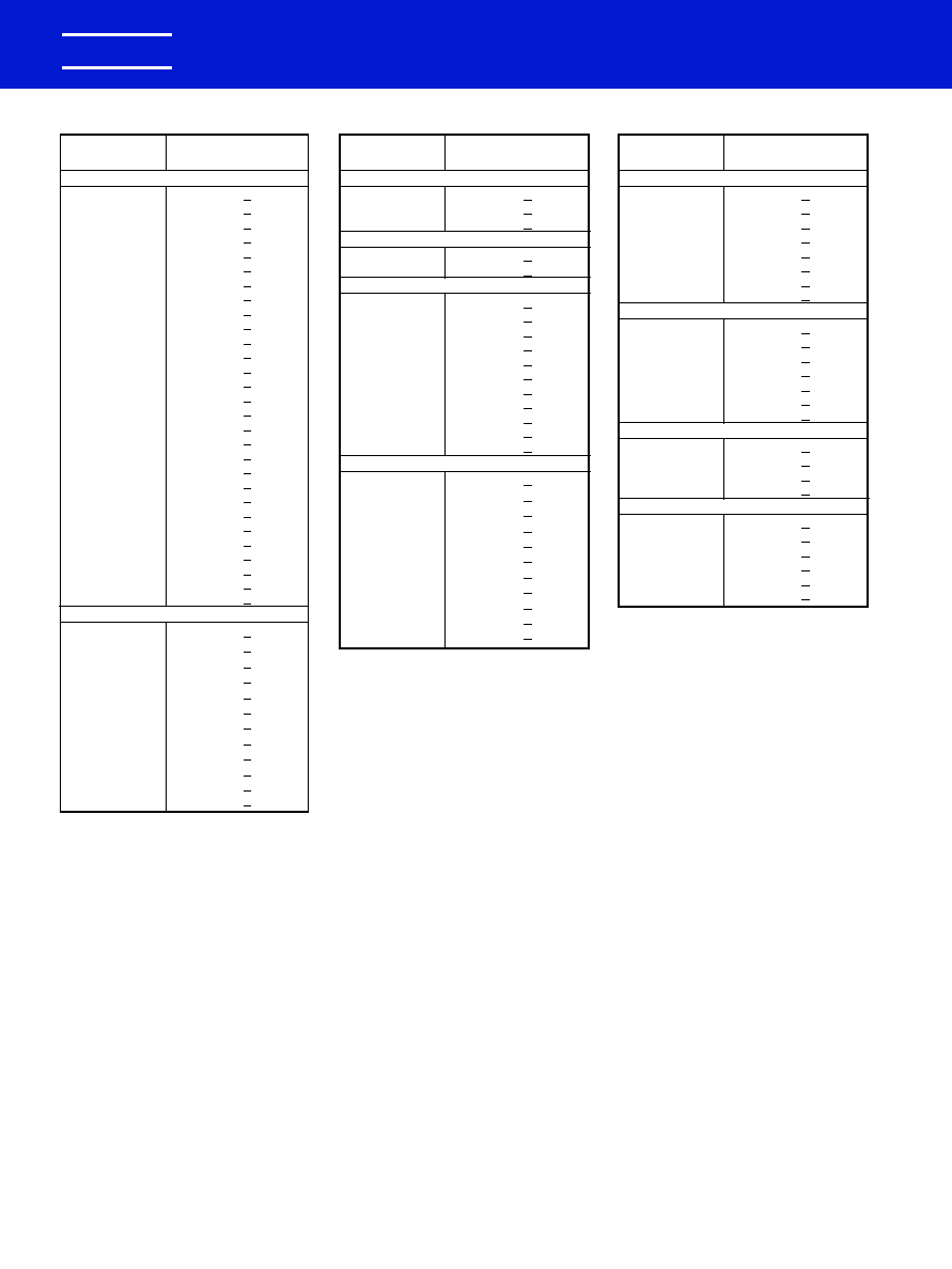
Lead Dia.
.025
(+.004
-.002)
S
H
1.25
Min.
W
Center Line of leads
within .030" of Center
Line of case.
H
1.25
Min.
L
S
W
.045
Max.
L
C052
C062,
C512,
& C522
Lead Dia.
.025
(+.004
-.002)
DIMENSIONS--INCHES & (MILLIMETERS)
CASE
MILITARY
SIZE
EQUIVALENT STYLES
L
D
C
C114
.160 � .010 (4.06 � .25)
.090 � .010 (2.29 � .25)
.020, +.000, -.003 (.51, +.00, -.08)
C124
.250 � .010 (6.35 � .25)
.090 � .010 (2.29 � .25)
.020, +.000, -.003 (.51, +.00, -.08)
C192
.390 � .010 (9.91 � .25)
.140 � .010 (3.56 � .25)
.025, +.004, -.001 (.64, +.10, -.025)
C202
.500 � .020 (12.70 � .51)
.250 � .015 (6.35 � .38)
.025, +.004, -.001 (.64, +.10, -.025)
C222
.690 � .030 (17.53 � .76)
.350 � .020 (8.89 � .51)
.025, +.004, -.001 (.64, +.10, -.025)
D
L
C
1.50 Min.
(38.10)
1.50 Min.
(38.10)
CAPACITOR OUTLINE DRAWINGS -- (AXIAL LEADS)
CC75, CCR75
CK12, CKR11
CC76, CCR76
CK13, CKR12
CC77, CCR77
CK14, CKR14
CC78, CCR78
CK15, CKR15
CC79, CCR79
CK16, CKR16
CAPACITOR OUTLINE DRAWINGS -- (RADIAL LEADS)
DIMENSIONS--INCHES & (MILLIMETERS)
MILITARY
S
CASE
EQUIVALENT
H
L
W
LEAD
SIZE
STYLES
HEIGHT
LENGTH
WIDTH
SPACING
C052
.190 � .010 (4.83 � .25)
.190 � .010 (4.83 � .25)
.090 � .010 (2.29 � .25)
.200 � .015 (5.08 � .38)
C062
.290 � .010 (7.37 � .25)
.290 � .010 (7.37 � .25)
.090 � .010 (2.29 � .25)
.200 � .015 (5.08 � .38)
C512
.480 � .020 (12.19 � .51)
.480 � .020 (12.19 � .51)
.140 � .010 (3.56 � .25)
.400 � .020 (10.16 � .51)
C522
.480 � .020 (12.19 � .51)
.480 � .020 (12.19 � .51)
.240 � .010 (6.10 � .25)
.400 � .020 (10.16 � .51)
CC05, CCR05
CK05, CKR05
CC06, CCR06
CK06, CKR06
CC07, CCR07
CC08, CCR08
For packaging information, see pages 32, 33 and 34.
0988 Layout rev 8/9/2000 9:54 AM Page 14
K
102
052
C
5
C
A
R
2
C
CERAMIC
*CASE SIZE
(See Table Below)
SPECIFICATION
Standard
C -- Standard
CAPACITANCE
In picofarad code: First two digits are significant
figures and third is number of zeroes following
(except 9 indicates division by 10). Examples:
0.1 F = 100,000 pF = 104 and 9.1 pF = 919.
See tables for Standard Values.
FAILURE RATE
INTERNAL CONSTRUCTION
CAPACITANCE TOLERANCE
Standard
M --
�
20%
K --
�
10%
J --
�
5%
A -- Not Applicable (Std.)
LEAD MATERIAL
C -- Standard
5 -- Standard
WORKING
VOLTAGE
1 -- 100
2 -- 200
5 --
50
Others
H --
�
3%
G --
�
2%
F --
�
1%
D --
�
.5 pF
TEMPERATURE CHARACTERISTIC
Cap. Change With Temp.
Measured
Without
KEMET
EIA
Temp.
DC Bias
Designator
Equivalent
Range,
�
C
Voltage
G
C0G
-55 to
�
30
(Ultra
(NPO)
+125
ppm/
�
C
Stable)
R
X7R
-55 to
�
15%
(Stable)
+125
Standard tolerances for each Series are
shown in the repetitive parts lists.
*CASE SIZES
RADIAL
AXIAL
C052
C114
C062
C124
C512
C192
C522
C202
C222
**
**Part Number Example: C052C102K2R5CA (14 digits � no spaces)
KEMET Electronics Corporation, P.O. Box 5928, Greenville, S.C. 29606, (864) 963-6300
15
KEMET
�
CERAMIC MOLDED/AXIAL & RADIAL - STANDARD
ORDERING INFORMATION
Ceramic Molded
Axial/Radial - Standar
d
AXIAL CAPACITOR MARKINGS
STANDARD C114C, C124C, C192C, C202C & C222C
KC0G
101J
200V
0012
KEMET, Temperature Characteristic
Capacitance, Capacitance Tolerance
Voltage
Date Code
RADIAL CAPACITOR MARKINGS
C052C & C062C STANDARD MARKING
100V
K
0011
Voltage
KEMET
Date Code
BACK
C062
X7R
104K
FRONT
Style
Temperature Characteristic
Capacitance, Capacitance Tolerance
C512 & C522 STANDARD MARKING
KEMET
C512X7R
105K 50V
0032
KEMET
SIZE and Temperature Characteristic
Capacitance, Capacitance Tolerance, Voltage
Date Code
0988 Layout rev 8/9/2000 9:54 AM Page 15
KEMET Electronics Corporation, P.O. Box 5928, Greenville, S.C. 29606, (864) 963-6300
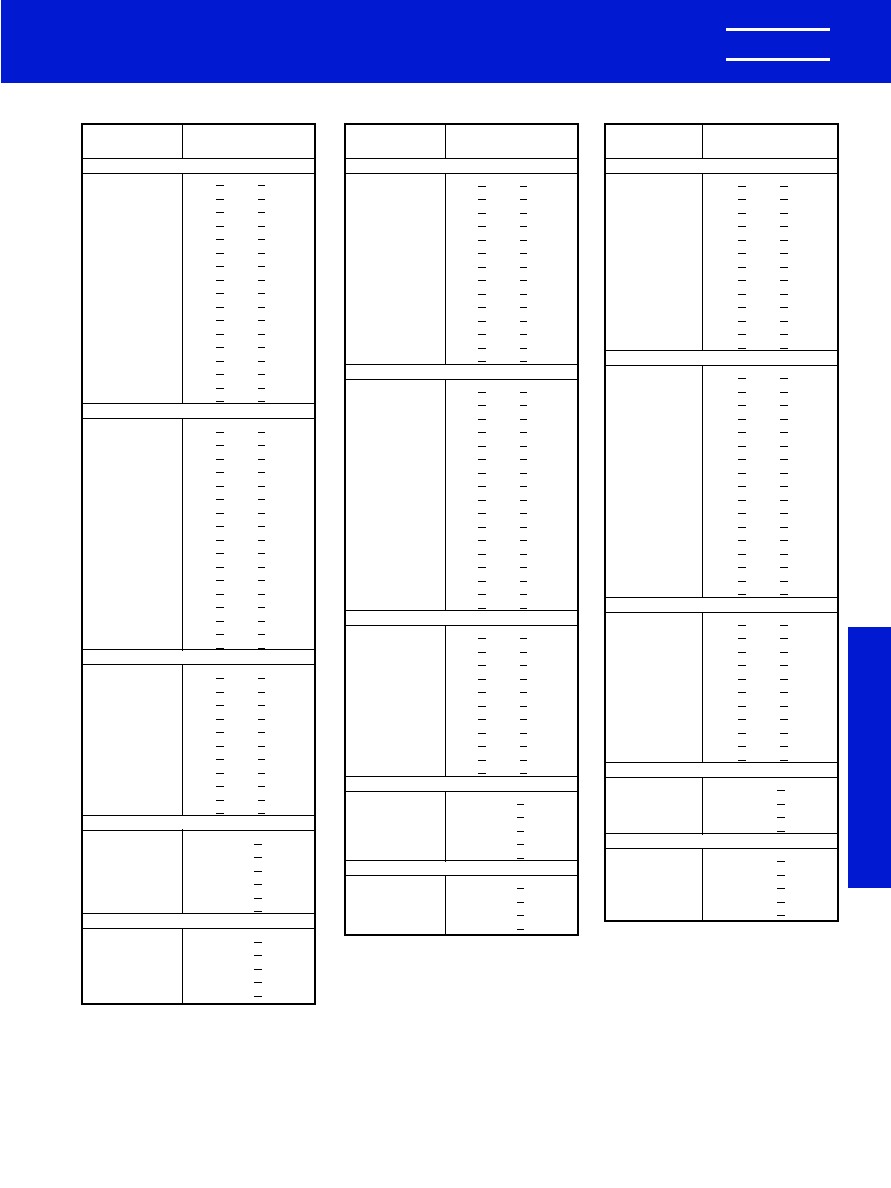
CAPACITANCE
KEMET
pF
PART NUMBER
200 VOLT -- C202 STANDARD C0G
5,600.0
C202C562(4)2G5CA
6,800.0
C202C682(4)2G5CA
8,200.0
C202C822(4)2G5CA
10,000.0
C202C103(4)2G5CA
12,000.0
C202C123(4)2G5CA
15,000.0
C202C153(4)2G5CA
18,000.0
C202C183(4)2G5CA
22,000.0
C202C223(4)2G5CA
100 VOLT -- C202 STANDARD C0G
10,000.0
C202C103(4)1G5CA
12,000.0
C202C123(4)1G5CA
15,000.0
C202C153(4)1G5CA
18,000.0
C202C183(4)1G5CA
22,000.0
C202C223(4)1G5CA
27,000.0
C202C273(4)1G5CA
33,000.0
C202C333(4)1G5CA
200 VOLT -- C222 STANDARD C0G
27,000.0
C222C273(4)2G5CA
33,000.0
C222C333(4)2G5CA
39,000.0
C222C393(4)2G5CA
47,000.0
C222C473(4)2G5CA
100 VOLT -- C222 STANDARD C0G
39,000.0
C222C393(4)1G5CA
47,000.0
C222C473(4)1G5CA
56,000.0
C222C563(4)1G5CA
68,000.0
C222C683(4)1G5CA
82,000.0
C222C823(4)1G5CA
100,000.0
C222C104(4)1G5CA
CERAMIC MOLDED/AXIAL � STANDARD
ULTRA-STABLE TEMPERATURE CHARACTERISTIC--C0G (NP0)
16
KEMET
�
CAPACITANCE
KEMET
pF
PART NUMBER
200 VOLT -- C124 STANDARD C0G
390.0
C124C391(4)2G5CA
470.0
C124C471(4)2G5CA
560.0
C124C561(4)2G5CA
100 VOLT -- C124 STANDARD C0G
820.0
C124C821(4)1G5CA
1,000.0
C124C102(4)1G5CA
200 VOLT -- C192 STANDARD C0G
680.0
C192C681(4)2G5CA
820.0
C192C821(4)2G5CA
1,000.0
C192C102(4)2G5CA
1,200.0
C192C122(4)2G5CA
1,500.0
C192C152(4)2G5CA
1,800.0
C192C182(4)2G5CA
2,200.0
C192C222(4)2G5CA
2,700.0
C192C272(4)2G5CA
3,300.0
C192C332(4)2G5CA
3,900.0
C192C392(4)2G5CA
4,700.0
C192C472(4)2G5CA
100 VOLT -- C192 STANDARD C0G
1,200.0
C192C122(4)1G5CA
1,500.0
C192C152(4)1G5CA
1,800.0
C192C182(4)1G5CA
2,200.0
C192C222(4)1G5CA
2,700.0
C192C272(4)1G5CA
3,300.0
C192C332(4)1G5CA
3,900.0
C192C392(4)1G5CA
4,700.0
C192C472(4)1G5CA
5,600.0
C192C562(4)1G5CA
6,800.0
C192C682(4)1G5CA
8,200.0
C192C822(4)1G5CA
RATINGS & PART NUMBER REFERENCE
CAPACITANCE
KEMET
pF
PART NUMBER
200 VOLT -- C114 STANDARD C0G
1.0
C114C109(1)2G5CA
1.5
C114C159(1)2G5CA
2.2
C114C229(1)2G5CA
2.7
C114C279(1)2G5CA
3.3
C114C339(1)2G5CA
3.9
C114C399(1)2G5CA
4.7
C114C479(1)2G5CA
5.6
C114C569(1)2G5CA
6.8
C114C689(1)2G5CA
8.2
C114C829(1)2G5CA
10.0
C114C100(2)2G5CA
12.0
C114C120(2)2G5CA
15.0
C114C150(2)2G5CA
18.0
C114C180(2)2G5CA
22.0
C114C220(2)2G5CA
27.0
C114C270(3)2G5CA
33.0
C114C330(3)2G5CA
39.0
C114C390(3)2G5CA
47.0
C114C470(3)2G5CA
56.0
C114C560(4)2G5CA
68.0
C114C680(4)2G5CA
82.0
C114C820(4)2G5CA
100.0
C114C101(4)2G5CA
120.0
C114C121(4)2G5CA
150.0
C114C151(4)2G5CA
180.0
C114C181(4)2G5CA
220.0
C114C221(4)2G5CA
270.0
C114C271(4)2G5CA
330.0
C114C331(4)2G5CA
100 VOLT -- C114 STANDARD C0G
82.0
C114C820(4)1G5CA
100.0
C114C101(4)1G5CA
120.0
C114C121(4)1G5CA
150.0
C114C151(4)1G5CA
180.0
C114C181(4)1G5CA
220.0
C114C221(4)1G5CA
270.0
C114C271(4)1G5CA
330.0
C114C331(4)1G5CA
390.0
C114C391(4)1G5CA
470.0
C114C471(4)1G5CA
560.0
C114C561(4)1G5CA
680.0
C114C681(4)1G5CA
NOTE 1: Insert proper symbol for capacitance tolerance as
follows:
(1) 1.0 pF to 8.2 pF: D-- �.5 pF
(2) 10.0 pF to 22 pF: J-- �5%, K-- �10%
(3) 27.0 pF to 47 pF: G-- �2%, J-- �5%, K-- �10%
(4) 56.0 pF and up: F-- �1%,G-- �2%, J-- �5%, K-- �10%
NOTE 1: Insert proper symbol for capacitance tolerance as
follows:
(1) 1.0 pF to 8.2 pF: D-- �.5 pF
(2) 10.0 pF to 22 pF: J-- �5%, K-- �10%
(3) 27.0 pF to 47 pF: G-- �2%, J-- �5%, K-- �10%
(4) 56.0 pF and up: F-- �1%,G-- �2%, J-- �5%, K-- �10%
NOTE 1: Insert proper symbol for capacitance tolerance as
follows:
(1) 1.0 pF to 8.2 pF: D-- �.5 pF
(2) 10.0 pF to 22 pF: J-- �5%, K-- �10%
(3) 27.0 pF to 47 pF: G-- �2%, J-- �5%, K-- �10%
(4) 56.0 pF and up: F-- �1%,G-- �2%, J-- �5%, K-- �10%
0988 Layout rev 8/9/2000 9:54 AM Page 16
KEMET Electronics Corporation, P.O. Box 5928, Greenville, S.C. 29606, (864) 963-6300
17
Ceramic Molded
Axial/Radial - Standar
d
KEMET
�
CERAMIC MOLDED/RADIAL � STANDARD
ULTRA-STABLE TEMPERATURE CHARACTERISTIC--C0G (NP0)
RATINGS & PART NUMBER REFERENCE
CAPACITANCE
KEMET
pF
PART NUMBER
200 VOLT -- C062 SIZE C0G
3,300.0
C062C332(4)2G5CA
3,900.0
C062C392(4)2G5CA
4,700.0
C062C472(4)2G5CA
5,600.0
C062C562(4)2G5CA
6,800.0
C062C682(4)2G5CA
8,200.0
C062C822(4)2G5CA
10,000.0
C062C103(4)2G5CA
100 VOLT -- C062 SIZE C0G
5,600.0
C062C562(4)1G5CA
6,800.0
C062C682(4)1G5CA
8,200.0
C062C822(4)1G5CA
10,000.0
C062C103(4)1G5CA
12,000.0
C062C123(4)1G5CA
15,000.0
C062C153(4)1G5CA
18,000.0
C062C183(4)1G5CA
22,000.0
C062C223(4)1G5CA
200 VOLT -- C512 SIZE C0G
12,000.0
C512C123(4)2G5CA
15,000.0
C512C153(4)2G5CA
18,000.0
C512C183(4)2G5CA
22,000.0
C512C223(4)2G5CA
27,000.0
C512C273(4)2G5CA
33,000.0
C512C333(4)2G5CA
39,000.0
C512C393(4)2G5CA
47,000.0
C512C473(4)2G5CA
56,000.0
C512C563(4)2G5CA
68,000.0
C512C683(4)2G5CA
100 VOLT -- C512 SIZE C0G
27,000.0
C512C273(4)1G5CA
33,000.0
C512C333(4)1G5CA
39,000.0
C512C393(4)1G5CA
47,000.0
C512C473(4)1G5CA
56,000.0
C512C563(4)1G5CA
68,000.0
C512C683(4)1G5CA
82,000.0
C512C823(4)1G5CA
100,000.0
C512C104(4)1G5CA
200 VOLT -- C522 SIZE C0G
82,000.0
C522C823(4)2G5CA
100,000.0
C522C104(4)2G5CA
100 VOLT -- C522 SIZE C0G
120,000.0
C522C124(4)1G5CA
150,000.0
C522C154(4)1G5CA
180,000.0
C522C184(4)1G5CA
CAPACITANCE
KEMET
pF
PART NUMBER
200 VOLT -- C052 SIZE C0G
1.0
C052C109(1)2G5CA
1.5
C052C159(1)2G5CA
2.2
C052C229(1)2G5CA
2.7
C052C279(1)2G5CA
3.3
C052C339(1)2G5CA
3.9
C052C399(1)2G5CA
4.7
C052C479(1)2G5CA
5.6
C052C569(1)2G5CA
6.8
C052C689(1)2G5CA
8.2
C052C829(1)2G5CA
10.0
C052C100(2)2G5CA
12.0
C052C120(2)2G5CA
15.0
C052C150(2)2G5CA
18.0
C052C180(2)2G5CA
22.0
C052C220(2)2G5CA
27.0
C052C270(3)2G5CA
33.0
C052C330(3)2G5CA
39.0
C052C390(3)2G5CA
47.0
C052C470(3)2G5CA
56.0
C052C560(4)2G5CA
68.0
C052C680(4)2G5CA
82.0
C052C820(4)2G5CA
100.0
C052C101(4)2G5CA
120.0
C052C121(4)2G5CA
150.0
C052C151(4)2G5CA
180.0
C052C181(4)2G5CA
220.0
C052C221(4)2G5CA
270.0
C052C271(4)2G5CA
330.0
C052C331(4)2G5CA
390.0
C052C391(4)2G5CA
470.0
C052C471(4)2G5CA
560.0
C052C561(4)2G5CA
680.0
C052C681(4)2G5CA
820.0
C052C821(4)2G5CA
1,000.0
C052C102(4)2G5CA
1,200.0
C052C122(4)2G5CA
1,500.0
C052C152(4)2G5CA
1,800.0
C052C182(4)2G5CA
2,200.0
C052C222(4)2G5CA
2,700.0
C052C272(4)2G5CA
100 VOLT -- C052 SIZE C0G
390.0
C052C391(4)1G5CA
470.0
C052C471(4)1G5CA
560.0
C052C561(4)1G5CA
680.0
C052C681(4)1G5CA
820.0
C052C821(4)1G5CA
1,000.0
C052C102(4)1G5CA
1,200.0
C052C122(4)1G5CA
1,500.0
C052C152(4)1G5CA
1,800.0
C052C182(4)1G5CA
2,200.0
C052C222(4)1G5CA
2,700.0
C052C272(4)1G5CA
3,300.0
C052C332(4)1G5CA
3,900.0
C052C392(4)1G5CA
4,700.0
C052C472(4)1G5CA
NOTE 1: Insert proper symbol for capacitance tolerance as
follows:
(1) 1.0 pF to 8.2 pF: D-- �.5 pF
(2) 10.0 pF to 22 pF: J-- �5%, K-- �10%
(3) 27.0 pF to 47 pF: G-- �2%, J-- �5%, K-- �10%
(4) 56.0 pF and up: F-- �1%,G-- �2%, J-- �5%, K-- �10%
NOTE 1: Insert proper symbol for capacitance tolerance as
follows:
(1) 1.0 pF to 8.2 pF: D-- �.5 pF
(2) 10.0 pF to 22 pF: J-- �5%, K-- �10%
(3) 27.0 pF to 47 pF: G-- �2%, J-- �5%, K-- �10%
(4) 56.0 pF and up: F-- �1%,G-- �2%, J-- �5%, K-- �10%
0988 Layout rev 8/9/2000 9:54 AM Page 17
TOL.
KEMET
%
PART NUMBER
100 VOLT -- C202 SIZE
56,000
10
C202C563K1R5CA
68,000
10
C202C683K1R5CA
68,000
20
C202C683M1R5CA
82,000
10
C202C823K1R5CA
100,000
10
C202C104K1R5CA
100,000
20
C202C104M1R5CA
120,000
10
C202C124K1R5CA
150,000
10
C202C154K1R5CA
150,000
20
C202C154M1R5CA
180,000
10
C202C184K1R5CA
220,000
10
C202C224K1R5CA
220,000
20
C202C224M1R5CA
270,000
10
C202C274K1R5CA
330,000
10
C202C334K1R5CA
330,000
20
C202C334M1R5CA
50 VOLT -- C202 SIZE
470,000
10
C202C474K5R5CA
470,000
20
C202C474M5R5CA
680,000
10
C202C684K5R5CA
680,000
20
C202C684M5R5CA
1,000,000
10
C202C105K5R5CA
1,000,000
20
C202C105M5R5CA
100 VOLT -- C222 SIZE
470,000
10
C222C474K1R5CA
470,000
20
C222C474M1R5CA
680,000
10
C222C684K1R5CA
680,000
20
C222C684M1R5CA
1,000,000
10
C222C105K1R5CA
1,000,000
20
C222C105M1R5CA
50 VOLT -- C222 SIZE
2,200,000
10
C222C225K5R5CA
2,200,000
20
C222C225M5R5CA
3,300,000
10
C222C335K5R5CA
3,300,000
20
C222C335M5R5CA
CAPACI�
TANCE
pF
KEMET Electronics Corporation, P.O. Box 5928, Greenville, S.C. 29606, (864) 963-6300
18
KEMET
�
TOL.
KEMET
%
PART NUMBER
100 VOLT -- C124 SIZE
5,600
10
C124C562K1R5CA
6,800
10
C124C682K1R5CA
6,800
20
C124C682M1R5CA
8,200
10
C124C822K1R5CA
10,000
10
C124C103K1R5CA
10,000
20
C124C103M1R5CA
50 VOLT -- C124 SIZE
12,000
10
C124C123K5R5CA
15,000
10
C124C153K5R5CA
15,000
20
C124C153M5R5CA
18,000
10
C124C183K5R5CA
22,000
10
C124C223K5R5CA
22,000
20
C124C223M5R5CA
27,000
10
C124C273K5R5CA
33,000
10
C124C333K5R5CA
33,000
20
C124C333M5R5CA
39,000
10
C124C393K5R5CA
47,000
10
C124C473K5R5CA
47,000
20
C124C473M5R5CA
100 VOLT -- C192 SIZE
12,000
10
C192C123K1R5CA
15,000
10
C192C153K1R5CA
15,000
20
C192C153M1R5CA
18,000
10
C192C183K1R5CA
22,000
10
C192C223K1R5CA
22,000
20
C192C223M1R5CA
27,000
10
C192C273K1R5CA
33,000
10
C192C333K1R5CA
33,000
20
C192C333M1R5CA
39,000
10
C192C393K1R5CA
47,000
10
C192C473K1R5CA
47,000
20
C192C473M1R5CA
56,000
10
C192C563K1R5CA
68,000
10
C192C683K1R5CA
68,000
20
C192C683M1R5CA
82,000
10
C192C823K1R5CA
100,000
10
C192C104K1R5CA
100,000
20
C192C104M1R5CA
50 VOLT -- C192 SIZE
56,000
10
C192C563K5R5CA
68,000
10
C192C683K5R5CA
68,000
20
C192C683M5R5CA
82,000
10
C192C823K5R5CA
100,000
10
C192C104K5R5CA
100,000
20
C192C104M5R5CA
120,000
10
C192C124K5R5CA
150,000
10
C192C154K5R5CA
150,000
20
C192C154M5R5CA
180,000
10
C192C184K5R5CA
220,000
10
C192C224K5R5CA
220,000
20
C192C224M5R5CA
270,000
10
C192C274K5R5CA
RATINGS & PART NUMBER REFERENCE
TOL.
KEMET
%
PART NUMBER
100 VOLT -- C114 SIZE
10
10
C114C100K1R5CA
10
20
C114C100M1R5CA
12
10
C114C120K1R5CA
15
10
C114C150K1R5CA
15
20
C114C150M1R5CA
18
10
C114C180K1R5CA
22
20
C114C220K1R5CA
22
10
C114C220M1R5CA
27
10
C114C270K1R5CA
33
10
C114C330K1R5CA
33
20
C114C330M1R5CA
39
10
C114C390K1R5CA
47
10
C114C470K1R5CA
47
20
C114C470M1R5CA
56
10
C114C560K1R5CA
68
10
C114C680K1R5CA
68
20
C114C680M1R5CA
82
10
C114C820K1R5CA
100
10
C114C101K1R5CA
100
20
C114C101M1R5CA
120
10
C114C121K1R5CA
150
10
C114C151K1R5CA
150
20
C114C151M1R5CA
180
10
C114C181K1R5CA
220
10
C114C221K1R5CA
220
20
C114C221M1R5CA
270
10
C114C271K1R5CA
330
10
C114C331K1R5CA
330
20
C114C331M1R5CA
390
10
C114C391K1R5CA
470
10
C114C471K1R5CA
470
20
C114C471M1R5CA
560
10
C114C561K1R5CA
680
10
C114C681K1R5CA
680
20
C114C681M1R5CA
820
10
C114C821K1R5CA
1,000
10
C114C102K1R5CA
1,000
20
C114C102M1R5CA
1,200
10
C114C122K1R5CA
1,500
10
C114C152K1R5CA
1,500
20
C114C152M1R5CA
1,800
10
C114C182K1R5CA
2,200
10
C114C222K1R5CA
2,200
20
C114C222M1R5CA
2,700
10
C114C272K1R5CA
3,300
10
C114C332K1R5CA
3,300
20
C114C332M1R5CA
3,900
10
C114C392K1R5CA
4,700
10
C114C472K1R5CA
4,700
20
C114C472M1R5CA
50 VOLT -- C114 SIZE
5,600
10
C114C562K5R5CA
6,800
10
C114C682K5R5CA
6,800
20
C114C682M5R5CA
8,200
10
C114C822K5R5CA
10,000
10
C114C103K5R5CA
10,000
20
C114C103M5R5CA
CAPACI�
TANCE
pF
CAPACI�
TANCE
pF
CERAMIC MOLDED/AXIAL � STANDARD
STABLE TEMPERATURE CHARACTERISTIC--X7R
0988 Layout rev 8/9/2000 9:54 AM Page 18
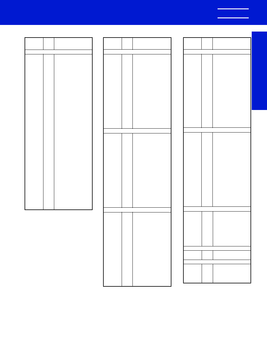
KEMET Electronics Corporation, P.O. Box 5928, Greenville, S.C. 29606, (864) 963-6300
19
Ceramic Molded
Axial/Radial - Standar
d
KEMET
�
CERAMIC MOLDED/RADIAL � STANDARD
STABLE TEMPERATURE CHARACTERISTIC--X7R
TOL.
KEMET
%
PART NUMBER
100 VOLT -- C062 SIZE
12,000
10
C062C123K1R5CA
15,000
10
C062C153K1R5CA
15,000
20
C062C153M1R5CA
18,000
10
C062C183K1R5CA
22,000
10
C062C223K1R5CA
22,000
20
C062C223M1R5CA
27,000
10
C062C273K1R5CA
33,000
10
C062C333K1R5CA
33,000
20
C062C333M1R5CA
39,000
10
C062C393K1R5CA
47,000
10
C062C473K1R5CA
47,000
20
C062C473M1R5CA
56,000
10
C062C563K1R5CA
68,000
10
C062C683K1R5CA
68,000
20
C062C683M1R5CA
82,000
10
C062C823K1R5CA
100,000
10
C062C104K1R5CA
100,000
20
C062C104M1R5CA
50 VOLT -- C062 SIZE
120,000
10
C062C124K5R5CA
150,000
10
C062C154K5R5CA
150,000
20
C062C154M5R5CA
180,000
10
C062C184K5R5CA
220,000
10
C062C224K5R5CA
220,000
20
C062C224M5R5CA
270,000
10
C062C274K5R5CA
330,000
10
C062C334K5R5CA
330,000
20
C062C334M5R5CA
390,000
10
C062C394K5R5CA
470,000
10
C062C474K5R5CA
470,000
20
C062C474M5R5CA
560,000
10
C062C564K5R5CA
680,000
10
C062C684K5R5CA
680,000
20
C062C684M5R5CA
820,000
10
C062C824K5R5CA
1,000,000
10
C062C105K5R5CA
1,000,000
20
C062C105M5R5CA
50 VOLT -- C512 SIZE
1,000,000
10
C512C105K5X5CA
1,000,000
20
C512C105M5X5CA
1,500,000
10
C512C155K5X5CA
1,500,000
20
C512C155M5X5CA
2,000,000
10
C512C205K5X5CA
2,000,000
20
C512C205M5X5CA
2,200,000
10
C512C225K5X5CA
2,200,000
20
C512C225M5X5CA
100 VOLT -- C522 SIZE
1,000,000
10
C522C105K1X5CA
1,000,000
20
C522C105M1X5CA
50 VOLT -- C522 SIZE
2,700,000
10
C522C275K5X5CA
2,700,000
20 C522C275M5X5CA
3,300,000
10
C522C335K5X5CA
3,300,000
20
C522C335M5X5CA
CAPACI�
TANCE
pF
TOL.
KEMET
%
PART NUMBER
100 VOLT -- C052 SIZE
1,200
10
C052C122K1R5CA
1,500
10
C052C152K1R5CA
1,500
20
C052C152M1R5CA
1,800
10
C052C182K1R5CA
2,200
10
C052C222K1R5CA
2,200
20
C052C222M1R5CA
2,700
10
C052C272K1R5CA
3,300
10
C052C332K1R5CA
3,300
20
C052C332M1R5CA
3,900
10
C052C392K1R5CA
4,700
10
C052C472K1R5CA
4,700
20
C052C472M1R5CA
5,600
10
C052C562K1R5CA
6,800
10
C052C682K1R5CA
6,800
20
C052C682M1R5CA
8,200
10
C052C822K1R5CA
10,000
10
C052C103K1R5CA
10,000
20
C052C103M1R5CA
50 VOLT -- C052 SIZE
12,000
10
C052C123K5R5CA
15,000
10
C052C153K5R5CA
15,000
20
C052C153M5R5CA
18,000
10
C052C183K5R5CA
22,000
10
C052C223K5R5CA
22,000
20
C052C223M5R5CA
27,000
10
C052C273K5R5CA
33,000
10
C052C333K5R5CA
33,000
20
C052C333M5R5CA
39,000
10
C052C393K5R5CA
47,000
10
C052C473K5R5CA
47,000
20
C052C473M5R5CA
56,000
10
C052C563K5R5CA
68,000
10
C052C683K5R5CA
68,000
20
C052C683M5R5CA
82,000
10
C052C823K5R5CA
100,000
10
C052C104K5R5CA
100,000
20
C052C104M5R5CA
200 VOLT -- C062 SIZE
1,200
10
C062C122K2R5CA
1,500
10
C062C152K2R5CA
1,500
20
C062C152M2R5CA
1,800
10
C062C182K2R5CA
2,200
10
C062C222K2R5CA
2,200
20
C062C222M2R5CA
2,700
10
C062C272K2R5CA
3,300
10
C062C332K2R5CA
3,300
20
C062C332M2R5CA
3,900
10
C062C392K2R5CA
4,700
10
C062C472K2R5CA
4,700
20
C062C472M2R5CA
5,600
10
C062C562K2R5CA
6,800
10
C062C682K2R5CA
6,800
20
C062C682M2R5CA
8,200
10
C062C822K2R5CA
10,000
10
C062C103K2R5CA
10,000
20
C062C103M2R5CA
RATINGS & PART NUMBER REFERENCE
TOL.
KEMET
%
PART NUMBER
200 VOLT -- C052 SIZE
10
10
C052C100K2R5CA
10
20
C052C100M2R5CA
12
10
C052C120K2R5CA
15
10
C052C150K2R5CA
15
20
C052C150M2R5CA
18
10
C052C180K2R5CA
22
10
C052C220K2R5CA
22
20
C052C220M2R5CA
27
10
C052C270K2R5CA
33
10
C052C330K2R5CA
33
20
C052C330M2R5CA
39
10
C052C390K2R5CA
47
10
C052C470K2R5CA
47
20
C052C470M2R5CA
56
10
C052C560K2R5CA
68
10
C052C680K2R5CA
68
20
C052C680M2R5CA
82
10
C052C820K2R5CA
100
10
C052C101K2R5CA
100
20
C052C101M2R5CA
120
10
C052C121K2R5CA
150
10
C052C151K2R5CA
150
20
C052C151M2R5CA
180
10
C052C181K2R5CA
220
10
C052C221K2R5CA
220
20
C052C221M2R5CA
270
10
C052C271K2R5CA
330
10
C052C331K2R5CA
330
20
C052C331M2R5CA
390
10
C052C391K2R5CA
470
10
C052C471K2R5CA
470
20
C052C471M2R5CA
560
10
C052C561K2R5CA
680
10
C052C681K2R5CA
680
20
C052C681M2R5CA
820
10
C052C821K2R5CA
1,000
10
C052C102K2R5CA
1,000
20
C052C102M2R5CA
CAPACI�
TANCE
pF
CAPACI�
TANCE
pF
0988 Layout rev 8/9/2000 9:54 AM Page 19

CERAMIC MOLDED/AXIAL & RADIAL -- MIL-PRF-20
KEMET Electronics Corporation, P.O. Box 5928, Greenville, S.C. 29606, (864) 963-6300
20
KEMET
�
Lead Dia.
.025
(+.004
-.002)
W
.026
MIN.
H
L
S
W
.045
MAX.
H
1.25
MIN.
L
S
W
H
1.25
MIN.
L
S
W
Center Line of leads within .030" of Center Line of case.
H
1.25
MIN.
S
.026
MIN.
L
C052 (CC05, CCR05)
C056 (CCR05)
C062 (CC06, CCR06), C512 (CC07, CCR07),
C522 (CC08, CCR08)
C066 (CCR06)
Lead Dia.
.025
(+.004
-.002)
Lead Dia.
.025
(+.004
-.002)
Lead Dia.
.025
(+.004
-.002)
1.25
MIN.
DIMENSIONS -- INCHES & (MILLIMETERS)
CASE
MILITARY
SIZE
EQUIVALENT STYLES
L
D
C
C114
CC75, CCR75
.160 � .010 (4.06 � .25)
.090 � .010 (2.29 � .25)
.020, +.000, -.003 (.51, +.00, -.08)
C124
CC76, CCR76
.250 � .010 (6.35 � .25)
.090 � .010 (2.29 � .25)
.020, +.000, -.003 (.51, +.00, -.08)
C192
CC77, CCR77
.390 � .010 (9.91 � .25)
.140 � .010 (3.56 � .25)
.025, +.002, -.002 (.64, +.05, -.05)
C202
CC78, CCR78
.500 � .020 (12.70 � .51)
.250 � .015 (6.35 � .38)
.025, +.002, -.002 (.64, +.05, -.05)
C222
CC79, CCR79
.690 � .030 (17.53 � .76)
.350 � .020 (8.89 � .51)
.025, +.002, -.002 (.64, +.05, -.05)
D
L
C
1.50 Min.
(38.10)
1.50 Min.
(38.10)
CAPACITOR OUTLINE DRAWINGS (AXIAL LEADS)
CAPACITOR OUTLINE DRAWINGS (RADIAL LEADS)
DIMENSIONS -- INCHES & (MILLIMETERS)
MILITARY
S
CASE
EQUIVALENT
H
L
W
LEAD
SIZE
STYLES
HEIGHT
LENGTH
WIDTH
SPACING
CC05, CCR05
.190 � .010 (4.83 � .25)
.190 � .010 (4.83 � .25)
.090 � .010 (2.29 � .25)
.200 � .015 (5.08 � .38)
CC06, CCR06
.290 � .010 (7.37 � .25)
.290 � .010 (7.37 � .25)
.090 � .010 (2.29 � .25)
.200 � .015 (5.08 � .38)
C512
CC07, CCR07
.480 � .020 (12.19 � .51)
.480 � .020 (12.19 � .51)
.140 � .010 (3.56 � .25)*
.400 � .020 (10.16 � .51)
C522
CC08, CCR08
.480 � .020 (12.19 � .51)
.480 � .020 (12.19 � .51)
.240 � .010 (6.10 � .25)
.400 � .020 (10.16 � .51)
C052/
C056
C062/
C066
For packaging information, see pages 32, 33 and 34.
* 0.200 (5.08) maximum for 100,000 pF only.
* Leads are .625 minimum when tape and reel packaged
0988 Layout rev 8/9/2000 9:54 AM Page 20
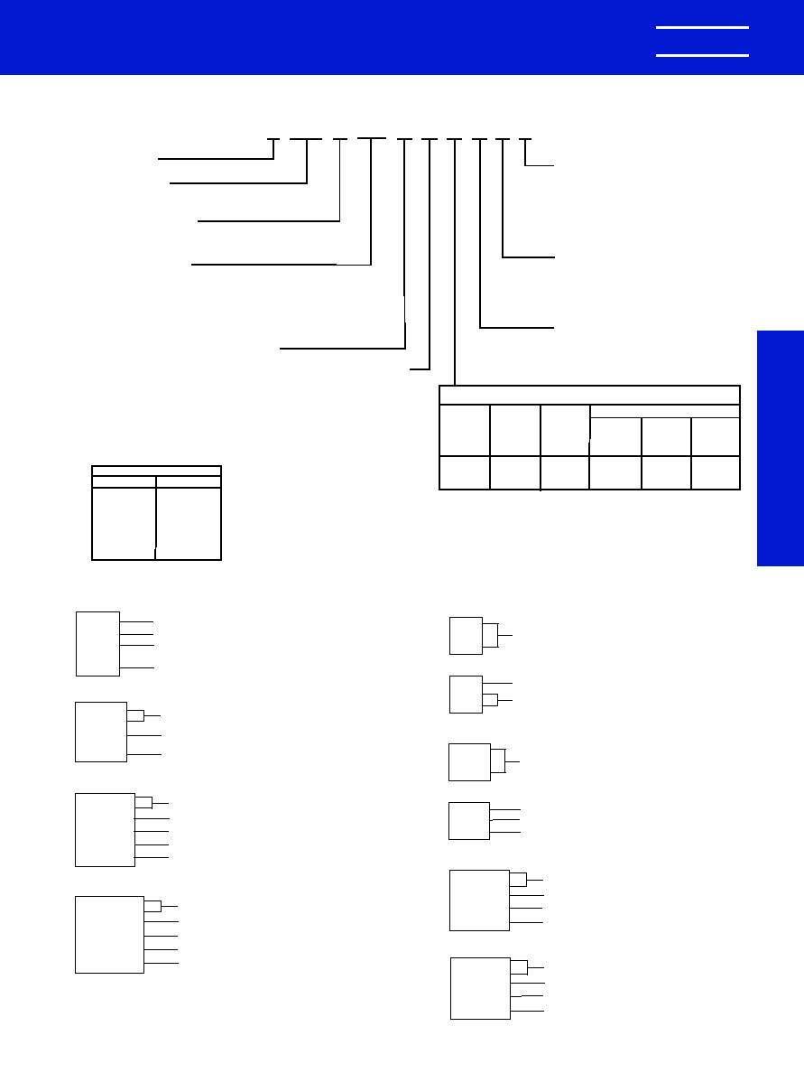
CC(R) 75, 76
KEMET Electronics Corporation, P.O. Box 5928, Greenville, S.C. 29606, (864) 963-6300
21
KEMET
�
CERAMIC MOLDED/AXIAL & RADIAL -- MIL-PRF-20
MIL-PRF-20
TEMPERATURE CHARACTERISTIC
Capacitance Change With Temp.
Measured
Measured
Without
With Bias
KEMET
Military
EIA
Temp.
DC Bias
(Rated
Designator Equivalent
Equivalent
Range,
�
C
Voltage
Voltage)
G
*CG
C0G
-55 to
�
30
�
30
(Ultra
(See below)
(NPO)
+125
ppm/
�
C*
ppm/
�
C*
Stable)
*CASE SIZES
RADIAL
AXIAL
C052
C114
C056
C124
C062
C192
C066
C202
C512
C222
C522
J
102
052
C
5
G
R
G
1
C
CERAMIC
*CASE SIZE
(See Table Below)
SPECIFICATION
Military
G -- MIL-PRF-20
CAPACITANCE
In picofarad code: First two digits are significant
figures and third is number of zeroes following
(except 9 indicates division by 10). Examples:
0.1 F = 100,000 pF = 104 and 9.1 pF = 919.
See tables for Standard Values.
FAILURE RATE
INTERNAL CONSTRUCTION
CAPACITANCE TOLERANCE
Standard
K --
�
10%
J --
�
5%
A -- Not Applicable (Std.)
M -- 1.0%
P -- 0.1%
R -- 0.01%
S -- 0.001%
LEAD MATERIAL
C -- Standard
5 -- Standard
WORKING
VOLTAGE
1 -- 100
2 -- 200
5 --
50
Others
G --
�
2%
C --
�
0.25 pF
F --
�
1%
D --
�
0.5 pF
B --
�
0.1 pF
Standard tolerances for each Series are
shown in the repetitive parts lists.
*CH --
�
60 ppm/
�
C 8.2 pF-18.0 pF.
*CJ --
�
120 ppm/
�
C 4.3 pF-7.5 pF.
*CK --
�
250 ppm/
�
C 2.2 pF-3.9 pF
*CX -- not measurable 0.1 pF-2.0 pF.
**
**Part Number Example: C052G102J1G5CR (14 digits � no spaces)
ORDERING INFORMATION
CAPACITOR MARKINGS
JCK
2R2
CM0
11AK
"J" Brand (CCR only), Temperature Characteristic
Capacitance
Capacitance Tolerance, Failure Rate (CCR only),
Year Code
Lot Code, Trademark (K)
CCR0
5CH1
00FR
FRONT
CC(R) 05
Military Designation (Type, Temperature Characteristic,
Capacitance, Tolerance, Failure Rate)
** For the standoff style, a "V" is added after the
failure rate, or last character.
0004
AJ3
1433
REAR
Date Code
Lot Code, "J" Brand (CCR only),
FSCM (Federal Source Code)
CCR77C
G102JM
J31433
0004A
Military Designation (Type, Temperature Characteristic,
Capacitance, Tolerance, Failure Rate)
"J" Brand (CCR only), FSCM (Federal Source Code)
Date/Lot Code
CC(R) 77
CCR78CG
103FR
JAN K
31433
100V
0004A
Military Designation (Type, Temperature Characteristic,
Capacitance, Tolerance, Failure Rate)
"JAN" Brand (CCR only), Trademark (K)
FSCM (Federal Source Code)
Voltage
Date/Lot Code
CC(R) 78
CCR79CG
103KM
JAN K
31433
200V
0004A
Military Designation (Type, Temperature Characteristic,
Capacitance, Tolerance, Failure Rate)
"JAN" Brand (CCR only), Trademark
FSCM (Federal Source Code)
Voltage
Date/Lot Code
CC(R) 79
CCR06
CG102
JS
FRONT
CC(R) 06
Military Designation (Type, Temperature Characteristic,
Capacitance, Tolerance, Failure Rate)
** For the standoff style, a "V" is added after the
failure rate, or last character.
0004A
J100V
31433
REAR
Date/LotCode
"J" Brand (CCR only), Voltage
FSCM (Federal Source Code)
CCR07CG
472KM
JAN KEMET
31433
200V 0004A
Military Designation (Type, Temperature Characteristic,
Capacitance, Tolerance, Failure Rate)
"JAN" Brand, Trademark
FSCM (Federal Source Code)
Voltage, Date/Lot Code
CC(R) 07
CCR08CG
472KM
JAN KEMET
31433
200V 0009A
Military Designation (Type, Temperature Characteristic,
Capacitance, Tolerance, Failure Rate)
"JAN" Brand, Trademark
FSCM (Federal Source Code)
Voltage, Date/Lot Code
CC(R) 08
0988 Layout rev 8/9/2000 9:54 AM Page 21
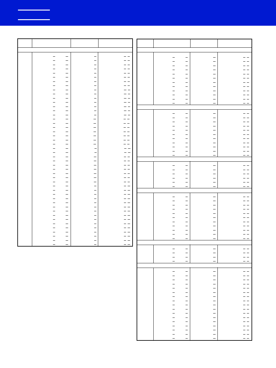
CAP.
KEMET
MILITARY STYLE
MILITARY STYLE
pF
PART NUMBER
CC
CCR
200 VOLT -- C114 (CC(R)75 PER MIL-PRF-20/27)
1.0
C114G109(2)2G5C(1)
CC75CX1R0(2)
CCR75CX1R0(2)(1)
1.1
C114G119(2)2G5C(1)
CC75CX1R1(2)
CCR75CX1R1(2)(1)
1.2
C114G129(2)2G5C(1)
CC75CX1R2(2)
CCR75CX1R2(2)(1)
1.3
C114G139(2)2G5C(1)
CC75CX1R3(2)
CCR75CX1R3(2)(1)
1.5
C114G159(2)2G5C(1)
CC75CX1R5(2)
CCR75CX1R5(2)(1)
1.6
C114G169(2)2G5C(1)
CC75CX1R6(2)
CCR75CX1R6(2)(1)
1.8
C114G189(2)2G5C(1)
CC75CX1R8(2)
CCR75CX1R8(2)(1)
2.0
C114G209(2)2G5C(1)
CC75CX2R0(2)
CCR75CX2R0(2)(1)
2.2
C114G229(2)2G5C(1)
CC75CK2R2(2) CCR75CK2R2(2)(1)
2.4
C114G249(2)2G5C(1)
CC75CK2R4(2) CCR75CK2R4(2)(1)
2.7
C114G279(3)2G5C(1)
CC75CK2R7(3) CCR75CK2R7(3)(1)
3.0
C114G309(3)2G5C(1)
CC75CK3R0(3) CCR75CK3R0(3)(1)
3.3
C114G339(3)2G5C(1)
CC75CK3R3(3) CCR75CK3R3(3)(1)
3.6
C114G369(3)2G5C(1)
CC75CK3R6(3) CCR75CK3R6(3)(1)
3.9
C114G399(3)2G5C(1)
CC75CK3R9(3) CCR75CK3R9(3)(1)
4.3
C114G439(3)2G5C(1)
CC75CJ4R3(3)
CCR75CJ4R3(3)(1)
4.7
C114G479(3)2G5C(1)
CC75CJ4R7(3)
CCR75CJ4R7(3)(1)
5.1
C114G519(3)2G5C(1)
CC75CJ5R1(3)
CCR75CJ5R1(3)(1)
5.6
C114G569(3)2G5C(1)
CC75CJ5R6(3)
CCR75CJ5R6(3)(1)
6.2
C114G629(3)2G5C(1)
CC75CJ6R2(3)
CCR75CJ6R2(3)(1)
6.8
C114G689(3)2G5C(1)
CC75CJ6R8(3)
CCR75CJ6R8(3)(1)
7.5
C114G759(3)2G5C(1)
CC75CJ7R5(3)
CCR75CJ7R5(3)(1)
8.2
C114G829(3)2G5C(1)
CC75CH8R2(3) CCR75CH8R2(3)(1)
9.1
C114G919(3)2G5C(1)
CC75CH9R1(3) CCR75CH9R1(3)(1)
10.0
C114G100(4)2G5C(1)
CC75CH100(4)
CCR75CH100(4)(1)
11.0
C114G110(4)2G5C(1)
CC75CH110(4)
CCR75CH110(4)(1)
12.0
C114G120(4)2G5C(1)
CC75CH120(4)
CCR75CH120(4)(1)
13.0
C114G130(4)2G5C(1)
CC75CH130(4)
CCR75CH130(4)(1)
15.0
C114G150(4)2G5C(1)
CC75CH150(4)
CCR75CH150(4)(1)
16.0
C114G160(4)2G5C(1)
CC75CH160(4)
CCR75CH160(4)(1)
18.0
C114G180(4)2G5C(1)
CC75CH180(4)
CCR75CH180(4)(1)
20.0
C114G200(4)2G5C(1)
CC75CG200(4)
CCR75CG200(4)(1)
22.0
C114G220(4)2G5C(1)
CC75CG220(4)
CCR75CG220(4)(1)
24.0
C114G240(4)2G5C(1)
CC75CG240(4)
CCR75CG240(4)(1)
27.0
C114G270(4)2G5C(1)
CC75CG270(4)
CCR75CG270(4)(1)
30.0
C114G300(4)2G5C(1)
CC75CG300(4)
CCR75CG300(4)(1)
33.0
C114G330(4)2G5C(1)
CC75CG330(4)
CCR75CG330(4)(1)
36.0
C114G360(4)2G5C(1)
CC75CG360(4)
CCR75CG360(4)(1)
39.0
C114G390(4)2G5C(1)
CC75CG390(4)
CCR75CG390(4)(1)
43.0
C114G430(4)2G5C(1)
CC75CG430(4)
CCR75CG430(4)(1)
47.0
C114G470(4)2G5C(1)
CC75CG470(4)
CCR75CG470(4)(1)
51.0
C114G510(4)2G5C(1)
CC75CG510(4)
CCR75CG510(4)(1)
56.0
C114G560(4)2G5C(1)
CC75CG560(4)
CCR75CG560(4)(1)
62.0
C114G620(4)2G5C(1)
CC75CG620(4)
CCR75CG620(4)(1)
68.0
C114G680(4)2G5C(1)
CC75CG680(4)
CCR75CG680(4)(1)
75.0
C114G750(4)2G5C(1)
CC75CG750(4)
CCR75CG750(4)(1)
CERAMIC MOLDED/AXIAL -- MIL-PRF-20
ULTRA-STABLE TEMPERATURE CHARACTERISTIC -- CG (EIA-C0G)
KEMET Electronics Corporation, P.O. Box 5928, Greenville, S.C. 29606, (864) 963-6300
22
KEMET
�
RATINGS & PART NUMBER REFERENCE
To complete Part Number, insert the following letters:
(1) Available Failure Rates: A (CC styles only); M, P, R & S (CCR styles only).
(2) Available Capacitance Tolerances: B, C.
(3) Available Capacitance Tolerances: B, C, D.
(4) Available Capacitance Tolerances: F, G, J.
CAP.
KEMET
MILITARY STYLE
MILITARY STYLE
pF
PART NUMBER
CC
CCR
100 VOLT -- C114 (CC(R)75 PER MIL-PRF-20/27)
82.0
C114G820(4)1G5C(1)
CC75CG820(4)
CCR75CG820(4)(1)
91.0
C114G910(4)1G5C(1)
CC75CG910(4)
CCR75CG910(4)(1)
100.0
C114G101(4)1G5C(1)
CC75CG101(4)
CCR75CG101(4)(1)
110.0
C114G111(4)1G5C(1)
CC75CG111(4)
CCR75CG111(4)(1)
120.0
C114G121(4)1G5C(1)
CC75CG121(4)
CCR75CG121(4)(1)
130.0
C114G131(4)1G5C(1)
CC75CG131(4)
CCR75CG131(4)(1)
150.0
C114G151(4)1G5C(1)
CC75CG151(4)
CCR75CG151(4)(1)
160.0
C114G161(4)1G5C(1)
CC75CG161(4)
CCR75CG161(4)(1)
180.0
C114G181(4)1G5C(1)
CC75CG181(4)
CCR75CG181(4)(1)
200.0
C114G201(4)1G5C(1)
CC75CG201(4)
CCR75CG201(4)(1)
220.0
C114G221(4)1G5C(1)
CC75CG221(4)
CCR75CG221(4)(1)
240.0
C114G241(4)1G5C(1)
CC75CG241(4)
CCR75CG241(4)(1)
50 VOLT -- C114 (CC(R)75 PER MIL-PRF-20/27)
270.0
C114G271(4)5G5C(1)
CC75CG271(4)
CCR75CG271(4)(1)
300.0
C114G301(4)5G5C(1)
CC75CG301(4)
CCR75CG301(4)(1)
330.0
C114G331(4)5G5C(1)
CC75CG331(4)
CCR75CG331(4)(1)
360.0
C114G361(4)5G5C(1)
CC75CG361(4)
CCR75CG361(4)(1)
390.0
C114G391(4)5G5C(1)
CC75CG391(4)
CCR75CG391(4)(1)
430.0
C114G431(4)5G5C(1)
CC75CG431(4)
CCR75CG431(4)(1)
470.0
C114G471(4)5G5C(1)
CC75CG471(4)
CCR75CG471(4)(1)
510.0
C114G511(4)5G5C(1)
CC75CG511(4)
CCR75CG511(4)(1)
560.0
C114G561(4)5G5C(1)
CC75CG561(4)
CCR75CG561(4)(1)
620.0
C114G621(4)5G5C(1)
CC75CG621(4)
CCR75CG621(4)(1)
680.0
C114G681(4)5G5C(1)
CC75CG681(4)
CCR75CG681(4)(1)
200 VOLT -- C124 (CC(R)76 PER MIL-PRF-20/28)
82.0
C124G820(4)2G5C(1)
CC76CG820(4)
CCR76CG820(4)(1)
91.0
C124G910(4)2G5C(1)
CC76CG910(4)
CCR76CG910(4)(1)
100.0
C124G101(4)2G5C(1)
CC76CG101(4)
CCR76CG101(4)(1)
110.0
C124G111(4)2G5C(1)
CC76CG111(4)
CCR76CG111(4)(1)
120.0
C124G121(4)2G5C(1)
CC76CG121(4)
CCR76CG121(4)(1)
130.0
C124G131(4)2G5C(1)
CC76CG131(4)
CCR76CG131(4)(1)
100 VOLT -- C124 (CC(R)76 PER MIL-PRF-20/28)
270.0
C124G271(4)1G5C(1)
CC76CG271(4)
CCR76CG271(4)(1)
300.0
C124G301(4)1G5C(1)
CC76CG301(4)
CCR76CG301(4)(1)
330.0
C124G331(4)1G5C(1)
CC76CG331(4)
CCR76CG331(4)(1)
360.0
C124G361(4)1G5C(1)
CC76CG361(4)
CCR76CG361(4)(1)
390.0
C124G391(4)1G5C(1)
CC76CG391(4)
CCR76CG391(4)(1)
430.0
C124G431(4)1G5C(1)
CC76CG431(4)
CCR76CG431(4)(1)
470.0
C124G471(4)1G5C(1)
CC76CG471(4)
CCR76CG471(4)(1)
510.0
C124G511(4)1G5C(1)
CC76CG511(4)
CCR76CG511(4)(1)
560.0
C124G561(4)1G5C(1)
CC76CG561(4)
CCR76CG561(4)(1)
620.0
C124G621(4)1G5C(1)
CC76CG621(4)
CCR76CG621(4)(1)
680.0
C124G681(4)1G5C(1)
CC76CG681(4)
CCR76CG681(4)(1)
50 VOLT -- C124 (CC(R)76 PER MIL-PRF-20/28)
750.0
C124G751(4)5G5C(1)
CC76CG751(4)
CCR76CG751(4)(1)
820.0
C124G821(4)5G5C(1)
CC76CG821(4)
CCR76CG821(4)(1)
910.0
C124G911(4)5G5C(1)
CC76CG911(4)
CCR76CG911(4)(1)
1,000.0
C124G102(4)5G5C(1)
CC76CG102(4)
CCR76CG102(4)(1)
200 VOLT -- C192 (CC(R)77 PER MIL-PRF-20/29)
150.0
C192G151(4)2G5C(1)
CC77CG151(4)
CCR77CG151(4)(1)
160.0
C192G161(4)2G5C(1)
CC77CG161(4)
CCR77CG161(4)(1)
180.0
C192G181(4)2G5C(1)
CC77CG181(4)
CCR77CG181(4)(1)
200.0
C192G201(4)2G5C(1)
CC77CG201(4)
CCR77CG201(4)(1)
220.0
C192G221(4)2G5C(1)
CC77CG221(4)
CCR77CG221(4)(1)
240.0
C192G241(4)2G5C(1)
CC77CG241(4)
CCR77CG241(4)(1)
270.0
C192G271(4)2G5C(1)
CC77CG271(4)
CCR77CG271(4)(1)
300.0
C192G301(4)2G5C(1)
CC77CG301(4)
CCR77CG301(4)(1)
330.0
C192G331(4)2G5C(1)
CC77CG331(4)
CCR77CG331(4)(1)
360.0
C192G361(4)2G5C(1)
CC77CG361(4)
CCR77CG361(4)(1)
390.0
C192G391(4)2G5C(1)
CC77CG391(4)
CCR77CG391(4)(1)
430.0
C192G431(4)2G5C(1)
CC77CG431(4)
CCR77CG431(4)(1)
470.0
C192G471(4)2G5C(1)
CC77CG471(4)
CCR77CG471(4)(1)
510.0
C192G511(4)2G5C(1)
CC77CG511(4)
CCR77CG511(4)(1)
560.0
C192G561(4)2G5C(1)
CC77CG561(4)
CCR77CG561(4)(1)
620.0
C192G621(4)2G5C(1)
CC77CG621(4)
CCR77CG621(4)(1)
680.0
C192G681(4)2G5C(1)
CC77CG681(4)
CCR77CG681(4)(1)
0988 Layout rev 8/9/2000 9:54 AM Page 22
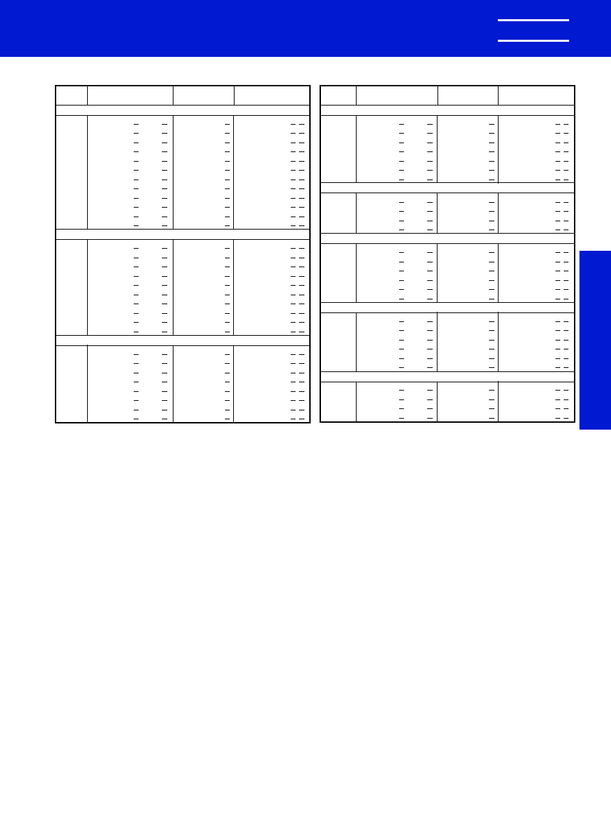
KEMET Electronics Corporation, P.O. Box 5928, Greenville, S.C. 29606, (864) 963-6300
23
KEMET
�
CERAMIC MOLDED/AXIAL -- MIL-PRF-20
ULTRA-STABLE TEMPERATURE CHARACTERISTIC -- CG (EIA-C0G)
MIL-PRF-20
CAP.
KEMET
MILITARY STYLE
MILITARY STYLE
pF
PART NUMBER
CC
CCR
100 VOLT -- C192 (CC(R)77 PER MIL-PRF-20/29)
750.0
C192G751(4)1G5C(1)
CC77CG751(4)
CCR77CG751(4)(1)
820.0
C192G821(4)1G5C(1)
CC77CG821(4)
CCR77CG821(4)(1)
910.0
C192G911(4)1G5C(1)
CC77CG911(4)
CCR77CG911(4)(1)
1,000.0
C192G102(4)1G5C(1)
CC77CG102(4)
CCR77CG102(4)(1)
1,100.0
C192G112(4)1G5C(1)
CC77CG112(4)
CCR77CG112(4)(1)
1,200.0
C192G122(4)1G5C(1)
CC77CG122(4)
CCR77CG122(4)(1)
1,300.0
C192G132(4)1G5C(1)
CC77CG132(4)
CCR77CG132(4)(1)
1,500.0
C192G152(4)1G5C(1)
CC77CG152(4)
CCR77CG152(4)(1)
1,600.0
C192G162(4)1G5C(1)
CC77CG162(4)
CCR77CG162(4)(1)
1,800.0
C192G182(4)1G5C(1)
CC77CG182(4)
CCR77CG182(4)(1)
2,000.0
C192G202(4)1G5C(1)
CC77CG202(4)
CCR77CG202(4)(1)
2,200.0
C192G222(4)1G5C(1)
CC77CG222(4)
CCR77CG222(4)(1)
50 VOLT -- C192 (CC(R)77 PER MIL-PRF-20/29)
2,400.0
C192G242(4)5G5C(1)
CC77CG242(4)
CCR77CG242(4)(1)
2,700.0
C192G272(4)5G5C(1)
CC77CG272(4)
CCR77CG272(4)(1)
3,000.0
C192G302(4)5G5C(1)
CC77CG302(4)
CCR77CG302(4)(1)
3,300.0
C192G332(4)5G5C(1)
CC77CG332(4)
CCR77CG332(4)(1)
3,600.0
C192G362(4)5G5C(1)
CC77CG362(4)
CCR77CG362(4)(1)
3,900.0
C192G392(4)5G5C(1)
CC77CG392(4)
CCR77CG392(4)(1)
4,300.0
C192G432(4)5G5C(1)
CC77CG432(4)
CCR77CG432(4)(1)
4,700.0
C192G472(4)5G5C(1)
CC77CG472(4)
CCR77CG472(4)(1)
5,100.0
C192G512(5)5G5C(1)
CC77CG512(5)
CCR77CG512(5)(1)
5,600.0
C192G562(5)5G5C(1)
CC77CG562(5)
CCR77CG562(5)(1)
200 VOLT -- C202 (CC(R)78 PER MIL-PRF-20/30)
820.0
C202G821(5)2G5C(1)
CC78CG821(5)
CCR78CG821(5)(1)
1,000.0
C202G102(5)2G5C(1)
CC78CG102(5)
CCR78CG102(5)(1)
1,200.0
C202G122(5)2G5C(1)
CC78CG122(5)
CCR78CG122(5)(1)
1,500.0
C202G152(5)2G5C(1)
CC78CG152(5)
CCR78CG152(5)(1)
1,800.0
C202G182(5)2G5C(1)
CC78CG182(5)
CCR78CG182(5)(1)
2,200.0
C202G222(5)2G5C(1)
CC78CG222(5)
CCR78CG222(5)(1)
2,700.0
C202G272(5)2G5C(1)
CC78CG272(5)
CCR78CG272(5)(1)
3,300.0
C202G332(5)2G5C(1)
CC78CG332(5)
CCR78CG332(5)(1)
RATINGS & PART NUMBER REFERENCE
To complete Part Number, insert the following letters:
(1) Available Failure Rates: A (CC styles only); M, P, R & S (CCR styles only).
(2) Available Capacitance Tolerances: B, C.
(3) Available Capacitance Tolerances: B, C, D.
(4) Available Capacitance Tolerances: F, G, J.
(5) Available Capacitance Tolerances: F, G, J, K.
CAP.
KEMET
MILITARY STYLE
MILITARY STYLE
pF
PART NUMBER
CC
CCR
100 VOLT -- C202 (CC(R)78 PER MIL-PRF-20/30)
3,900.0 C202G392(5)1G5C(1)
CC78CG392(5)
CCR78CG392(5)(1)
4,700.0 C202G472(5)1G5C(1)
CC78CG472(5)
CCR78CG472(5)(1)
5,600.0 C202G562(5)1G5C(1)
CC78CG562(5)
CCR78CG562(5)(1)
6,800.0 C202G682(5)1G5C(1)
CC78CG682(5)
CCR78CG682(5)(1)
8,200.0 C202G822(5)1G5C(1)
CC78CG822(5)
CCR78CG822(5)(1)
10,000.0 C202G103(5)1G5C(1)
CC78CG103(5)
CCR78CG103(5)(1)
12,000.0 C202G123(5)1G5C(1)
CC78CG123(5)
CCR78CG123(5)(1)
50 VOLT -- C202 (CC(R)78 PER MIL-PRF-20/30)
15,000.0 C202G153(5)5G5C(1)
CC78CG153(5)
CCR78CG153(5)(1)
18,000.0 C202G183(5)5G5C(1)
CC78CG183(5)
CCR78CG183(5)(1)
22,000.0 C202G223(5)5G5C(1)
CC78CG223(5)
CCR78CG223(5)(1)
27,000.0 C202G273(5)5G5C(1)
CC78CG273(5)
CCR78CG273(5)(1)
200 VOLT -- C222 (CC(R)79 PER MIL-PRF-20/31)
3,900.0 C222G392(5)2G5C(1)
CC79CG392(5)
CCR79CG392(5)(1)
4,700.0 C222G472(5)2G5C(1)
CC79CG472(5)
CCR79CG472(5)(1)
5,600.0 C222G562(5)2G5C(1)
CC79CG562(5)
CCR79CG562(5)(1)
6,800.0 C222G682(5)2G5C(1)
CC79CG682(5)
CCR79CG682(5)(1)
8,200.0 C222G822(5)2G5C(1)
CC79CG822(5)
CCR79CG822(5)(1)
10,000.0 C222G103(5)2G5C(1)
CC79CG103(5)
CCR79CG103(5)(1)
100 VOLT -- C222 (CC(R)79 PER MIL-PRF-20/31)
15,000.0 C222G153(5)1G5C(1)
CC79CG153(5)
CCR79CG153(5)(1)
18,000.0 C222G183(5)1G5C(1)
CC79CG183(5)
CCR79CG183(5)(1)
22,000.0 C222G223(5)1G5C(1)
CC79CG223(5)
CCR79CG223(5)(1)
27,000.0 C222G273(5)1G5C(1)
CC79CG273(5)
CCR79CG273(5)(1)
33,000.0 C222G333(5)1G5C(1)
CC79CG333(5)
CCR79CG333(5)(1)
39,000.0 C222G393(5)1G5C(1)
CC79CG393(5)
CCR79CG393(5)(1)
50 VOLT -- C222 (CC(R)79 PER MIL-PRF-20/31)
47,000.0 C222G473(5)5G5C(1)
CC79CG473(5)
CCR79CG473(5)(1)
56,000.0 C222G563(5)5G5C(1)
CC79CG563(5)
CCR79CG563(5)(1)
68,000.0 C222G683(5)5G5C(1)
CC79CG683(5)
CCR79CG683(5)(1)
82,000.0 C222G823(5)5G5C(1)
CC79CG823(5)
CCR79CG823(5)(1)
0988 Layout rev 8/9/2000 9:54 AM Page 23
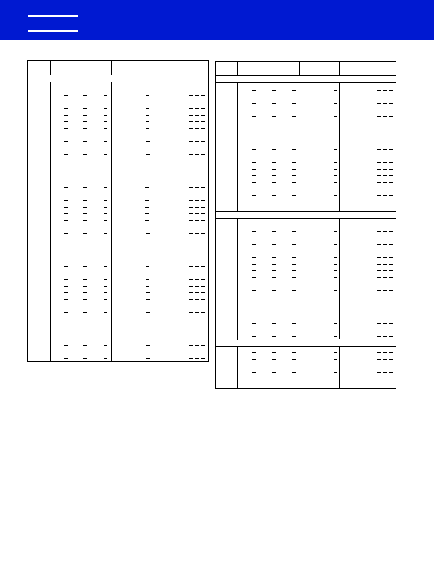
CERAMIC MOLDED/RADIAL -- MIL-PRF-20
ULTRA-STABLE TEMPERATURE CHARACTERISTIC -- CG (EIA-C0G)
KEMET Electronics Corporation, P.O. Box 5928, Greenville, S.C. 29606, (864) 963-6300
24
KEMET
�
CAP.
KEMET
MILITARY STYLE
MILITARY STYLE
pF
PART NUMBER
CC
CCR
200 VOLT -- C052/C056 SIZE (CC(R)05 PER MIL-PRF-20/35)
1.0
C05(6)G109(2)2G5C(1) CC05CX1R0(2) CCR05CX1R0(2)(1)(7)
1.1
C05(6)G119(2)2G5C(1) CC05CX1R1(2) CCR05CX1R1(2)(1)(7)
1.2
C05(6)G129(2)2G5C(1) CC05CX1R2(2) CCR05CX1R2(2)(1)(7)
1.3
C05(6)G139(2)2G5C(1) CC05CX1R3(2) CCR05CX1R3(2)(1)(7)
1.5
C05(6)G159(2)2G5C(1) CC05CX1R5(2) CCR05CX1R5(2)(1)(7)
1.6
C05(6)G169(2)2G5C(1) CC05CX1R6(2) CCR05CX1R6(2)(1)(7)
1.8
C05(6)G189(2)2G5C(1) CC05CX1R8(2) CCR05CX1R8(2)(1)(7)
2.0
C05(6)G209(2)2G5C(1) CC05CX2R0(2) CCR05CX2R0(2)(1)(7)
2.2
C05(6)G229(2)2G5C(1) CC05CK2R2(2) CCR05CK2R2(2)(1)(7)
2.4
C05(6)G249(2)2G5C(1) CC05CK2R4(2) CCR05CK2R4(2)(1)(7)
2.7
C05(6)G279(3)2G5C(1) CC05CK2R7(3) CCR05CK2R7(3)(1)(7)
3.0
C05(6)G309(3)2G5C(1) CC05CK3R0(3) CCR05CK3R0(3)(1)(7)
3.3
C05(6)G339(3)2G5C(1) CC05CK3R3(3) CCR05CK3R3(3)(1)(7)
3.6
C05(6)G369(3)2G5C(1) CC05CK3R6(3) CCR05CK3R6(3)(1)(7)
3.9
C05(6)G399(3)2G5C(1) CC05CK3R9(3) CCR05CK3R9(3)(1)(7)
4.3
C05(6)G439(3)2G5C(1) CC05CJ4R3(3) CCR05CJ4R3(3)(1)(7)
4.7
C05(6)G479(3)2G5C(1) CC05CJ4R7(3) CCR05CJ4R7(3)(1)(7)
5.1
C05(6)G519(3)2G5C(1) CC05CJ5R1(3) CCR05CJ5R1(3)(1)(7)
5.6
C05(6)G569(3)2G5C(1) CC05CJ5R6(3) CCR05CJ5R6(3)(1)(7)
6.2
C05(6)G629(3)2G5C(1) CC05CJ6R2(3) CCR05CJ6R2(3)(1)(7)
6.8
C05(6)G689(3)2G5C(1) CC05CJ6R8(3) CCR05CJ6R8(3)(1)(7)
7.5
C05(6)G759(3)2G5C(1) CC05CJ7R5(3) CCR05CJ7R5(3)(1)(7)
8.2
C05(6)G829(3)2G5C(1) CC05CH8R2(3) CCR05CH8R2(3)(1)(7)
9.1
C05(6)G919(3)2G5C(1) CC05CH9R1(3) CCR05CH9R1(3)(1)(7)
10.0
C05(6)G100(4)2G5C(1) CC05CH100(4) CCR05CH100(4)(1)(7)
11.0
C05(6)G110(4)2G5C(1) CC05CH110(4) CCR05CH110(4)(1)(7)
12.0
C05(6)G120(4)2G5C(1) CC05CH120(4) CCR05CH120(4)(1)(7)
13.0
C05(6)G130(4)2G5C(1) CC05CH130(4) CCR05CH130(4)(1)(7)
15.0
C05(6)G150(4)2G5C(1) CC05CH150(4) CCR05CH150(4)(1)(7)
16.0
C05(6)G160(4)2G5C(1) CC05CH160(4) CCR05CH160(4)(1)(7)
18.0
C05(6)G180(4)2G5C(1) CC05CH180(4) CCR05CH180(4)(1)(7)
20.0
C05(6)G200(4)2G5C(1) CC05CG200(4) CCR05CG200(4)(1)(7)
22.0
C05(6)G220(4)2G5C(1) CC05CG220(4) CCR05CG220(4)(1)(7)
24.0
C05(6)G240(4)2G5C(1) CC05CG240(4) CCR05CG240(4)(1)(7)
27.0
C05(6)G270(4)2G5C(1) CC05CG270(4) CCR05CG270(4)(1)(7)
30.0
C05(6)G300(4)2G5C(1) CC05CG300(4) CCR05CG300(4)(1)(7)
33.0
C05(6)G330(4)2G5C(1) CC05CG330(4) CCR05CG330(4)(1)(7)
36.0
C05(6)G360(4)2G5C(1) CC05CG360(4) CCR05CG360(4)(1)(7)
39.0
C05(6)G390(4)2G5C(1) CC05CG390(4) CCR05CG390(4)(1)(7)
43.0
C05(6)G430(4)2G5C(1) CC05CG430(4) CCR05CG430(4)(1)(7)
47.0
C05(6)G470(4)2G5C(1) CC05CG470(4) CCR05CG470(4)(1)(7)
51.0
C05(6)G510(4)2G5C(1) CC05CG510(4) CCR05CG510(4)(1)(7)
RATINGS & PART NUMBER REFERENCE
To complete Part Number, insert the following letters:
(1) Available Failure Rates: A (CC styles only); M, P, R & S (CCR styles only).
(2) Available Capacitance Tolerances: B, C.
(3) Available Capacitance Tolerances: B, C, D.
(4) Available Capacitance Tolerances: F, G, J.
(5) Available Capacitance Tolerances: F, G, J, K.
(6) Insert "2" for standard design, Style C052G
Stand-offs are available
Insert "6" for stand-off design, Style C056G
only as CCR's, not available as CC.
(7) Add "V" for stand-off design, Style C056G
And leave blank for the flat bottom design (C052G)
CAP.
KEMET
MILITARY STYLE
MILITARY STYLE
pF
PART NUMBER
CC
CCR
200 VOLT -- C052/C056 SIZE (CC(R)05 PER MIL-PRF-20/35)
56.0
C05(6)G560(4)2G5C(1) CC05CG560(4) CCR05CG560(4)(1)(7)
62.0
C05(6)G620(4)2G5C(1) CC05CG620(4) CCR05CG620(4)(1)(7)
68.0
C05(6)G680(4)2G5C(1) CC05CG680(4) CCR05CG680(4)(1)(7)
75.0
C05(6)G750(4)2G5C(1) CC05CG750(4) CCR05CG750(4)(1)(7)
82.0
C05(6)G820(4)2G5C(1) CC05CG820(4) CCR75CG820(4)(1)(7)
91.0
C05(6)G910(4)2G5C(1) CC05CG910(4) CCR05CG910(4)(1)(7)
100.0
C05(6)G101(4)2G5C(1) CC05CG101(4) CCR05CG101(4)(1)(7)
110.0
C05(6)G111(4)2G5C(1) CC05CG111(4) CCR05CG111(4)(1)(7)
120.0
C05(6)G121(4)2G5C(1) CC05CG121(4) CCR05CG121(4)(1)(7)
130.0
C05(6)G131(4)2G5C(1) CC05CG131(4) CCR05CG131(4)(1)(7)
150.0
C05(6)G151(4)2G5C(1) CC05CG151(4) CCR05CG151(4)(1)(7)
160.0
C05(6)G161(4)2G5C(1) CC05CG161(4) CCR05CG161(4)(1)(7)
180.0
C05(6)G181(4)2G5C(1) CC05CG181(4) CCR05CG181(4)(1)(7)
200.0
C05(6)G201(4)2G5C(1) CC05CG201(4) CCR05CG201(4)(1)(7)
220.0
C05(6)G221(4)2G5C(1) CC05CG221(4) CCR05CG221(4)(1)(7)
240.0
C05(6)G241(4)2G5C(1) CC05CG241(4) CCR05CG241(4)(1)(7)
270.0
C05(6)G271(4)2G5C(1) CC05CG271(4) CCR05CG271(4)(1)(7)
300.0
C05(6)G301(4)2G5C(1) CC05CG301(4) CCR05CG301(4)(1)(7)
330.0
C05(6)G331(4)2G5C(1) CC05CG331(4) CCR05CG331(4)(1)(7)
100 VOLT -- C052/C056 SIZE (CC(R)05 PER MIL-PRF-20/35)
360.0
C05(6)G361(4)1G5C(1) CC05CG361(4) CCR05CG361(4)(1)(7)
390.0
C05(6)G391(4)1G5C(1) CC05CG391(4) CCR05CG391(4)(1)(7)
430.0
C05(6)G431(4)1G5C(1) CC05CG431(4) CCR05CG431(4)(1)(7)
470.0
C05(6)G471(4)1G5C(1) CC05CG471(4) CCR05CG471(4)(1)(7)
510.0
C05(6)G511(4)1G5C(1) CC05CG511(4) CCR05CG511(4)(1)(7)
560.0
C05(6)G561(4)1G5C(1) CC05CG561(4) CCR05CG561(4)(1)(7)
620.0
C05(6)G621(4)1G5C(1) CC05CG621(4) CCR05CG621(4)(1)(7)
680.0
C05(6)G681(4)1G5C(1) CC05CG681(4) CCR05CG681(4)(1)(7)
750.0
C05(6)G751(4)1G5C(1) CC05CG751(4) CCR05CG751(4)(1)(7)
820.0
C05(6)G821(4)1G5C(1) CC05CG821(4) CCR05CG821(4)(1)(7)
910.0
C05(6)G911(4)1G5C(1) CC05CG911(4) CCR05CG911(4)(1)(7)
1,000.0 C05(6)G102(4)1G5C(1) CC05CG102(4) CCR05CG102(4)(1)(7)
1,100.0 C05(6)G112(4)1G5C(1) CC05CG112(4) CCR05CG112(4)(1)(7)
1,200.0 C05(6)G122(4)1G5C(1) CC05CG122(4) CCR05CG122(4)(1)(7)
1,300.0 C05(6)G132(4)1G5C(1) CC05CG132(4) CCR05CG132(4)(1)(7)
1,500.0 C05(6)G152(4)1G5C(1) CC05CG152(4) CCR05CG152(4)(1)(7)
1,600.0 C05(6)G162(4)1G5C(1) CC05CG162(4) CCR05CG162(4)(1)(7)
1,800.0 C05(6)G182(4)1G5C(1) CC05CG182(4) CCR05CG182(4)(1)(7)
50 VOLT -- C052/C056 SIZE (CC(R)05 PER MIL-PRF-20/35)
2,000.0 C05(6)G202(4)5G5C(1) CC05CG202(4) CCR05CG202(4)(1)(7)
2,200.0 C05(6)G222(4)5G5C(1) CC05CG222(4) CCR05CG222(4)(1)(7)
2,400.0 C05(6)G242(4)5G5C(1) CC05CG242(4) CCR05CG242(4)(1)(7)
2,700.0 C05(6)G272(4)5G5C(1) CC05CG272(4) CCR05CG272(4)(1)(7)
3,000.0 C05(6)G302(4)5G5C(1) CC05CG302(4) CCR05CG302(4)(1)(7)
3,300.0 C05(6)G332(4)5G5C(1) CC05CG332(4) CCR05CG332(4)(1)(7)
}
0988 Layout rev 8/9/2000 9:54 AM Page 24
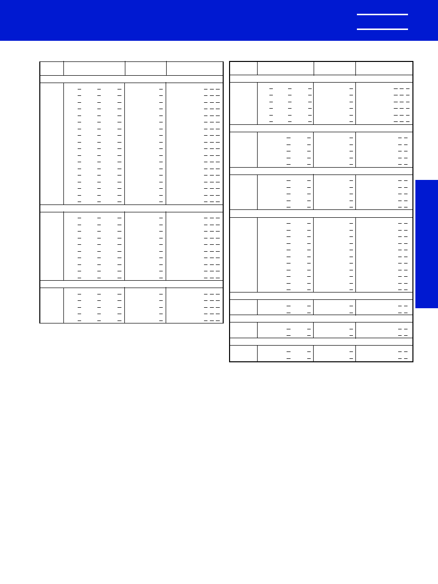
KEMET Electronics Corporation, P.O. Box 5928, Greenville, S.C. 29606, (864) 963-6300
25
KEMET
�
CERAMIC MOLDED/RADIAL -- MIL-PRF-20
ULTRA-STABLE TEMPERATURE CHARACTERISTIC -- CG (EIA-C0G)
MIL-PRF-20
CAP.
KEMET
MILITARY STYLE
MILITARY STYLE
pF
PART NUMBER
CC
CCR
200 VOLT -- C062/C066 SIZE (CC(R)06 PER MIL-PRF-20/36)
360.0 C06(6)G361(4)2G5C(1) CC06CG361(4) CCR06CG361(4)(1)(7)
390.0 C06(6)G391(4)2G5C(1) CC06CG391(4) CCR06CG391(4)(1)(7)
430.0 C06(6)G431(4)2G5C(1) CC06CG431(4) CCR06CG431(4)(1)(7)
470.0 C06(6)G471(4)2G5C(1) CC06CG471(4) CCR06CG471(4)(1)(7)
510.0 C06(6)G511(4)2G5C(1) CC06CG511(4) CCR06CG511(4)(1)(7)
560.0 C06(6)G561(4)2G5C(1) CC06CG561(4) CCR06CG561(4)(1)(7)
620.0 C06(6)G621(4)2G5C(1) CC06CG621(4) CCR06CG621(4)(1)(7)
680.0 C06(6)G681(4)2G5C(1) CC06CG681(4) CCR06CG681(4)(1)(7)
750.0 C06(6)G751(4)2G5C(1) CC06CG751(4) CCR06CG751(4)(1)(7)
820.0 C06(6)G821(4)2G5C(1) CC06CG821(4) CCR06CG821(4)(1)(7)
910.0 C06(6)G911(4)2G5C(1) CC06CG911(4) CCR06CG911(4)(1)(7)
1,000.0 C06(6)G102(4)2G5C(1) CC06CG102(4) CCR06CG102(4)(1)(7)
1,100.0 C06(6)G112(4)2G5C(1) CC06CG112(4) CCR06CG112(4)(1)(7)
1,200.0 C06(6)G122(4)2G5C(1) CC06CG122(4) CCR06CG122(4)(1)(7)
1,300.0 C06(6)G132(4)2G5C(1) CC06CG132(4) CCR06CG132(4)(1)(7)
1,500.0 C06(6)G152(4)2G5C(1) CC06CG152(4) CCR06CG152(4)(1)(7)
1,600.0 C06(6)G162(4)2G5C(1) CC06CG162(4) CCR06CG162(4)(1)(7)
1,800.0 C06(6)G182(4)2G5C(1) CC06CG182(4) CCR06CG182(4)(1)(7)
100 VOLT -- C062/C066 SIZE (CC(R)06 PER MIL-PRF-20/36)
2,000.0 C06(6)G202(4)1G5C(1) CC06CG202(4) CCR06CG202(4)(1)(7)
2,200.0 C06(6)G222(4)1G5C(1) CC06CG222(4) CCR06CG222(4)(1)(7)
2,400.0 C06(6)G242(4)1G5C(1) CC06CG242(4) CCR06CG242(4)(1)(7)
2,700.0 C06(6)G272(4)1G5C(1) CC06CG272(4) CCR06CG272(4)(1)(7)
3,000.0 C06(6)G302(4)1G5C(1) CC06CG302(4) CCR06CG302(4)(1)(7)
3,300.0 C06(6)G332(4)1G5C(1) CC06CG332(4) CCR06CG332(4)(1)(7)
3,600.0 C06(6)G362(4)1G5C(1) CC06CG362(4) CCR06CG362(4)(1)(7)
3,900.0 C06(6)G392(4)1G5C(1) CC06CG392(4) CCR06CG392(4)(1)(7)
4,300.0 C06(6)G432(4)1G5C(1) CC06CG432(4) CCR06CG432(4)(1)(7)
4,700.0 C06(6)G472(4)1G5C(1) CC06CG472(4) CCR06CG472(4)(1)(7)
50 VOLT -- C062/C066 SIZE (CC(R)06 PER MIL-PRF-20/36)
5,100.0 C06(6)G512(5)5G5C(1) CC06CG512(5) CCR06CG512(5)(1)(7)
5,600.0 C06(6)G562(5)5G5C(1) CC06CG562(5) CCR06CG562(5)(1)(7)
6,200.0 C06(6)G622(5)5G5C(1) CC06CG622(5) CCR06CG622(5)(1)(7)
6,800.0 C06(6)G682(5)5G5C(1) CC06CG682(5) CCR06CG682(5)(1)(7)
7,500.0 C06(6)G752(5)5G5C(1) CC06CG752(5) CCR06CG752(5)(1)(7)
RATINGS & PART NUMBER REFERENCE
CAP.
KEMET
MILITARY STYLE
MILITARY STYLE
pF
PART NUMBER
CC
CCR
50 VOLT -- C062/C066 SIZE (CC(R)06 PER MIL-PRF-20/36)
8,200.0 C06(6)G822(5)5G5C(1) CC06CG822(5) CCR06CG822(5)(1)(7)
9,100.0 C06(6)G912(5)5G5C(1) CC06CG912(5) CCR06CG912(5)(1)(7)
10,000.0 C06(6)G103(5)5G5C(1) CC06CG103(5) CCR06CG103(5)(1)(7)
12,000.0 C06(6)G123(5)5G5C(1) CC06CG123(5) CCR06CG123(5)(1)(7)
15,000.0 C06(6)G153(5)5G5C(1) CC06CG153(5) CCR06CG153(5)(1)(7)
18,000.0 C06(6)G183(5)5G5C(1) CC06CG183(5) CCR06CG183(5)(1)(7)
200 VOLT -- C512 SIZE (CC(R)07 PER MIL-PRF-20/37)
2,200.0 C512G222(5)2G5C(1) CC07CG222(5)
CCR07CG222(5)(1)
2,700.0 C512G272(5)2G5C(1) CC07CG272(5)
CCR07CG272(5)(1)
3,300.0 C512G332(5)2G5C(1) CC07CG332(5)
CCR07CG332(5)(1)
3,900.0 C512G392(5)2G5C(1) CC07CG392(5)
CCR07CG392(5)(1)
4,700.0 C512G472(5)2G5C(1) CC07CG472(5)
CCR07CG472(5)(1)
100 VOLT -- C512 SIZE (CC(R)07 PER MIL-PRF-20/37)
5,600.0 C512G562(5)1G5C(1) CC07CG562(5)
CCR07CG562(5)(1)
6,800.0 C512G682(5)1G5C(1) CC07CG682(5)
CCR07CG682(5)(1)
8,200.0 C512G822(5)1G5C(1) CC07CG822(5)
CCR07CG822(5)(1)
10,000.0 C512G103(5)1G5C(1) CC07CG103(5)
CCR07CG103(5)(1)
12,000.0 C512G123(5)1G5C(1) CC07CG123(5)
CCR07CG123(5)(1)
50 VOLT -- C512 SIZE (CC(R)07 PER MIL-PRF-20/37)
15,000.0 C512G153(5)5G5C(1) CC07CG153(5)
CCR07CG153(5)(1)
18,000.0 C512G183(5)5G5C(1) CC07CG183(5)
CCR07CG183(5)(1)
22,000.0 C512G223(5)5G5C(1) CC07CG223(5)
CCR07CG223(5)(1)
27,000.0 C512G273(5)5G5C(1) CC07CG273(5)
CCR07CG273(5)(1)
33,000.0 C512G333(5)5G5C(1) CC07CG333(5)
CCR07CG333(5)(1)
39,000.0 C512G393(5)5G5C(1) CC07CG393(5)
CCR07CG393(5)(1)
47,000.0 C512G473(5)5G5C(1) CC07CG473(5)
CCR07CG473(5)(1)
56,000.0 C512G563(5)5G5C(1) CC07CG563(5)
CCR07CG563(5)(1)
68,000.0 C512G683(5)5G5C(1) CC07CG683(5)
CCR07CG683(5)(1)
83,000.0 C512G823(5)5G5C(1) CC07CG823(5)
CCR07CG823(5)(1)
100,000.0 C512G104(5)5G5C(1) CC07CG104(5)
CCR07CG104(5)(1)
200 VOLT -- C522 SIZE (CC(R)08 PER MIL-PRF-20/38)
3,900.0 C522G392(8)2G5C(1) CC08CG392(8)
CCR08CG392(8)(1)
4,700.0 C522G472(8)2G5C(1) CC08CG472(8)
CCR08CG472(8)(1)
100 VOLT -- C522 SIZE (CC(R)08 PER MIL-PRF-20/38)
15,000.0 C522G153(8)1G5C(1) CC08CG153(8)
CCR08CG153(8)(1)
18,000.0 C522G183(8)1G5C(1) CC08CG183(8)
CCR08CG183(8)(1)
50 VOLT -- C522 SIZE (CC(R)08 PER MIL-PRF-20/38)
56,000.0 C522G563(8)5G5C(1) CC08CG563(8)
CCR08CG563(8)(1)
68,000.0 C522G683(8)5G5C(1) CC08CG683(8)
CCR08CG683(8)(1)
To complete Part Number, insert the following letters:
(1) Available Failure Rates: A (CC styles only); M, P, R & S (CCR styles only).
(2) Available Capacitance Tolerances: B, C.
(3) Available Capacitance Tolerances: B, C, D.
(4) Available Capacitance Tolerances: F, G, J.
(5) Available Capacitance Tolerances: F, G, J, K.
(6) Insert "2" for standard design, Style C062G
Stand-offs are available
Insert "6" for stand-off design, Style C066G
only as CCR's, not available as CC.
(7) Add "V" for stand-off design, Style C066G
And leave blank for the flat bottom design (C062G)
(8) Available Capacitance Tolerances: G, J, K
}
0988 Layout rev 8/9/2000 9:54 AM Page 25
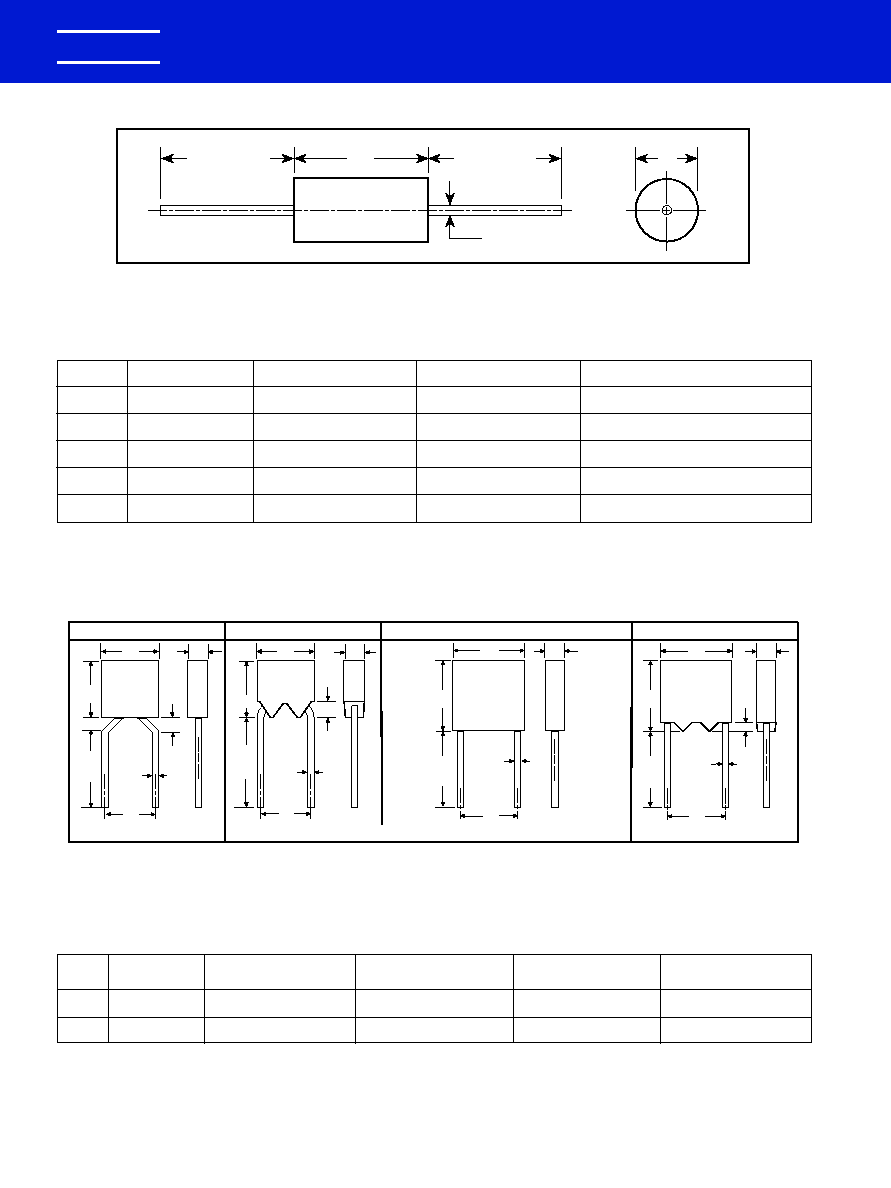
CERAMIC MOLDED/MIL-C-11015 (CK) & MIL-PRF-39014 (CKR)
KEMET Electronics Corporation, P.O. Box 5928, Greenville, S.C. 29606, (864) 963-6300
26
KEMET
�
C062 (CK06, CKR06)
Lead Dia.
.025
(+.004
-.002)
W
.026
MIN.
H
L
S
W
.045
MAX.
H
1.25
MIN.
L
S
W
H
1.25
MIN.
L
S
W
Center Line of leads within .030" of Center Line of case.
H
1.25
MIN.
S
.026
MIN.
L
C052 (CK05, CKR05)
C056 (CKR05)
C066 (CKR06)
Lead Dia.
.025
(+.004
-.002)
Lead Dia.
.025
(+.004
-.002)
Lead Dia.
.025
(+.004
-.002)
1.25
MIN.
*
*
*
*
DIMENSIONS -- INCHES & (MILLIMETERS)
CASE
MILITARY
SIZE
EQUIVALENT STYLES
L
D
C
C114
CK12, CKR11
.160 � .010 (4.06 � .25)
.090 � .010 (2.29 � .25)
.020, +.000, -.003 (.51, +.00, -.08)
C124
CK13, CKR12
.250 � .010 (6.35 � .25)
.090 � .010 (2.29 � .25)
.020, +.000, -.003 (.51, +.00, -.08)
C192
CK14, CKR14
.390 � .010 (9.91 � .25)
.140 � .010 (3.56 � .25)
.025, +.002, -.002 (.64, +.05, -.05)
C202
CK15, CKR15
.500 � .020 (12.70 � .51)
.250 � .015 (6.35 � .38)
.025, +.002, -.002 (.64, +.05, -.05)
C222
CK16, CKR16
.690 � .030 (17.53 � .76)
.350 � .020 (8.89 � .51)
.025, +.002, -.002 (.64, +.05, -.05)
D
L
C
1.50 Min.
(38.10)
1.50 Min.
(38.10)
CAPACITOR OUTLINE DRAWINGS (AXIAL LEADS)
CAPACITOR OUTLINE DRAWINGS (RADIAL LEADS)
DIMENSIONS -- INCHES & (MILLIMETERS)
MILITARY
S
CASE
EQUIVALENT
H
L
W
LEAD
SIZE
STYLES
HEIGHT
LENGTH
WIDTH
SPACING
CK05, CKR05
.190 � .010 (4.83 � .25)
.190 � .010 (4.83 � .25)
.090 � .010 (2.29 � .25)
.200 � .015 (5.08 � .38)
CK06, CKR06
.290 � .010 (7.37 � .25)
.290 � .010 (7.37 � .25)
.090 � .010 (2.29 � .25)
.200 � .015 (5.08 � .38)
C052/
C056
C062/
C066
*
Leads are .625 minimum when tape and reel packaged.
0988 Layout rev 8/9/2000 9:54 AM Page 26
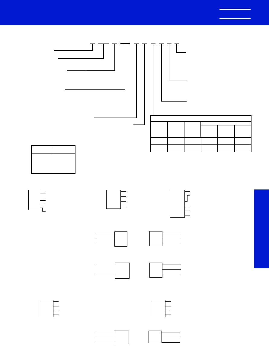
KEMET
�
CERAMIC MOLDED/MIL-C-11015 & MIL-PRF-39014
C114T (CKR11)
K
102
052
C
5
K
A
X
2
C
CERAMIC
*CASE SIZE
(See Table Below)
SPECIFICATION
Military
T -- MIL-PRF-39014
K -- MIL-C-11015
CAPACITANCE
In picofarad code: First two digits are significant
figures and third is number of zeroes following
(except 9 indicates division by 10). Examples:
0.1 F = 100,000 pF = 104 and 9.1 pF = 919.
See tables for Standard Values.
FAILURE RATE
INTERNAL CONSTRUCTION
CAPACITANCE TOLERANCE
Standard
M --
�
20%
K --
�
10%
A -- Not Applicable (Std.)
M -- 1.0%
P -- 0.1%
R -- 0.01%
S -- 0.001%
LEAD MATERIAL
C -- Standard
5 -- Standard
WORKING
VOLTAGE
1 -- 100
2 -- 200
5 --
50
Standard tolerances for each Series are
shown in the repetitive parts lists.
*CASE SIZES
RADIAL
AXIAL
C052
C114
C056
C124
C062
C192
C066
C202
C222
TEMPERATURE CHARACTERISTIC
Capacitance Change With Temp.
Measured
Measured
Without
With Bias
KEMET
Military
EIA
Temp.
DC Bias
(Rated
Designator Equivalent
Equivalent
Range,
�
C
Voltage
Voltage)
X
BX
X7R
-55 to
�
15%
+15%
(Stable)
+125
-25%
R
BR
X7R
-55 to
�
15%
+15%
(Stable)
+125
-40%
**
**Part Number Example: C052K102K2X5CA (14 digits � no spaces)
ORDERING INFORMATION
MARKING INFORMATION
C114T (CKR11) THROUGH C222T (CKR16) PER MIL-PRF-39014
JK
103
KP0
37A
J for JAN
K for KEMET
Capacitance
Capacitance Tolerance, FR Level
& Date Code (Yr.)
Date and Lot Code
C124T (CKR12)
CKR12
2657J
0037A
31433
Style
Dash No., J for JAN
Date & Lot Code
Source Code
(Federal Supply Code
for Manufacturers,
FSCM)
C192T (CKR14) C202T (CKR15) C222T (CKR16)
M39014
5-2125
KEMET
0037A
J50V
105K
Complete Part Number
Manufacturer's Name
Date & Lot Code
JAN & Voltage
Capacitance, pF Code, Capacitance
Tolerance
C052/56T (CKR05) PER MIL-PRF-39014/01
JK
0037
A
JAN-KEMET
Date Code
Lot Code
BACK
M390
14/01
1579*
Specification
Sheet No.
Four Digit Part No.
*Add "V" as the last
digit for stand-off leads.
FRONT
C062/66T (CKR06) PER MIL-PRF-39014/02
0037A
J200V
103K
Date & Lot Code
JAN & Voltage
Capacitance, pF Code, Capacitance Tolerance
BACK
M39014
2-1338
*KEMET
Complete MIL Part No.
Manufacturer's Name
FRONT
*Add "V" as the last digit
for stand-off leads.
C114K (CK12) THROUGH C222K (CK16) PER MIL-C-11015
KEMET Electronics Corporation, P.O. Box 5928, Greenville, S.C. 29606, (864) 963-6300
27
MIL-C-11015
MIL-PRF-39014
C114K (CK12) C124K (CK13)
KCK
12BX
102K
0037
KEMET, CK
Style (12 or 13), Temp. Char. (BX or BR)
Capacitance, pF Code, Capacitance Tolerance
Date Code
C192K (CK14) C202K (CK15) C222K (CK16)
K100V
CK14BX
123K
0037
KEMET, Voltage
Style (14, 15 or 16), Temp. Char. (BX or BR)
Capacitance, pF Code, Capacitance Tolerance
Date Code
C052K (CK05) PER MIL-C-11015/18 & C062K (CK06) PER MIL-C-11015/19
200V
K
0001
Voltage
KEMET
Date Code
BACK
CK05
BX
102K
Style
Temperature Characteristic
Capacitance, pF Code, Capacitance Tolerance
FRONT
0988 Layout rev 8/9/2000 9:54 AM Page 27
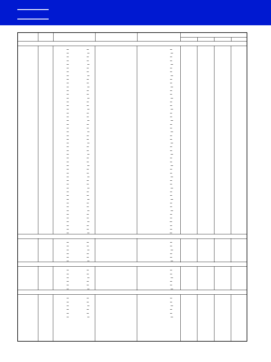
RATINGS & PART NUMBER REFERENCE
CERAMIC MOLDED/AXIAL -- MIL-C-11015 & MIL-PRF-39014
STABLE TEMPERATURE CHARACTERISTICS--BX & BR (EIA-X7R)
KEMET Electronics Corporation, P.O. Box 5928, Greenville, S.C. 29606, (864) 963-6300
28
KEMET
�
CAP.
TOL.
KEMET
MIL-PRF-39014/05 For Failure Rate Levels (2)
pF
%
PART NUMBER
MIL-C-11015/20
MIL-PRF-39014/05
M
P
R
S
100 VOLT -- C114 SIZE (MILITARY--CK12 or CKR11)
10
10
C114(1)100K1X5C(2)
CK12BX100K
CKR11BX100K(2)
2601
2801
2001
2201
10
20
C114(1)100M1X5C(2)
CK12BX100M
CKR11BX100M(2)
2602
2802
2002
2202
12
10
C114(1)120K1X5C(2)
CK12BX120K
CKR11BX120K(2)
2603
2803
2003
2203
15
10
C114(1)150K1X5C(2)
CK12BX150K
CKR11BX150K(2)
2604
2804
2004
2204
15
20
C114(1)150M1X5C(2)
CK12BX150M
CKR11BX150M(2)
2605
2805
2005
2205
18
10
C114(1)180K1X5C(2)
CK12BX180K
CKR11BX180K(2)
2606
2806
2006
2206
22
10
C114(1)220K1X5C(2)
CK12BX220K
CKR11BX220K(2)
2607
2807
2007
2207
22
20
C114(1)220M1X5C(2)
CK12BX220M
CKR11BX220M(2)
2608
2808
2008
2208
27
10
C114(1)270K1X5C(2)
CK12BX270K
CKR11BX270K(2)
2609
2809
2009
2209
33
10
C114(1)330K1X5C(2)
CK12BX330K
CKR11BX330K(2)
2610
2810
2010
2210
33
20
C114(1)330M1X5C(2)
CK12BX330M
CKR11BX330M(2)
2611
2811
2011
2211
39
10
C114(1)390K1X5C(2)
CK12BX390K
CKR11BX390K(2)
2612
2812
2012
2212
47
10
C114(1)470K1X5C(2)
CK12BX470K
CKR11BX470K(2)
2613
2813
2013
2213
47
20
C114(1)470M1X5C(2)
CK12BX470M
CKR11BX470M(2)
2614
2814
2014
2214
56
10
C114(1)560K1X5C(2)
CK12BX560K
CKR11BX560K(2)
2615
2815
2015
2215
68
10
C114(1)680K1X5C(2)
CK12BX680K
CKR11BX680K(2)
2616
2816
2016
2216
68
20
C114(1)680M1X5C(2)
CK12BX680M
CKR11BX680M(2)
2617
2817
2017
2217
82
10
C114(1)820K1X5C(2)
CK12BX820K
CKR11BX820K(2)
2618
2818
2018
2218
100
10
C114(1)101K1X5C(2)
CK12BX101K
CKR11BX101K(2)
2619
2819
2019
2219
100
20
C114(1)101M1X5C(2)
CK12BX101M
CKR11BX101M(2)
2620
2820
2020
2220
120
10
C114(1)121K1X5C(2)
CK12BX121K
CKR11BX121K(2)
2621
2821
2021
2221
150
10
C114(1)151K1X5C(2)
CK12BX151K
CKR11BX151K(2)
2622
2822
2022
2222
150
20
C114(1)151M1X5C(2)
CK12BX151M
CKR11BX151M(2)
2623
2823
2023
2223
180
10
C114(1)181K1X5C(2)
CK12BX181K
CKR11BX181K(2)
2624
2824
2024
2224
220
10
C114(1)221K1X5C(2)
CK12BX221K
CKR11BX221K(2)
2625
2825
2025
2225
220
20
C114(1)221M1X5C(2)
CK12BX221M
CKR11BX221M(2)
2626
2826
2026
2226
270
10
C114(1)271K1X5C(2)
CK12BX271K
CKR11BX271K(2)
2627
2827
2027
2227
330
10
C114(1)331K1X5C(2)
CK12BX331K
CKR11BX331K(2)
2628
2828
2028
2228
330
20
C114(1)331M1X5C(2)
CK12BX331M
CKR11BX331M(2)
2629
2829
2029
2229
390
10
C114(1)391K1X5C(2)
CK12BX391K
CKR11BX391K(2)
2630
2830
2030
2230
470
10
C114(1)471K1X5C(2)
CK12BX471K
CKR11BX471K(2)
2631
2831
2031
2231
470
20
C114(1)471M1X5C(2)
CK12BX471M
CKR11BX471M(2)
2632
2832
2032
2232
560
10
C114(1)561K1X5C(2)
CK12BX561K
CKR11BX561K(2)
2633
2833
2033
2233
680
10
C114(1)681K1X5C(2)
CK12BX681K
CKR11BX681K(2)
2634
2834
2034
2234
680
20
C114(1)681M1X5C(2)
CK12BX681M
CKR11BX681M(2)
2635
2835
2035
2235
820
10
C114(1)821K1X5C(2)
CK12BX821K
CKR11BX821K(2)
2636
2836
2036
2236
1,000
10
C114(1)102K1X5C(2)
CK12BX102K
CKR11BX102K(2)
2637
2837
2037
2237
1,000
20
C114(1)102M1X5C(2)
CK12BX102M
CKR11BX102M(2)
2638
2838
2038
2238
1,200
10
C114(1)122K1X5C(2)
CK12BX122K
CKR11BX122K(2)
2639
2839
2039
2239
1,500
10
C114(1)152K1X5C(2)
CK12BX152K
CKR11BX152K(2)
2640
2840
2040
2240
1,500
20
C114(1)152M1X5C(2)
CK12BX152M
CKR11BX152M(2)
2641
2841
2041
2241
1,800
10
C114(1)182K1X5C(2)
CK12BX182K
CKR11BX182K(2)
2642
2842
2042
2242
2,200
10
C114(1)222K1X5C(2)
CK12BX222K
CKR11BX222K(2)
2643
2843
2043
2243
2,200
20
C114(1)222M1X5C(2)
CK12BX222M
CKR11BX222M(2)
2644
2844
2044
2244
2,700
10
C114(1)272K1X5C(2)
CK12BX272K
CKR11BX272K(2)
2645
2845
2045
2245
3,300
10
C114(1)332K1X5C(2)
CK12BX332K
CKR11BX332K(2)
2646
2846
2046
2246
3,300
20
C114(1)332M1X5C(2)
CK12BX332M
CKR11BX332M2)
2647
2847
2047
2247
3,900
10
C114(1)392K1X5C(2)
CK12BX392K
CKR11BX392K(2)
2648
2848
2048
2248
4,700
10
C114(1)472K1X5C(2)
CK12BX472K
CKR11BX472K(2)
2649
2849
2049
2249
4,700
20
C114(1)472M1X5C(2)
CK12BX472M
CKR11BX472M2)
2650
2850
2050
2250
50 VOLT -- C114 SIZE (MILITARY--CK12 or CKR11)
5,600
10
C114(1)562K5X5C(2)
CK12BX562K
CKR11BX562K(2)
2651
2851
2051
2251
6,800
10
C114(1)682K5X5C(2)
CK12BX682K
CKR11BX682K(2)
2652
2852
2052
2252
6,800
20
C114(1)682M5X5C(2)
CK12BX682M
CKR11BX682M(2)
2653
2853
2053
2253
8,200
10
C114(1)822K5X5C(2)
CK12BX822K
CKR11BX822K(2)
2654
2854
2054
2254
10,000
10
C114(1)103K5X5C(2)
CK12BX103K
CKR11BX103K(2)
2655
2855
2055
2255
10,000
20
C114(1)103M5X5C(2)
CK12BX103M
CKR11BX103M(2)
2656
2856
2056
2256
100 VOLT -- C124 SIZE (MILITARY--CK13 or CKR12)
5,600
10
C124(1)562K1X5C(2)
CK13BX562K
CKR12BX562K(2)
2657
2857
2057
2257
6,800
10
C124(1)682K1X5C(2)
CK13BX682K
CKR12BX682K(2)
2658
2858
2058
2258
6,800
20
C124(1)682M1X5C(2)
CK13BX682M
CKR12BX682M(2)
2659
2859
2059
2259
8,200
10
C124(1)822K1X5C(2)
CK13BX822K
CKR12BX822K(2)
2660
2860
2060
2260
10,000
10
C124(1)103K1X5C(2)
CK13BX103K
CKR12BX103K(2)
2661
2861
2061
2261
10,000
20
C124(1)103M1X5C(2)
CK13BX103M
CKR12BX103M(2)
2662
2862
2062
2262
50 VOLT -- C124 SIZE (MILITARY--CK13 or CKR12)
12,000
10
C124(1)123K5X5C(2)
CK13BX123K
CKR12BX123K(2)
2663
2863
2063
2263
15,000
10
C124(1)153K5X5C(2)
CK13BX153K
CKR12BX153K(2)
2664
2864
2064
2264
15,000
20
C124(1)153M5X5C(2)
CK13BX153M
CKR12BX153M(2)
2665
2865
2065
2265
18,000
10
C124(1)183K5X5C(2)
CK13BX183K
CKR12BX183K(2)
2666
2866
2066
2266
22,000
10
C124(1)223K5X5C(2)
CK13BX223K
CKR12BX223K(2)
2667
2867
2067
2267
22,000
20
C124(1)223M5X5C(2)
CK13BX223M
CKR12BX223M(2)
2668
2868
2068
2268
27,000
10
C124K273K5R5CA
CK13BR273K
33,000
10
C124K333K5R5CA
CK13BR333K
33,000
20
C124K333M5R5CA
CK13BR333M
39,000
10
C124K393K5R5CA
CK13BR393K
47,000
10
C124K473K5R5CA
CK13BR473K
47,000
20
C124K473M5R5CA
CK13BR473M
(1) Insert proper letter for specification: K -- MIL-C-11015; T -- MIL-PRF-39014 (2) Failure Rate Designator: A -- Not applicable (MIL-C-11015); M -- 1%/1000 Hours,
P -- .1%/1000 Hours, R -- .01%/1000 Hours, S -- .001%/1000 Hours (MIL-PRF-39014)
0988 Layout rev 8/9/2000 9:54 AM Page 28

KEMET Electronics Corporation, P.O. Box 5928, Greenville, S.C. 29606, (864) 963-6300
29
KEMET
�
CERAMIC MOLDED/AXIAL -- MIL-C-11015 & MIL-PRF-39014
STABLE TEMPERATURE CHARACTERISTICS--BX & BR (EIA-X7R)
MIL-C-11015
MIL-PRF-39014
RATINGS & PART NUMBER REFERENCE
CAP.
TOL.
KEMET
MIL-PRF-39014/05 For Failure Rate Levels (2)
pF
%
PART NUMBER
MIL-C-11015/20
MIL-PRF-39014/05
M
P
R
S
50 VOLT -- C124 SIZE (MILITARY--CK13 or CKR12) (Cont'd)
27,000
10
C124T273K5X5C(2)
CKR12BX273K(2)
2669
2869
2069
2269
33,000
10
C124T333K5X5C(2)
CKR12BX333K(2)
2670
2870
2070
2270
33,000
20
C124T333M5X5C(2)
CKR12BX333M(2)
2671
2871
2071
2271
39,000
10
C124T393K5X5C(2)
CKR12BX393K(2)
2672
2872
2072
2272
47,000
10
C124T473K5X5C(2)
CKR12BX473K(2)
2673
2873
2073
2273
47,000
20
C124T473M5X5C(2)
CKR12BX473M(2)
2674
2874
2074
2274
100 VOLT -- C192 SIZE (MILITARY--CK14 or CKR14)
12,000
10
C192(1)123K1X5C(2)
CK14BX123K
CKR14BX123K(2)
2675
2875
2075
2275
15,000
10
C192(1)153K1X5C(2)
CK14BX153K
CKR14BX153K(2)
2676
2876
2076
2276
15,000
20
C192(1)153M1X5C(2)
CK14BX153M
CKR14BX153M(2)
2677
2877
2077
2277
18,000
10
C192(1)183K1X5C(2)
CK14BX183K
CKR14BX183K(2)
2678
2878
2078
2278
22,000
10
C192(1)223K1X5C(2)
CK14BX223K
CKR14BX223K(2)
2679
2879
2079
2279
22,000
20
C192(1)223M1X5C(2)
CK14BX223M
CKR14BX223M(2)
2680
2880
2080
2280
27,000
10
C192(1)273K1X5C(2)
CK14BX273K
CKR14BX273K(2)
2681
2881
2081
2281
33,000
10
C192(1)333K1X5C(2)
CK14BX333K
CKR14BX333K(2)
2682
2882
2082
2282
33,000
20
C192(1)333M1X5C(2)
CK14BX333M
CKR14BX333M(2)
2683
2883
2083
2283
39,000
10
C192(1)393K1X5C(2)
CK14BX393K
CKR14BX393K(2)
2684
2884
2084
2284
47,000
10
C192(1)473K1X5C(2)
CK14BX473K
CKR14BX473K(2)
2685
2885
2085
2285
47,000
20
C192(1)473M1X5C(2)
CK14BX473M
CKR14BX473M(2)
2686
2886
2086
2286
56,000
10
C192(1)563K1R5C(2)
CK14BR563K
CKR14BR563K(2)
2693
2893
2093
2293
68,000
10
C192(1)683K1R5C(2)
CK14BR683K
CKR14BR683K(2)
2694
2894
2094
2294
68,000
20
C192(1)683M1R5C(2)
CK14BR683M
CKR14BR683M(2)
2695
2895
2095
2295
82,000
10
C192(1)823K1R5C(2)
CK14BR823K
CKR14BR823K(2)
2696
2896
2096
2296
100,000
10
C192(1)104K1R5C(2)
CK14BR104K
CKR14BR104K(2)
2697
2897
2097
2297
100,000
20
C192(1)104M1R5C(2)
CK14BR104M
CKR14BR104M(2)
2698
2898
2098
2298
50 VOLT -- C192 SIZE (MILITARY--CK14 or CKR14)
56,000
10
C192T563K5X5C(2)
CKR14BX563K(2)
2687
2887
2087
2287
68,000
10
C192T683K5X5C(2)
CKR14BX683K(2)
2688
2888
2088
2288
68,000
20
C192T683M5X5C(2)
CKR14BX683M(2)
2689
2889
2089
2289
82,000
10
C192T823K5X5C(2)
CKR14BX823K(2)
2690
2890
2090
2290
100,000
10
C192T104K5X5C(2)
CKR14BX104K(2)
2691
2891
2091
2291
100,000
20
C192T104M5X5C(2)
CKR14BX104M(2)
2692
2892
2092
2292
120,000
10
C192(1)124K5R5C(2)
CK14BR124K
CKR14BR124K(2)
2699
2899
2099
2299
150,000
10
C192(1)154K5R5C(2)
CK14BR154K
CKR14BR154K(2)
2700
2900
2100
2300
150,000
20
C192(1)154M5R5C(2)
CK14BR154M
CKR14BR154M(2)
2701
2901
2101
2301
180,000
10
C192(1)184K5R5C(2)
CK14BR184K
CKR14BR184K(2)
2702
2902
2102
2302
220,000
10
C192(1)224K5R5C(2)
CK14BR224K
CKR14BR224K(2)
2703
2903
2103
2303
220,000
20
C192(1)224M5R5C(2)
CK14BR224M
CKR14BR224M(2)
2704
2904
2104
2304
270,000
10
C192(1)274K5R5C(2)
CK14BR274K
CKR14BR274K(2)
2705
2905
2105
2305
100 VOLT -- C202 SIZE (MILITARY--CK15 or CKR15)
56,000
10
C202T563K1X5C(2)
CKR15BX563K(2)
2706
2906
2106
2306
68,000
10
C202T683K1X5C(2)
CKR15BX683K(2)
2707
2907
2107
2307
68,000
20
C202T683M1X5C(2)
CKR15BX683M(2)
2708
2908
2108
2308
82,000
10
C202T823K1X5C(2)
CKR15BX823K(2)
2709
2909
2109
2309
100,000
10
C202(1)104K1X5C(2)
CK15BX104K
CKR15BX104K(2)
2710
2910
2110
2310
100,000
20
C202(1)104M1X5C(2)
CK15BX104M
CKR15BX104M(2)
2711
2911
2111
2311
120,000
10
C202(1)124K1R5C(2)
CK15BR124K
CKR15BR124K(2)
2712
2912
2112
2312
150,000
10
C202(1)154K1R5C(2)
CK15BR154K
CKR15BR154K(2)
2713
2913
2113
2313
150,000
20
C202(1)154M1R5C(2)
CK15BR154M
CKR15BR154M(2)
2714
2914
2114
2314
180,000
10
C202(1)184K1R5C(2)
CK15BR184K
CKR15BR184K(2)
2715
2915
2115
2315
220,000
10
C202(1)224K1R5C(2)
CK15BR224K
CKR15BR224K(2)
2716
2916
2116
2316
220,000
20
C202(1)224M1R5C(2)
CK15BR224M
CKR15BR224M(2)
2717
2917
2117
2317
270,000
10
C202(1)274K1R5C(2)
CK15BR274K
CKR15BR274K(2)
2718
2918
2118
2318
330,000
10
C202(1)334K1R5C(2)
CK15BR334K
CKR15BR334K(2)
2719
2919
2119
2319
330,000
20
C202(1)334M1R5C(2)
CK15BR334M
CKR15BR334M(2)
2720
2920
2120
2320
50 VOLT -- C202 SIZE (MILITARY--CK15 or CKR15)
470,000
10
C202(1)474K5R5C(2)
CK15BR474K
CKR15BR474K(2)
2721
2921
2121
2321
470,000
20
C202(1)474M5R5C(2)
CK15BR474M
CKR15BR474M(2)
2722
2922
2122
2322
680,000
10
C202T684K5R5C(2)
CKR15BR684K(2)
2723
2923
2123
2323
680,000
20
C202T684M5R5C(2)
CKR15BR684M(2)
2724
2924
2124
2324
1,000,000
10
C202(1)105K5R5C(2)
CK15BR105K
CKR15BR105K(2)
2725
2925
2125
2325
1,000,000
20
C202(1)105M5R5C(2)
CK15BR105M
CKR15BR105M(2)
2726
2926
2126
2326
100 VOLT -- C222 SIZE (MILITARY--CK16 or CKR16)
470,000
10
C222(1)474K1R5C(2)
CK16BR474K
CKR16BR474K(2)
2727
2927
2127
2327
470,000
20
C222(1)474M1R5C(2)
CK16BR474M
CKR16BR474M(2)
2728
2928
2128
2328
680,000
10
C222T684K1R5C(2)
CKR16BR684K(2)
2729
2929
2129
2329
680,000
20
C222T684M1R5C(2)
CKR16BR684M(2)
2730
2930
2130
2330
1,000,000
10
C222(1)105K1R5C(2)
CK16BR105K
CKR16BR105K(2)
2731
2931
2131
2331
1,000,000
20
C222(1)105M1R5C(2)
CK16BR105M
CKR16BR105M(2)
2732
2932
2132
2332
50 VOLT -- C222 SIZE (MILITARY--CK16 or CKR16)
2,200,000
10
C222(1)225K5R5C(2)
CK16BR225K
CKR16BR225K(2)
2733
2933
2133
2333
2,200,000
20
C222(1)225M5R5C(2)
CK16BR225M
CKR16BR225M(2)
2734
2934
2134
2334
3,300,000
10
C222(1)335K5R5C(2)
CK16BR335M
CKR16BR335K(2)
2735
2935
2135
2335
3,300,000
20
C222(1)335M5R5C(2)
CK16BR335M
CKR16BR335M(2)
2736
2936
2136
2336
(1) Insert proper letter for specification: K -- MIL-C-11015; T -- MIL-PRF-39014 (2) Failure Rate Designator: A -- Not applicable (MIL-C-11015); M -- 1%/1000 Hours,
P -- .1%/1000 Hours, R -- .01%/1000 Hours, S -- .001%/1000 Hours (MIL-PRF-39014)
0988 Layout rev 8/9/2000 9:54 AM Page 29
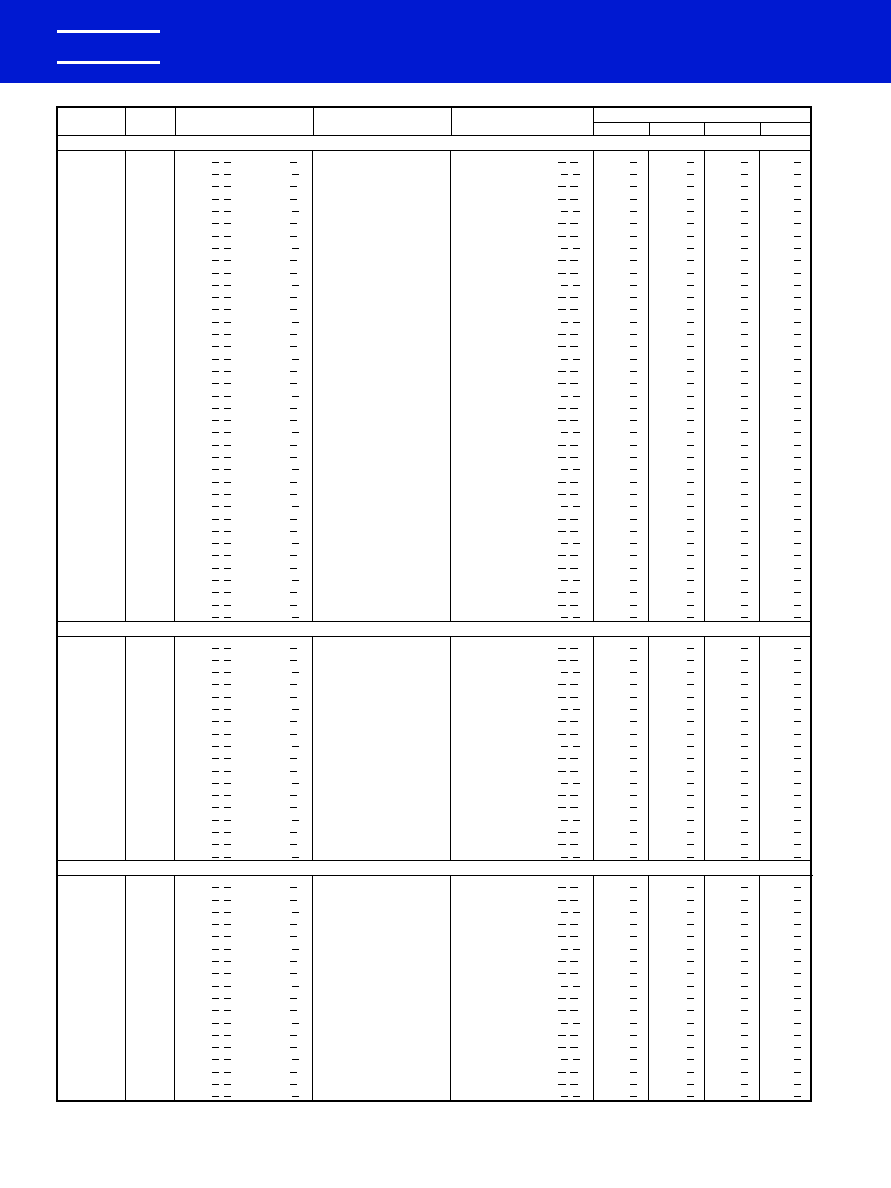
KEMET Electronics Corporation, P.O. Box 5928, Greenville, S.C. 29606, (864) 963-6300
CERAMIC MOLDED/RADIAL -- MIL-C-11015 & MIL-PRF-39014
STABLE TEMPERATURE CHARACTERISTICS--BX & BR (EIA-X7R)
30
KEMET
�
RATINGS & PART NUMBER REFERENCE
CAP.
TOL.
KEMET
MIL-PRF-39014/01 For Failure Rate Levels (2)
pF
%
PART NUMBER
MIL-C-11015/18
MIL-PRF-39014/01
M
P
R
S
200 VOLT -- C052/C056 SIZE (MILITARY--CK05 or CKR05)
10
10
C05(4)(1)100K2X5C(2)
CK05BX100K
CKR05BX100K(2)(3)
1201(3)
1241(3)
1281(3)
1321(3)
10
20
C05(4)(1)100M2X5C(2)
CK05BX100M
CKR05BX100M(2)(3)
1202(3)
1242(3)
1282(3)
1322(3)
12
10
C05(4)(1)120K2X5C(2)
CK05BX120K
CKR05BX120K(2)(3)
1203(3)
1243(3)
1283(3)
1323(3)
15
10
C05(4)(1)150K2X5C(2)
CK05BX150K
CKR05BX150K(2)(3)
1204(3)
1244(3)
1284(3)
1324(3)
15
20
C05(4)(1)150M2X5C(2)
CK05BX150M
CKR05BX150M(2)(3)
1205(3)
1245(3)
1285(3)
1325(3)
18
10
C05(4)(1)180K2X5C(2)
CK05BX180K
CKR05BX180K(2)(3)
1206(3)
1246(3)
1286(3)
1326(3)
22
10
C05(4)(1)220K2X5C(2)
CK05BX220K
CKR05BX220K(2)(3)
1207(3)
1247(3)
1287(3)
1327(3)
22
20
C05(4)(1)220M2X5C(2)
CK05BX220M
CKR05BX220M(2)(3)
1208(3)
1248(3)
1288(3)
1328(3)
27
10
C05(4)(1)270K2X5C(2)
CK05BX270K
CKR05BX270K(2)(3)
1209(3)
1249(3)
1289(3)
1329(3)
33
10
C05(4)(1)330K2X5C(2)
CK05BX330K
CKR05BX330K(2)(3)
1210(3)
1250(3)
1290(3)
1330(3)
33
20
C05(4)(1)330M2X5C(2)
CK05BX330M
CKR05BX330M(2)(3)
1211(3)
1251(3)
1291(3)
1331(3)
39
10
C05(4)(1)390K2X5C(2)
CK05BX390K
CKR05BX390K(2)(3)
1212(3)
1252(3)
1292(3)
1332(3)
47
10
C05(4)(1)470K2X5C(2)
CK05BX470K
CKR05BX470K(2)(3)
1213(3)
1253(3)
1293(3)
1333(3)
47
20
C05(4)(1)470M2X5C(2)
CK05BX470M
CKR05BX470M(2)(3)
1214(3)
1254(3)
1294(3)
1334(3)
56
10
C05(4)(1)560K2X5C(2)
CK05BX560K
CKR05BX560K(2)(3)
1215(3)
1255(3)
1295(3)
1335(3)
68
10
C05(4)(1)680K2X5C(2)
CK05BX680K
CKR05BX680K(2)(3)
1216(3)
1256(3)
1296(3)
1336(3)
68
20
C05(4)(1)680M2X5C(2)
CK05BX680M
CKR05BX680M(2)(3)
1217(3)
1257(3)
1297(3)
1337(3)
82
10
C05(4)(1)820K2X5C(2)
CK05BX820K
CKR05BX820K(2)(3)
1218(3)
1258(3)
1298(3)
1338(3)
100
10
C05(4)(1)101K2X5C(2)
CK05BX101K
CKR05BX101K(2)(3)
1219(3)
1259(3)
1299(3)
1339(3)
100
20
C05(4)(1)101M2X5C(2)
CK05BX101M
CKR05BX101M(2)(3)
1220(3)
1260(3)
1300(3)
1340(3)
120
10
C05(4)(1)121K2X5C(2)
CK05BX121K
CKR05BX121K(2)(3)
1221(3)
1261(3)
1301(3)
1341(3)
150
10
C05(4)(1)151K2X5C(2)
CK05BX151K
CKR05BX151K(2)(3)
1222(3)
1262(3)
1302(3)
1342(3)
150
20
C05(4)(1)151M2X5C(2)
CK05BX151M
CKR05BX151M(2)(3)
1223(3)
1263(3)
1303(3)
1343(3)
180
10
C05(4)(1)181K2X5C(2)
CK05BX181K
CKR05BX181K(2)(3)
1224(3)
1264(3)
1304(3)
1344(3)
220
10
C05(4)(1)221K2X5C(2)
CK05BX221K
CKR05BX221K(2)(3)
1225(3)
1265(3)
1305(3)
1345(3)
220
20
C05(4)(1)221M2X5C(2)
CK05BX221M
CKR05BX221M(2)(3)
1226(3)
1266(3)
1306(3)
1346(3)
270
10
C05(4)(1)271K2X5C(2)
CK05BX271K
CKR05BX271K(2)(3)
1227(3)
1267(3)
1307(3)
1347(3)
330
10
C05(4)(1)331K2X5C(2)
CK05BX331K
CKR05BX331K(2)(3)
1228(3)
1268(3)
1308(3)
1348(3)
330
20
C05(4)(1)331M2X5C(2)
CK05BX331M
CKR05BX331M(2)(3)
1229(3)
1269(3)
1309(3)
1349(3)
390
10
C05(4)(1)391K2X5C(2)
CK05BX391K
CKR05BX391K(2)(3)
1230(3)
1270(3)
1310(3)
1350(3)
470
10
C05(4)(1)471K2X5C(2)
CK05BX471K
CKR05BX471K(2)(3)
1231(3)
1271(3)
1311(3)
1351(3)
470
20
C05(4)(1)471M2X5C(2)
CK05BX471M
CKR05BX471M(2)(3)
1232(3)
1272(3)
1312(3)
1352(3)
560
10
C05(4)(1)561K2X5C(2)
CK05BX561K
CKR05BX561K(2)(3)
1233(3)
1273(3)
1313(3)
1353(3)
680
10
C05(4)(1)681K2X5C(2)
CK05BX681K
CKR05BX681K(2)(3)
1234(3)
1274(3)
1314(3)
1354(3)
680
20
C05(4)(1)681M2X5C(2)
CK05BX681M
CKR05BX681M(2)(3)
1235(3)
1275(3)
1315(3)
1355(3)
820
10
C05(4)(1)821K2X5C(2)
CK05BX821K
CKR05BX821K(2)(3)
1236(3)
1276(3)
1316(3)
1356(3)
1,000
10
C05(4)(1)102K2X5C(2)
CK05BX102K
CKR05BX102K(2)(3)
1237(3)
1277(3)
1317(3)
1357(3)
1,000
20
C05(4)(1)102M2X5C(2)
CK05BX102M
CKR05BX102M(2)(3)
1238(3)
1278(3)
1318(3)
1358(3)
100 VOLT -- C052/C056 SIZE (MILITARY--CK05 or CKR05)
1,200
10
C05(4)(1)122K1X5C(2)
CK05BX122K
CKR05BX122K(2)(3)
1239(3)
1279(3)
1319(3)
1359(3)
1,500
10
C05(4)(1)152K1X5C(2)
CK05BX152K
CKR05BX152K(2)(3)
1240(3)
1280(3)
1320(3)
1360(3)
1,500
20
C05(4)(1)152M1X5C(2)
CK05BX152M
CKR05BX152M(2)(3)
1441(3)
1481(3)
1521(3)
1561(3)
1,800
10
C05(4)(1)182K1X5C(2)
CK05BX182K
CKR05BX182K(2)(3)
1442(3)
1482(3)
1522(3)
1562(3)
2,200
10
C05(4)(1)222K1X5C(2)
CK05BX222K
CKR05BX222K(2)(3)
1443(3)
1483(3)
1523(3)
1563(3)
2,200
20
C05(4)(1)222M1X5C(2)
CK05BX222M
CKR05BX222M(2)(3)
1444(3)
1484(3)
1524(3)
1564(3)
2,700
10
C05(4)(1)272K1X5C(2)
CK05BX272K
CKR05BX272K(2)(3)
1445(3)
1485(3)
1525(3)
1565(3)
3,300
10
C05(4)(1)332K1X5C(2)
CK05BX332K
CKR05BX332K(2)(3)
1446(3)
1486(3)
1526(3)
1566(3)
3,300
20
C05(4)(1)332M1X5C(2)
CK05BX332M
CKR05BX332M(2)(3)
1447(3)
1487(3)
1527(3)
1567(3)
3,900
10
C05(4)(1)392K1X5C(2)
CK05BX392K
CKR05BX392K(2)(3)
1448(3)
1488(3)
1528(3)
1568(3)
4,700
10
C05(4)(1)472K1X5C(2)
CK05BX472K
CKR05BX472K(2)(3)
1449(3)
1489(3)
1529(3)
1569(3)
4,700
20
C05(4)(1)472M1X5C(2)
CK05BX472M
CKR05BX472M(2)(3)
1450(3)
1490(3)
1530(3)
1570(3)
5,600
10
C05(4)(1)562K1X5C(2)
CK05BX562K
CKR05BX562K(2)(3)
1451(3)
1491(3)
1531(3)
1571(3)
6,800
10
C05(4)(1)682K1X5C(2)
CK05BX682K
CKR05BX682K(2)(3)
1452(3)
1492(3)
1532(3)
1572(3)
6,800
20
C05(4)(1)682M1X5C(2)
CK05BX682M
CKR05BX682M(2)(3)
1453(3)
1493(3)
1533(3)
1573(3)
8,200
10
C05(4)(1)822K1X5C(2)
CK05BX822K
CKR05BX822K(2)(3)
1454(3)
1494(3)
1534(3)
1574(3)
10,000
10
C05(4)(1)103K1X5C(2)
CK05BX103K
CKR05BX103K(2)(3)
1455(3)
1495(3)
1535(3)
1575(3)
10,000
20
C05(4)(1)103M1X5C(2)
CK05BX103M
CKR05BX103M(2)(3)
1456(3)
1496(3)
1536(3)
1576(3)
50 VOLT -- C052/C056 SIZE (MILITARY--CK05 or CKR05)
12,000
10
C05(4)(1)123K5X5C(2)
CK05BX123K
CKR05BX123K(2)(3)
1457(3)
1497(3)
1537(3)
1577(3)
15,000
10
C05(4)(1)153K5X5C(2)
CK05BX153K
CKR05BX153K(2)(3)
1458(3)
1498(3)
1538(3)
1578(3)
15,000
20
C05(4)(1)153M5X5C(2)
CK05BX153M
CKR05BX153M(2)(3)
1459(3)
1499(3)
1539(3)
1579(3)
18,000
10
C05(4)(1)183K5X5C(2)
CK05BX183K
CKR05BX183K(2)(3)
1460(3)
1500(3)
1540(3)
1580(3)
22,000
10
C05(4)(1)223K5X5C(2)
CK05BX223K
CKR05BX223K(2)(3)
1461(3)
1501(3)
1541(3)
1581(3)
22,000
20
C05(4)(1)223M5X5C(2)
CK05BX223M
CKR05BX223M(2)(3)
1462(3)
1502(3)
1542(3)
1582(3)
27,000
10
C05(4)(1)273K5X5C(2)
CK05BX273K
CKR05BX273K(2)(3)
1463(3)
1503(3)
1543(3)
1583(3)
33,000
10
C05(4)(1)333K5X5C(2)
CK05BX333K
CKR05BX333K(2)(3)
1464(3)
1504(3)
1544(3)
1584(3)
33,000
20
C05(4)(1)333M5X5C(2)
CK05BX333M
CKR05BX333M(2)(3)
1465(3)
1505(3)
1545(3)
1585(3)
39,000
10
C05(4)(1)393K5X5C(2)
CK05BX393K
CKR05BX393K(2)(3)
1466(3)
1506(3)
1546(3)
1586(3)
47,000
10
C05(4)(1)473K5X5C(2)
CK05BX473K
CKR05BX473K(2)(3)
1467(3)
1507(3)
1547(3)
1587(3)
47,000
20
C05(4)(1)473M5X5C(2)
CK05BX473M
CKR05BX473M(2)(3)
1468(3)
1508(3)
1548(3)
1588(3)
56,000
10
C05(4)(1)563K5X5C(2)
CK05BX563K
CKR05BX563K(2)(3)
1469(3)
1509(3)
1549(3)
1589(3)
68,000
10
C05(4)(1)683K5X5C(2)
CK05BX683K
CKR05BX683K(2)(3)
1470(3)
1510(3)
1550(3)
1590(3)
68,000
20
C05(4)(1)683M5X5C(2)
CK05BX683M
CKR05BX683M(2)(3)
1471(3)
1511(3)
1551(3)
1591(3)
82,000
10
C05(4)(1)823K5X5C(2)
CK05BX823K
CKR05BX823K(2)(3)
1472(3)
1512(3)
1552(3)
1592(3)
100,000
10
C05(4)(1)104K5X5C(2)
CK05BX104K
CKR05BX104K(2)(3)
1473(3)
1513(3)
1553(3)
1593(3)
100,000
20
C05(4)(1)104M5X5C(2)
CK05BX104M
CKR05BX104M(2)(3)
1474(3)
1514(3)
1554(3)
1594(3)
(1) Insert proper letter for specification: K -- MIL-C-11015; T -- MIL-PRF-39014 (2) Failure Rate Designator: A -- Not applicable (MIL-C-11015); M -- 1%/1000 Hours,
P -- .1%/1000 Hours, R -- .01%/1000 Hours, S -- .001%/1000 Hours (MIL-PRF-39014)
(3) Insert "V" for standard design (C056). Leave blank for the flat bottom design (C052).
(4) Insert "2" for standard design (Style C052)
Note: Stand-offs are available only
Insert "6" for stand-off design (Style C056)
with the CKR, not the CK.
}
0988 Layout rev 8/9/2000 9:54 AM Page 30
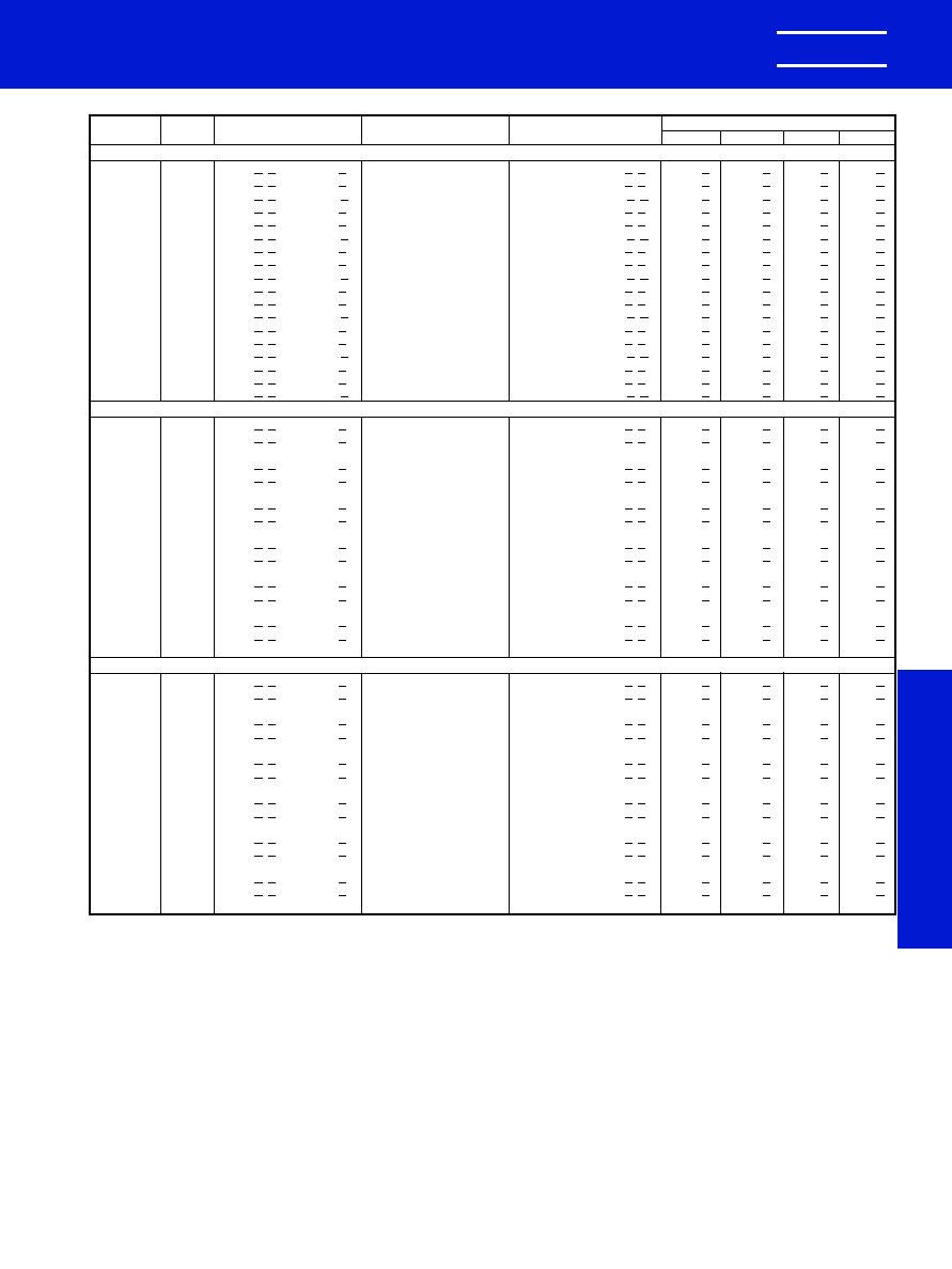
KEMET Electronics Corporation, P.O. Box 5928, Greenville, S.C. 29606, (864) 963-6300
31
KEMET
�
CERAMIC MOLDED/RADIAL -- MIL-C-11015 & MIL-PRF-39014
STABLE TEMPERATURE CHARACTERISTICS--BX & BR (EIA-X7R)
MIL-C-11015
MIL-PRF-39014
RATINGS & PART NUMBER REFERENCE
CAP.
TOL.
KEMET
MIL-PRF-39014/02 For Failure Rate Levels (2)
pF
%
PART NUMBER
MIL-C-11015/19
MIL-PRF-39014/02
M
P
R
S
200 VOLT -- C062/C066 SIZE (MILITARY--CK06 or CKR06)
1,200
10
C06(4)(1)122K2X5C(2)
CK06BX122K
CKR06BX122K(2)(3)
1201(3)
1241(3)
1281(3)
1321(3)
1,500
10
C06(4)(1)152K2X5C(2)
CK06BX152K
CKR06BX152K(2)(3)
1202(3)
1242(3)
1282(3)
1322(3)
1,500
20
C06(4)(1)152M2X5C(2)
CK06BX152M
CKR06BX152M(2)(3)
1203(3)
1243(3)
1283(3)
1323(3)
1,800
10
C06(4)(1)182K2X5C(2)
CK06BX182K
CKR06BX182K(2)(3)
1204(3)
1244(3)
1284(3)
1324(3)
2,200
10
C06(4)(1)222K2X5C(2)
CK06BX222K
CKR06BX222K(2)(3)
1206(3)
1246(3)
1286(3)
1326(3)
2,200
20
C06(4)(1)222M2X5C(2)
CK06BX222M
CKR06BX222M(2)(3)
1207(3)
1247(3)
1287(3)
1327(3)
2,700
10
C06(4)(1)272K2X5C(2)
CK06BX272K
CKR06BX272K(2)(3)
1208(3)
1248(3)
1288(3)
1328(3)
3,300
10
C06(4)(1)332K2X5C(2)
CK06BX332K
CKR06BX332K(2)(3)
1209(3)
1249(3)
1289(3)
1329(3)
3,300
20
C06(4)(1)332M2X5C(2)
CK06BX332M
CKR06BX332M(2)(3)
1210(3)
1250(3)
1290(3)
1330(3)
3,900
10
C06(4)(1)392K2X5C(2)
CK06BX392K
CKR06BX392K(2)(3)
1211(3)
1251(3)
1291(3)
1331(3)
4,700
10
C06(4)(1)472K2X5C(2)
CK06BX472K
CKR06BX472K(2)(3)
1212(3)
1252(3)
1292(3)
1332(3)
4,700
20
C06(4)(1)472M2X5C(2)
CK06BX472M
CKR06BX472M(2)(3)
1213(3)
1253(3)
1293(3)
1333(3)
5,600
10
C06(4)(1)562K2X5C(2)
CK06BX562K
CKR06BX562K(2)(3)
1214(3)
1254(3)
1294(3)
1334(3)
6,800
10
C06(4)(1)682K2X5C(2)
CK06BX682K
CKR06BX682K(2)(3)
1215(3)
1255(3)
1295(3)
1335(3)
6,800
20
C06(4)(1)682M2X5C(2)
CK06BX682M
CKR06BX682M(2)(3)
1216(3)
1256(3)
1296(3)
1336(3)
8,200
10
C06(4)(1)822K2X5C(2)
CK06BX822K
CKR06BX822K(2)(3)
1217(3)
1257(3)
1297(3)
1337(3)
10,000
10
C06(4)(1)103K2X5C(2)
CK06BX103K
CKR06BX103K(2)(3)
1218(3)
1258(3)
1298(3)
1338(3)
10,000
20
C06(4)(1)103M2X5C(2)
CK06BX103M
CKR06BX103M(2)(3)
1219(3)
1259(3)
1299(3)
1339(3)
100 VOLT -- C062/C066 SIZE (MILITARY--CK06 or CKR06)
12,000
10
C06(4)(1)123K1X5C(2)
CK06BX123K
CKR06BX123K(2)(3)
1231(3)
1271(3)
1311(3)
1351(3)
15,000
10
C06(4)(1)153K1X5C(2)
CK06BX153K
CKR06BX153K(2)(3)
1220(3)
1260(3)
1300(3)
1340(3)
15,000
20
C062K153M1X5CA
CK06BX153M
18,000
10
C06(4)(1)183K1X5C(2)
CK06BX183K
CKR06BX183K(2)(3)
1221(3)
1261(3)
1301(3)
1341(3)
22,000
10
C06(4)(1)223K1X5C(2)
CK06BX223K
CKR06BX223K(2)(3)
1222(3)
1262(3)
1302(3)
1342(3)
22,000
20
C062K223M1X5CA
CK06BX223M
27,000
10
C06(4)(1)273K1X5C(2)
CK06BX273K
CKR06BX273K(2)(3)
1232(3)
1272(3)
1312(3)
1352(3)
33,000
10
C06(4)(1)333K1X5C(2)
CK06BX333K
CKR06BX333K(2)(3)
1223(3)
1263(3)
1303(3)
1343(3)
33,000
20
C062K333M1X5CA
CK06BX333M
39,000
10
C06(4)(1)393K1X5C(2)
CK06BX393K
CKR06BX393K(2)(3)
1224(3)
1264(3)
1304(3)
1344(3)
47,000
10
C06(4)(1)473K1X5C(2)
CK06BX473K
CKR06BX473K(2)(3)
1225(3)
1265(3)
1305(3)
1345(3)
47,000
20
C062K473M1X5CA
CK06BX473M
56,000
10
C06(4)(1)563K1X5C(2)
CK06BX563K
CKR06BX563K(2)(3)
1226(3)
1266(3)
1306(3)
1346(3)
68,000
10
C06(4)(1)683K1X5C(2)
CK06BX683K
CKR06BX683K(2)(3)
1227(3)
1267(3)
1307(3)
1347(3)
68,000
20
C062K683M1X5CA
CK06BX683M
82,000
10
C06(4)(1)823K1X5C(2)
CK06BX823K
CKR06BX823K(2)(3)
1229(3)
1269(3)
1309(3)
1349(3)
100,000
10
C06(4)(1)104K1X5C(2)
CK06BX104K
CKR06BX104K(2)(3)
1230(3)
1270(3)
1310(3)
1350(3)
100,000
20
C062K104M1X5CA
CK06BX104M
50 VOLT -- C062/C066 SIZE (MILITARY--CK06 or CKR06)
120,000
10
C06(4)(1)124K5X5C(2)
CK06BX124K
CKR06BX124K(2)(3)
1233(3)
1273(3)
1313(3)
1353(3)
150,000
10
C06(4)(1)154K5X5C(2)
CK06BX154K
CKR06BX154K(2)(3)
1234(3)
1274(3)
1314(3)
1354(3)
150,000
20
C062K154M5X5CA
CK06BX154M
180,000
10
C06(4)(1)184K5X5C(2)
CK06BX184K
CKR06BX184K(2)(3)
1235(3)
1275(3)
1315(3)
1355(3)
220,000
10
C06(4)(1)224K5X5C(2)
CK06BX224K
CKR06BX224K(2)(3)
1236(3)
1276(3)
1316(3)
1356(3)
220,000
20
C062K224M5X5CA
CK06BX224M
270,000
10
C06(4)(1)274K5X5C(2)
CK06BX274K
CKR06BX274K(2)(3)
1237(3)
1277(3)
1317(3)
1357(3)
330,000
10
C06(4)(1)334K5X5C(2)
CK06BX334K
CKR06BX334K(2)(3)
1238(3)
1278(3)
1318(3)
1358(3)
330,000
20
C062K334M5X5CA
CK06BX334M
390,000
10
C06(4)(1)394K5X5C(2)
CK06BX394K
CKR06BX394K(2)(3)
1239(3)
1279(3)
1319(3)
1359(3)
470,000
10
C06(4)(1)474K5X5C(2)
CK06BX474K
CKR06BX474K(2)(3)
1240(3)
1280(3)
1320(3)
1360(3)
470,000
20
C062K474M5X5CA
CK06BX474M
560,000
10
C06(4)(1)564K5X5C(2)
CK06BX564K
CKR06BX564K(2)(3)
1404(3)
1408(3)
1412(3)
1416(3)
680,000
10
C06(4)(1)684K5X5C(2)
CK06BX684K
CKR06BX684K(2)(3)
1405(3)
1409(3)
1413(3)
1417(3)
680,000
20
C062K684M5X5CA
CK06BX684M
820,000
10
C06(4)(1)824K5X5C(2)
CK06BX824K
CKR06BX824K(2)(3)
1406(3)
1410(3)
1414(3)
1418(3)
1,000,000
10
C06(4)(1)105K5X5C(2)
CK06BX105K
CKR06BX105K(2)(3)
1407(3)
1411(3)
1415(3)
1419(3)
1,000,000
20
C062K105M5X5CA
CK06BX105M
(1) Insert proper letter for specification: K -- MIL-C-11015; T -- MIL-PRF-39014.
(2) Failure Rate Designator: A -- Not applicable (MIL-C-11015); M -- 1%/1000 Hours, P -- .1%/1000 Hours, R -- .01%/1000 Hours, S -- .001%/1000 Hours (MIL-PRF-39014)
(3) Add "V" for stand-off design (C066). Leave blank for the flat bottom design (C062).
(4) Insert "2" for standard design (Style C062). Insert "6" for stand-off design (Style C066). Note: Stand-offs are available only with the CKR, not the CK.
0988 Layout rev 8/9/2000 9:54 AM Page 31
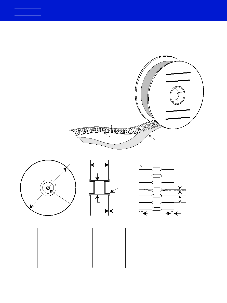
CERAMIC LEADED
PACKAGING INFORMATION
KEMET Electronics Corporation, P.O. Box 5928, Greenville, S.C. 29606, (864) 963-6300
32
KEMET
�
KEMET
�
KEMET
�
Adhesive Tape
Adhesive Tape
Kraft Paper
Interleaving
Figure 1
Figure 2
3
1
/
4
"
(82.6)
.655"
�
0.010"
(16.6
�
0.25)
10.5" - 14"
(26.67 -
35.56cm)
.059" to .315"
Greater Than
Component
Length
*
Hub
1/8"
(3.18)
Figure 3
See Table 1
(B)
.250" Nom.
(6.35)
*
.047" Max
(1.20)
See Table 1 (A)
Ceramic Axial
Lead Tape and Reel Packaging
KEMET offers standard reeling of Molded and Conformally
Coated Axial Leaded Ceramic Capacitors for automatic insertion
or lead forming machines per EIA specification RS-296.
Paper (50 lb.) test minimum is inserted between the layers of
capacitors wound on reels for component pitch
0.400".
Capacitor lead length may extend only a maximum of .0625"
(1.59mm) beyond the tapes' edges. Capacitors are centered in a
row between the two tapes and will deviate only
�
0.031
(0.79mm) from the row center. A minimum of 36" (91.5 cm) leader
tape is provided at each end of the reel capacitors. Universal
splicing clips are used to connect the tape. Standard reel
quantities are shown on page 34.
Dimensions in Inches & (Millimeters)
* Not Available for Conformally Coated Parts.
Component
Body Diameter
Component
Pitch "A"
Inside Tape Spacing "B"
�
1.5mm (0.059")
0.020" or (
�
0.5mm)
I
III*
0" (0mm) to 0.197" (5mm)
0.197" (5.01mm) to 0.394: (10mm)
0.197" or (5mm)
0.394" or (10mm)
2.062" (52.4mm)
2.874" (73mm)
Table 1
0988 Layout rev 8/9/2000 9:54 AM Page 32
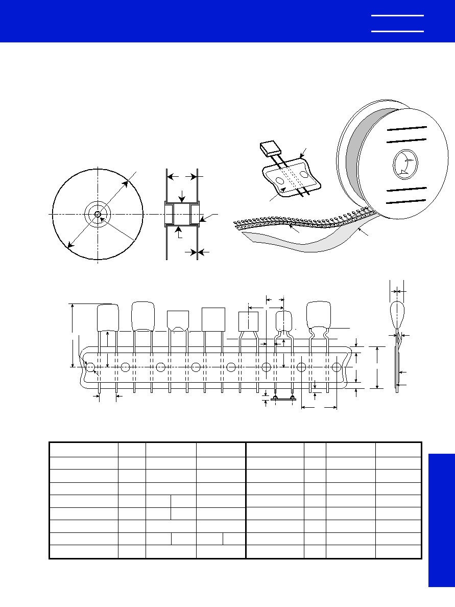
KEMET Electronics Corporation, P.O. Box 5928, Greenville, S.C. 29606, (864) 963-6300
33
KEMET
�
CERAMIC LEADED
PACKAGING INFORMATION
T
ape and Reel Packaging
Ceramic Radial Tape and Reel Dimensions in Millimeters & (Inches)
Figure 3: Standard Reel
Figure 1
3
1
/
4
"
(82.6)
.655"
�
0.010"
(16.6
�
0.25)
12"
(30.48 cm)
.059" to .315"
Greater Than
Over All
Height
of Taped
Components
*
Hub
1/8"
(3.18)
Ceramic Radial
Lead Tape and Reel Packaging
KEMET offers standard reeling of Molded and Conformally
Coated Radial Leaded Ceramic Capacitors for automatic
insertion per EIA specification RS-468. Parts are taped to a
tagboard carrier strip, and wound on a reel as shown in
Figure 1. Kraft paper interleaving is inserted between the
layers of capacitors on the reel. Ammopack is also available,
with the same lead tape configuration and package quantities.
KEMET
�
KEMET
�
Kraft Paper
Interleaving
Carrier Tape
Carrier Strip
Adhesive Tape
* Lead spacings are 2.54mm
(.10") center-to-center.
** Lead spacings are 5.08mm
(.20") center-to-center.
C317**
C322**
C323**
C333**
P
2
H
W
0
W
2
W
2
P
0
T
H
1
L
1
D
0
C315*
C320*
CK05**
CKR05**
C052**
C056**
C066**
CK06**
CKR06**
C062**
C330**
C340**
P
1MM Max.
(.039")
Tape
Carrier
H
P1
F
Figure 2: Lead Tape Configuration (See Table Below)
W
H
0
Sprocket Hole Diameter
Sprocket Hole Pitch
Component Pitch
Lead Spacing (1)
Sprocket Hole Center
to Lead Center (1)
Sprocket Hole Center
to Component Center
Height to Seating Plane
(straight leads) (2)
Component Height
Above Tape Center
Dimension
Symbol
Nominal
mm (inch)
Tolerance
mm (inch)
Dimension
Symbol
Nominal
mm (inch)
Tolerance
mm (inch)
Height to Seating
Plane (formed leads) (2)
Component Alignment
Lead Protrusion
Composite Tape
Thickness
Overall Tape and
Lead Thickness
Carrier Tape Width
Hold-Down Tape
Width
Hold-Down Tape
Location
Do
P0
P
F
P1
P2
H
H1
�
0.2 (.008)
�
0.3 (.012)
�
0.3 (.012)
+0.6 -0.2
(+.024 -.008)
�
0.7 (.028)
�
1.3 (.051)
C7301 C7303
�
0.5 (.020) Minimum
Maximum
C7301 C7303
16.0 (.630) 18.0 (.709)
4.0 (.157)
1.0 (.039)
0.7 (.051)
1.5 (.059)
18.0 (.709)
5.0 (.197)
3.0 (.118)
H
0
h
L1
t
T
W
W0
W2
C7301 C7303
�
0.5 (.020) Minimum
�
0.2 (.008)
Maximum
�
0.2 (.008)
Maximum
+1.0 - 0.5
(+.039 -.020)
Minimum
Maximum
(1) Measured at the egress from the carrier tape, on the component side.
(2) Determined by a 4 digit suffix placed at the end of the part number, as follows:
7301 =
7303 =
4.0 (.157)
12.7 (.500)
12.7 (.500)
5.08 2.54
(.20) (.10)
3.81 5.08
(.150) (.200)
6.35 (.250)
C7301 C7303
16.0 (.630) 18.0 (.709)
32.2 (1.27)
Recommended for parts with formed leads.
Recommended for parts with straight leads.
Example: C322C104K5R5CA7301
Example: C320C104K5R5CA7303
0988 Layout rev 8/9/2000 9:54 AM Page 33
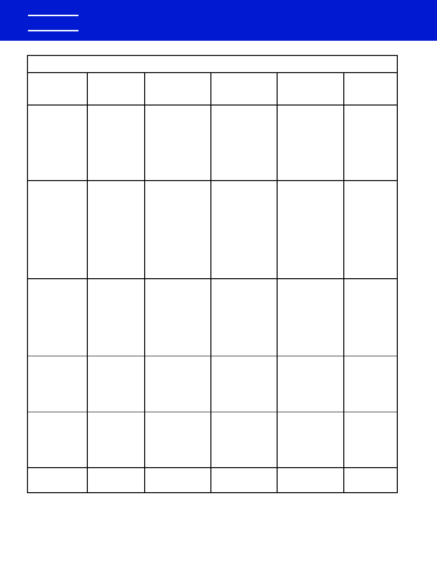
CERAMIC PACKAGING
Standard (1)
Standard
KEMET
Military
Military
Bulk
Reel
Reel
Number
Style
Specification
Quantity
Quantity
Size
C114C-K-G
CK12, CC75
MIL-C-11015/
200/Box
5000
12"
C124C-K-G
CK13, CC76
MIL-PRF-20
200/Box
5000
12"
C192C-K-G
CK14, CC77
100/Box
3000
12"
C202C-K
CK15
25/Box
500
12"
C222C-K
CK16
10/Tray
300
12"
C052C-K-G
CK05, CC05
100/Bag
2000
12"
C062C-K-G
CK06, CC06
100/Bag
1500
12"
C114G
CCR75
MIL-PRF-20
200/Box
5000
12"
C124G
CCR76
200/Box
5000
12"
C192G
CCR77
100/Box
3000
12"
C202G
CC78-CCR78
25/Box
500
12"
C222G
CC79-CCR79
10/Tray
300
12"
C052/56G
CCR05
100/Bag
1700
12"
C062/66G
CCR06
100/Bag
1500
12"
C512G
CC07-CCR07
Footnote (2)
N/A
N/A
C522G
CC08-CCR08
Footnote (2)
N/A
N/A
C114T
CKR11
MIL-PRF-39014
200/Box
5000
12"
C124T
CKR12
200/Box
5000
12"
C192T
CKR14
100/Box
3000
12"
C202T
CKR15
25/Box
500
12"
C222T
CKR16
10/Tray
300
12"
C052/56T
CKR05
100/Bag
1700
12"
C062/66T
CKR06
100/Bag
1500
12"
C31X
500/Bag
2500
12"
C32X
500/Bag
2500
12"
C33X
250/Bag
1500
12"
C340
100/Bag
1000
12"
C350
50/Bag
N/A
N/A
C410
300/Box
5000
12"
C412
200/Box
5000
12"
C420
300/Box
5000
12"
C430
200/Box
2500
12"
C440
200/Box
2500
12"
C512
N/A
N/A
Footnote (2)
N/A
N/A
C522
N/A
N/A
Footnote (2)
N/A
N/A
CERAMIC LEADED
PACKAGING INFORMATION
KEMET Electronics Corporation, P.O. Box 5928, Greenville, S.C. 29606, (864) 963-6300
34
KEMET
�
NOTE: (1) Standard packaging refers to number of pieces per bag, box, tray or vial.
(2) Quantity varies. For further details, please consult the factory.
0988 Layout rev 8/9/2000 9:54 AM Page 34
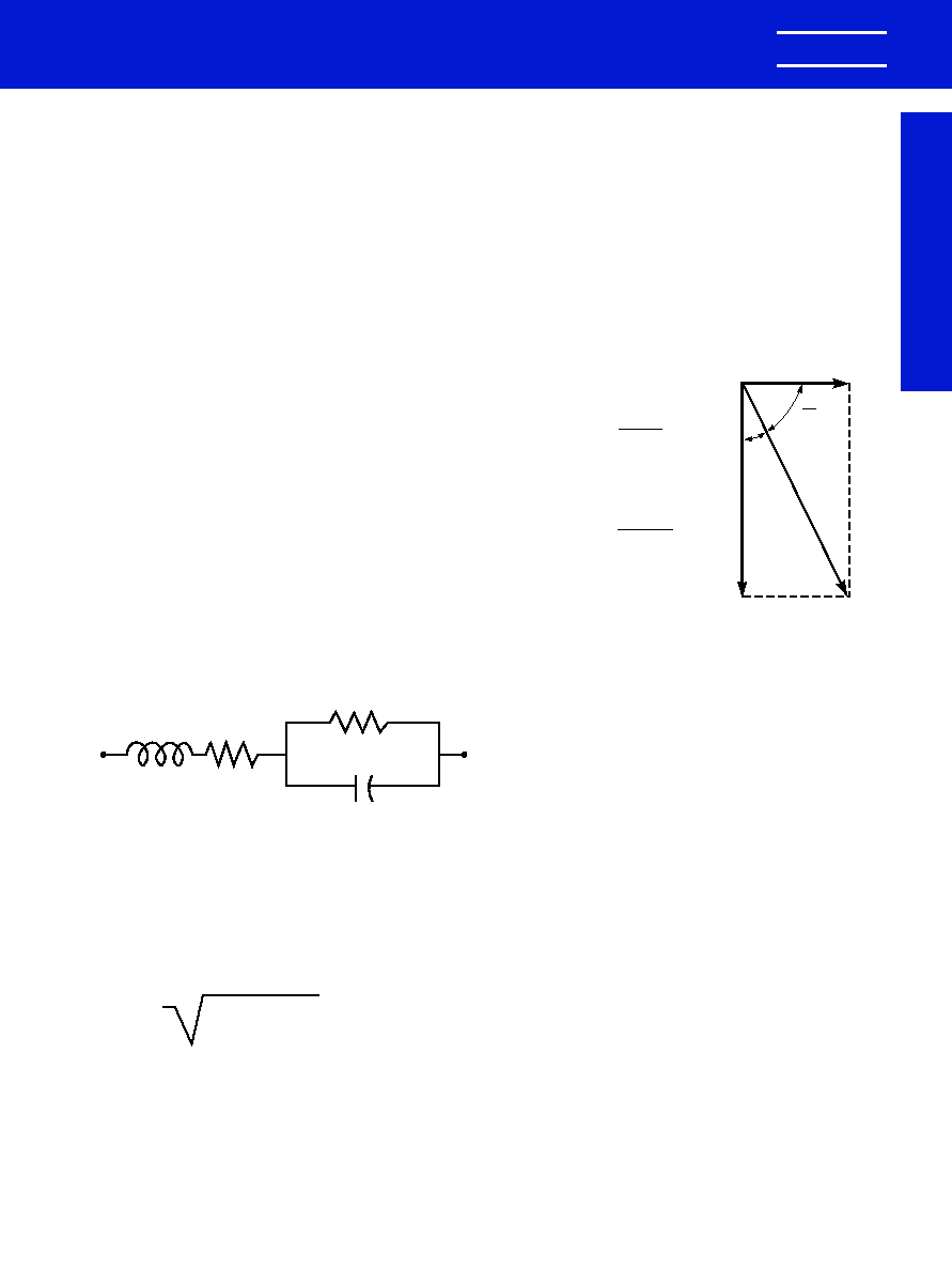
KEMET Electronics Corporation, P.O. Box 5928, Greenville, S.C. 29606, (864) 963-6300
35
APPLICATION NOTES FOR MULTILAYER CERAMIC CAPACITORS
Application Notes
ELECTRICAL CHARACTERISTICS
The fundamental electrical properties of multilayer
ceramic capacitors are as follows:
Polarity: Multilayer ceramic capacitors are not polar,
and may be used with DC voltage applied in either direction.
Rated Voltage: This term refers to the maximum con-
tinuous DC working voltage permissible across the entire
operating temperature range. Multilayer ceramic capacitors
are not extremely sensitive to voltage, and brief applications
of voltage above rated will not result in immediate failure.
However, reliability will be reduced by exposure to sustained
voltages above rated.
Capacitance: The standard unit of capacitance is the
farad. For practical capacitors, it is usually expressed in
microfarads (10
-6
farad), nanofarads (10
-9
farad), or picofarads
(10
-12
farad). Standard measurement conditions are as
follows:
Class I (up to 1,000 pF):
1MHz and 1.2 VRMS
maximum.
Class I (over 1,000 pF):
1kHz and 1.2 VRMS
maximum.
Class II:
1 kHz and 1.0 � 0.2 VRMS.
Class III:
1 kHz and 0.5 � 0.1 VRMS.
Like all other practical capacitors, multilayer ceramic
capacitors also have resistance and inductance. A simplified
schematic for the equivalent circuit is shown in Figure 1.
Other significant electrical characteristics resulting from
these additional properties are as follows:
Impedance: Since the parallel resistance (Rp) is nor-
mally very high, the total impedance of the capacitor is:
Figure 1
C = Capacitance
L = Inductance
R
S
= Equivalent Series Resistance (ESR)
R
P
= Insulation Resistance (IR)
R
P
R
S
C
L
Z =
R
S
+ (X
C
- X
L
)
2
2
Where
Z = Total Impedance
RS = Equivalent Series Resistance
X
C
= Capacitive Reactance = 1/(2
fC)
X
L
= Inductive Reactance = 2
fL
DF = ESR
Xc
Xc
2
fC
1
(ohm)
=
Figure 2
O
X
c
ESR
The variation of a capacitor's impedance with frequency
determines its effectiveness in many applications.
Dissipation Factor: Dissipation Factor (DF) is a mea-
sure of the losses in a capacitor under AC application. It is the
ratio of the equivalent series resistance to the capacitive reac-
tance, and is usually expressed in percent. It is usually mea-
sured simultaneously with capacitance, and under the same
conditions. The vector diagram in Figure 2 illustrates the rela-
tionship between DF, ESR, and impedance. The reciprocal of
the dissipation factor is called the "Q", or quality factor. For
convenience, the "Q" factor is often used for very low values
of dissipation factor. DF is sometimes called the "loss tangent"
or "tangent ", as derived from this diagram.
Insulation Resistance: Insulation Resistance (IR) is the
DC resistance measured across the terminals of a capacitor,
represented by the parallel resistance (Rp) shown in Figure 1.
For a given dielectric type, electrode area increases with
capacitance, resulting in a decrease in the insulation resis-
tance. Consequently, insulation resistance is usually specified
as the "RC" (IR x C) product, in terms of ohm-farads or
megohm-microfarads. The insulation resistance for a specific
capacitance value is determined by dividing this product by
the capacitance. However, as the nominal capacitance values
become small, the insulation resistance calculated from the
RC product reaches values which are impractical.
Consequently, IR specifications usually include both a mini-
mum RC product and a maximum limit on the IR calculated
from that value. For example, a typical IR specification might
read "1,000 megohm-microfarads or 100 gigohms, whichever
is less."
Insulation Resistance is the measure of a capacitor to
resist the flow of DC leakage current. It is sometimes referred
to as "leakage resistance." The DC leakage current may be
calculated by dividing the applied voltage by the insulation
resistance (Ohm's Law).
Dielectric Withstanding Voltage: Dielectric withstand-
ing voltage (DWV) is the peak voltage which a capacitor is
designed to withstand for short periods of time without dam-
age. All KEMET multilayer ceramic capacitors will withstand a
test voltage of 2.5 x the rated voltage for 60 seconds.
KEMET specification limits for these characteristics at
standard measurement conditions are shown in Table 1 on
page 4. Variations in these properties caused by changing
conditions of temperature, voltage, frequency, and time are
covered in the following sections.
KEMET
�
0988 Layout rev 8/9/2000 9:54 AM Page 35
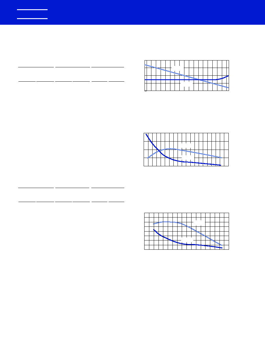
EFFECT OF TEMPERATURE
-20
-40
0
140
40
60
100
120
-60
20
80
%DF
0.0
2.0
4.0
6.0
8.0
Temperature
�
C
Capacitance & DF vs Temperature - X7R
Figure 4.
Temperature
�
C
Capacitance & DF vs Temperature - Z5U
Figure 5.
%DF
0
-10
-20
-30
-40
-50
-60
-70
-80
0
2.0
4.0
6.0
8.0
0.10
0.20
0.0
%DF
-55
-20
20
80
Temperature
�
C
Capacitance & DF vs Temperature - C0G
Figure 3.
-40
0
125
40
60
100
120
-0.1
0
+0.2
-0.2
+0.1
-0.1
0
+0.2
-0.2
+0.1
-20
-10
0
+20
+10
-60
-40
-20
+20
0
%
C
%
C
%DF
%
C
%
C
%DF
%
C
%
C
%DF
APPLICATION NOTES FOR MULTILAYER CERAMIC CAPACITORS
KEMET Electronics Corporation, P.O. Box 5928, Greenville, S.C. 29606, (864) 963-6300
36
KEMET
�
TABLE 1
EIA TEMPERATURE CHARACTERISTIC CODES
FOR CLASS I DIELECTRICS
Significant Figure
Multiplier Applied
Tolerance of
of Temperature
to Temperature
Temperature
Coefficient
Coefficient
Coefficient *
PPM per
Letter
Multi-
Number
PPM per
Letter
Degree C
Symbol
plier
Symbol
Degree C
Symbol
0.0
C
-1
0
�30
G
0.3
B
-10
1
�60
H
0.9
A
-100
2
�120
J
1.0
M
-1000
3
�250
K
1.5
P
-100000
4
�500
L
2.2
R
+1
5
�1000
M
3.3
S
+10
6
�2500
N
4.7
T
+100
7
7.5
U
+1000
8
+10000
9
* These symetrical tolerances apply to a two-point measurement of
temperature coefficient: one at 25�C and one at 85�C. Some deviation
is permitted at lower temperatures. For example, the PPM tolerance
for C0G at -55 is +30 / -72 PPM.
TABLE 2
EIA TEMPERATURE CHARACTERISTIC CODES
FOR CLASS II & III DIELECTRICS
Low Temperature
High Temperature Maximum Capacitance
Rating
Rating
Shift
Degree
Letter
Degree
Number
Letter
Celcius
Symbol
Celcius
Symbol
Percent
Symbol
+10C
Z
+45C
2
�1.0%
A
-30C
Y
+65C
4
�1.5%
B
-55C
X
+85C
5
�2.2%
C
+105C
6
�3.3%
D
+125C
7
�4.7%
E
+150C
8
�7.5%
F
+200C
9
�10.0%
P
�15.0%
R
�22.0%
S
�22 / -33%
T
�22 / -56%
U
�22 / -82%
V
0988 Layout rev 8/9/2000 9:54 AM Page 36
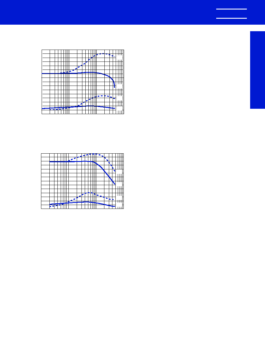
KEMET Electronics Corporation, P.O. Box 5928, Greenville, S.C. 29606, (864) 963-6300
37
KEMET
�
APPLICATION NOTES FOR MULTILAYER CERAMIC CAPACITORS
Application Notes
Effect of Temperature: Both capacitance and dissipa-
tion factor are affected by variations in temperature. The max-
imum capacitance change with temperature is defined by the
temperature characteristic. However, this only defines a "box"
bounded by the upper and lower operating temperatures and
the minimum and maximum capacitance values. Within this
"box", the variation with temperature depends upon the spe-
cific dielectric formulation. Typical curves for KEMET capaci-
tors are shown in Figures 3, 4, and 5. These figures also
include the typical change in dissipation factor for KEMET
capacitors.
Insulation resistance decreases with temperature.
Typically, the insulation resistance at maximum rated temper-
ature is 10% of the 25�C value.
Effect of Voltage: Class I ceramic capacitors are not
affected by variations in applied AC or DC voltages. For Class
II and III ceramic capacitors, variations in voltage affect only
the capacitance and dissipation factor. The application of DC
voltage higher than 5 vdc reduces both the capacitance and
dissipation factor. The application of AC voltages up to 10-20
Vac tends to increase both capacitance and dissipation factor.
At higher AC voltages, both capacitance and dissipation factor
begin to decrease.
Typical curves showing the effect of applied AC and DC
voltage are shown in Figure 6 for KEMET X7R capacitors and
Figure 7 for KEMET Z5U capacitors.
Effect of Frequency: Frequency affects both capaci-
tance and dissipation factor. Typical curves for KEMET multi-
layer ceramic capacitors are shown in Figures 8 and 9.
The variation of impedance with frequency is an impor-
tant consideration in the application of multilayer ceramic
capacitors. Total impedance of the capacitor is the vector of the
capacitive reactance, the inductive reactance, and the ESR, as
illustrated in Figure 2. As frequency increases, the capacitive
reactance decreases. However, the series inductance (L)
shown in Figure 1 produces inductive reactance, which
increases with frequency. At some frequency, the impedance
ceases to be capacitive and becomes inductive. This point, at
the bottom of the V-shaped impedance versus frequency
curves, is the self-resonant frequency. At the self-resonant fre-
quency, the reactance is zero, and the impedance consists of
the ESR only.
Typical impedance versus frequency curves for KEMET
multilayer ceramic capacitors are shown in Figures 10, 11, and
12. These curves apply to KEMET capacitors in chip form, with-
out leads. Lead configuration and lead length have a significant
impact on the series inductance. The lead inductance is
approximately 10nH/inch, which is large compared to the
inductance of the chip. The effect of this additional inductance
is a decrease in the self-resonant frequency, and an increase
in impedance in the inductive region above the self-resonant
frequency.
Effect of Time: The capacitance of Class II and III
dielectrics change with time as well as with temperature, volt-
age and frequency. This change with time is known as "aging."
It is caused by gradual realignment of the crystalline structure
of the ceramic dielectric material as it is cooled below its Curie
temperature, which produces a loss of capacitance with time.
The aging process is predictable and follows a logarithmic
decay. Typical aging rates for C0G, X7R, and Z5U dielectrics
are as follows:
C0G
None
X7R
1.0% per decade of time
Z5U
5.0% per decade of time
Typical aging curves for X7R and Z5U dielectrics are
shown in Figure 13.
The aging process is reversible. If the capacitor is heat-
ed to a temperature above its Curie point for some period of
time, de-aging will occur and the capacitor will regain the
capacitance lost during the aging process. The amount of de-
aging depends on both the elevated temperature and the
length of time at that temperature. Exposure to 150�C for one-
half hour or 125�C for two hours is usually sufficient to return
the capacitor to its initial value.
Because the capacitance changes rapidly immediately
after de-aging, capacitance measurements are usually delayed
for at least 10 hours after the de-aging process, which is often
referred to as the "last heat." In addition, manufacturers utilize
EFFECT OF APPLIED VOLTAGE
0.1
1
10
100
AC or DC Volts Applied
Typical Effects of 1000 Hz AC and DC Voltage Level on
Capacitance and Dissipation Factor - Z5U
Note: C0G Dielectric capacitance and dissipation factor are
stable with voltage.
Figure 7.
1
2
3
4
+20
0
-20
-40
-60
1
2
3
4
+10
+5
0
-5
-10
0.1
1
10
100
AC or DC Volts Applied
Typical Effects of 1000 Hz AC and DC Voltage Level on
Capacitance and Dissipation Factor - X7R
Note: C0G Dielectric capacitance and dissipation factor are
stable with voltage.
Figure 6.
DC
AC
AC
DC
% D.F
.
% Capacitance Change
% D.F
.
% Capacitance Change
DC
AC
AC
DC
0988 Layout rev 8/9/2000 9:54 AM Page 37
APPLICATION NOTES FOR MULTILAYER CERAMIC CAPACITORS
KEMET Electronics Corporation, P.O. Box 5928, Greenville, S.C. 29606, (864) 963-6300
38
KEMET
�
the aging rates to set factory test limits which will bring the
capacitance within the specified tolerance at some future time,
to allow for customer receipt and use. Typically, the test limits
are adjusted so that the capacitance will be within the specified
tolerance after either 1,000 hours or 100 days, depending on
the manufacturer and the product type.
POWER DISSIPATION
Power dissipation has been empirically determined for
two representative KEMET series: C052 and C062. Power dis-
sipation capability for various mounting configurations is shown
in Table 3. This table was extracted from Engineering Bulletin
F-2013, which provides a more detailed treatment of this sub-
ject.
Note that no significant difference was detected between
the two sizes in spite of a 2 to 1 surface area ratio. Due to the
materials used in the construction of multilayer ceramic capac-
itors, the power dissipation capability does not depend greatly
on the surface area of the capacitor body, but rather on how
well heat is conducted out of the capacitor lead wires.
Consequently, this power dissipation capability is applicable to
other leaded multilayer styles and sizes.
TABLE 3
POWER DISSIPATION CAPABILITY
(Rise in Celsius degrees per Watt)
Power
Mounting Configuration
Dissipation
of C052 & C062
1.00" leadwires attached to binding post
90 Celsius degrees
of GR-1615 bridge (excellent heat sink)
rise per Watt �10%
0.25" leadwires attached to binding post
55 Celsius degrees
of GR-1615 bridge
rise per Watt �10%
Capacitor mounted flush to 0.062" glass-
77 Celsius degrees
epoxy circuit board with small copper traces
rise per Watt �10%
Capacitor mounted flush to 0.062" glass-
53 Celsius degrees
epoxy circuit board with four square inches
rise per Watt �10%
of copper land area as a heat sink
As shown in Table 3, the power dissipation capability of
the capacitor is very sensitive to the details of its use environ-
ment. The temperature rise due to power dissipation should not
exceed 20�C. Using that constraint, the maximum permissible
power dissipation may be calculated from the data provided in
Table 3.
It is often convenient to translate power dissipation capa-
bility into a permissible AC voltage rating. Assuming a sinu-
soidal wave form, the RMS "ripple voltage" may be calculated
from the following formula:
The data necessary to make this calculation is included in
Engineering Bulletin F-2013. However, the following criteria
must be observed:
1. The temperature rise due to power dissipation
should be limited to 20�C.
2. The peak AC voltage plus the DC voltage must not
exceed the maximum working voltage of the
capacitor.
Provided that these criteria are met, multilayer ceramic
capacitors may be operated with AC voltage applied without
need for DC bias.
RELIABILITY
A well constructed multilayer ceramic capacitor is
extremely reliable and, for all practical purposes, has an infi-
nite life span when used within the maximum voltage and
temperature ratings. Capacitor failure may be induced by sus-
tained operation at voltages that exceed the rated DC voltage,
voltage spikes or transients that exceed the dielectric with-
standing voltage, sustained operation at temperatures above
the maximum rated temperature, or the excessive tempera-
ture rise due to power dissipation.
Failure rate is usually expressed in terms of percent per
1,000 hours or in FITS (failure per billion hours). Some
KEMET series are qualified under U.S. military established
reliability specifications MIL-PRF-20, MIL-PRF-123, MIL-
PRF-39014, and MIL-PRF-55681. Failure rates as low as
0.001% per 1,000 hours are available for all capacitance /
voltage ratings covered by these specifications. These spec-
ifications and accompanying Qualified Products List should
be consulted for details.
For series not covered by these military specifications,
an internal testing program is maintained by KEMET Quality
Assurance. Samples from each week's production are sub-
jected to a 2,000 hour accelerated life test at 2 x rated voltage
and maximum rated temperature. Based on the results of
these tests, the average failure rate for all non-military series
covered by this test program is currently 0.06% per 1,000
hours at maximum rated conditions. The failure rate would be
much lower at typical use conditions. For example, using MIL-
HDBK-217D this failure rate translates to 0.9 FITS at 50%
rated voltage and 50�C.
Current failure rate details for specific KEMET multilay-
er ceramic capacitor series are available on request.
MISAPPLICATION
Ceramic capacitors, like any other capacitors, may fail
if they are misapplied. Typical misapplications include expo-
sure to excessive voltage, current or temperature. If the
dielectric layer of the capacitor is damaged by misapplication
the electrical energy of the circuit can be released as heat,
which may damage the circuit board and other components
as well.
If potential for misapplication exists, it is recommended
that precautions be taken to protect personnel and equipment
during initial application of voltage. Commonly used precau-
tions include shielding of personnel and sensing for excessive
power drain during board testing.
E = Z
Where
E = RMS Ripple Voltage (volts)
P = Power Dissipation (watts)
Z = Impedence
R = ESR
P
R
0988 Layout rev 8/9/2000 9:54 AM Page 38
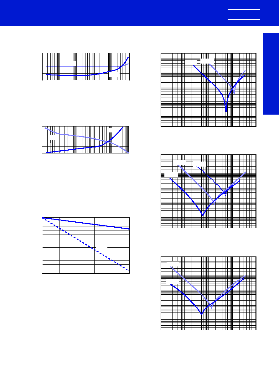
KEMET Electronics Corporation, P.O. Box 5928, Greenville, S.C. 29606, (864) 963-6300
39
KEMET
�
APPLICATION NOTES FOR MULTILAYER CERAMIC CAPACITORS
Application Notes
IMPEDANCE VS FREQUENCY
Impedance (Ohms)
1
10
100
1,000
0.001
0.01
1
10
100
0.1
0.1
Frequency - MHz
Impedance vs Frequency for C0G Dielectric
Figure 10.
EFFECT OF FREQUENCY
-0.1
0
+0.2
-0.2
+0.1
0.10
0.20
0.0
Frequency - Hertz
Capacitance & DF vs Frequency - C0G
Figure 8.
%DF
Typical Aging Rates for X7R & Z5U
Figure 13.
74%
76%
78%
80%
82%
84%
86%
88%
90%
92%
94%
96%
98%
100%
Capacitance
1
10
100
1000
10K
100K
EFFECT OF TIME
%DF
-10
-5
+5
-15
0
5.0
10.0
0.0
2.5
7.5
Frequency - Hertz
Capacitance & DF vs Frequency - X7R & Z5U
Figure 9.
.01
�
F
.001
�
F
%
C
100
1K
10K
100K
1M
10M
100
1K
10K
100K
1M
10M
%
C
%
C
%DF
Z5U
X7R
%DF
%
C
Impedance (Ohms)
1
10
100
1,000
0.001
0.01
1
10
100
0.1
0.1
Frequency - MHz
Impedance vs Frequency for Z5U Dielectric
Figure 12.
Impedance (Ohms)
1
10
100
1,000
0.001
0.01
1
10
100
0.1
0.1
Frequency - MHz
Impedance vs Frequency for X7R Dielectric
Figure 11.
0.1
�
F
1.0
�
F
0.1
�
F
.01
�
F
1.0
�
F
0988 Layout rev 8/9/2000 9:54 AM Page 39

KEMET
Electronics Corporation
�
World Sales Headquarters
P.O. Box 5928 � Greenville, SC 29606 � www.kemet.com
Phone: (864) 963-6300 � Fax: (864) 963-6521
KEMET Electronics Corporation
26 Corporate Plaza, Suite 170
Newport Beach, CA 92660
Phone: 949-640-9320
Fax: 949-720-9807
KEMET Electronics Corporation
2359 Mission College Blvd., Suite 390
Santa Clara, CA 95054
Phone: 408-986-0424
Fax: 408-986-1442
KEMET Electronics Corporation
Schaumburg Corporate Center
Suite 350, 1515 Woodfield Road
Schaumburg, IL 60173
Phone: 847-517-1030
Fax: 847-517-1037
KEMET Electronics Corporation
301 Edgewater Place, Suite 208
Wakefield, MA 01880
Phone: 781-245-4646
Fax: 781-245-1595
KEMET Electronics Corporation
Piedmont Center East, Suite 410
B-137, 37 Villa Road
Greenville, SC 29615
Phone: 864-242-5789
Fax: 864-242-5795
KEMET Electronics Corporation
8445 Freeport Parkway, Suite 320
Irving, TX 75063
Phone: 972-870-9530
Fax: 972-870-9537
KEMET Electronics Canada Ltd.
105-7145 West Credit Ave., Bldg. #2
Mississauga, L5N 6J7, ON
Canada
Phone: 905-542-7930
Fax: 905-542-7949
KEMET Electronics Canada Ltd.
65 boul. Brunswick, Suite 214
Dollard-des-Ormeaux, QC
Canada
Phone: 514-685-3773
Fax: 514-685-4077
USA/Canada Locations
KEMET Electronics S.A.R.L.
2, Rue Nicolas Ledoux
Silic 254
94568 Rungix Cedex
France
Phone: 33-1-4512-5320
Fax: 33-1-4687-4087
KEMET Electronics GmbH
Postfach 1380
D85531 Haar/Munich
Germany
Phone: 49-89-456-4200
Fax: 49-89-460-4117
KEMET Electronics S.A.
1-3, Avenue de la Paix
P.O.B. 76
CH-1211 Geneva 20,
Switzerland
Phone: 41-22-715-0100
Fax: 41-22-715-0170
KEMET Electronics Ltd.
Waterfront House, 55/61 South St.
Bishop's Stortford
Hertfordshire, CM23 3AL
United Kingdom
Phone: 44-1279-75-7343
Fax: 44-1279-75-7188
Aviv Electronics Ltd.
Hayetzira St. No. 4
P.O. Box 2433
Ra'anana, 43100
Israel
Phone: 972-9-748-3232
Fax: 972-9-741-6510
Multitech Electronics Corporation PTY
P.O. Box 23351
Claremont 7735, South Africa
Phone: 27-21-64-4103
Fax: 27-21-64-1360
Arrow Altech Distribution PTY LTD
53 - 57 Yaldwyn Road
Hughes Ext.
Jet Park 1459
South Africa
Phone: 27-11-923-9600
Fax: 27-11-923-9884
Europe/Africa Locations
KEMET Electronics (Shanghai) Co., Ltd.
2/F, No. 7 Bldg., 330 Xlya Rd.
Waigaoqiao Free Trade Zone
Pudong, Shanghai 200137, China
Phone: 86-21-5046-0983
Fax: 86-21-5046-0981
KEMET Electronics Asia Ltd.
(Beijing Representative Office)
Suite 1512, 15/F, Lucky Tower B
3 Dong San Huan Bei Rd., Chao Yang District
Beijing, 100027, China
Phone: 86-10-6462-0173
Fax: 86-10-6461-5707
KEMET Electronics Asia Ltd.
4A Chuan Hing Industrial Bldg.
14 Wang Tai Road
Kowloon Bay, Hong Kong
Phone: 852-2305-1168
Fax: 852-2759-0345
KEMET Electronics Marketing PTE Ltd.
8-2-04, Sunny Point Kompleks, Jalan
Batu Uban, 11700 Penang
Penang, Malaysia
Phone: 60-4-6595200
Fax: 60-4-6595220
KEMET Electronics Marketing PTE Ltd.
101 Thomson Road, #23-03
United Square
Singapore, 307591, Singapore
Phone: 65-353-6636
Fax: 65-353-6656
KEMET Electronics Corporation
Taiwan Branch, 3-4F, No. 148, Section 4
Chung-Hsaio E. Rd.
Taipei, Taiwan ROC
Phone: 886-2-27528585
Fax: 886-2-27213129
Bestrade Limited
28/3 Charoren Vian Road Sllcom
Bangrak, Bangkok 10500, Thailand
Phone: 662-235-1613
Fax: 662-237-7132
Crusader Electronics Pty. Ltd.
Unit 3, 92 Bryant Street
Padstow, NSW 2211, Australia
Phone: 02-9792-3922
Fax: 02-9792-1446
Electronic Enterprises Private Ltd.
Post Bag No. 6367
Unit 216 Regal Industrial Estate
Acharya Donde Marg., Sewri
Bombay 400 015, India
Phone: 91-22-413-7096
Fax: 91-22-413-3341
Unicom International Corporation
702 Shinhwa Bldg., Mapo-Gu
Seoul, 121050, Korea
Phone: 82-2712-5821
Fax: 82-2712-5823
Asia Locations
NOTICE: Place 011 in front of the above Phone and Fax numbers for Europe and Asia, when dialing from a United States exchange.
Note: KEMET reserves the right to modify minor details of internal and external construction at any time in the interest of product improvement.
KEMET does not assume any responsibility for infringement that might result from the use of KEMET Capacitors in potential circuit designs.
"KEMET" is a registered trademark of KEMET Electronics Corporation.
03/00
0988 Layout rev 8/9/2000 9:54 AM Page 40