Notes:
TM
TM
23105 KASHIWA COURT
23105 KASHIWA COURT
TORRANCE, CA 90505
TORRANCE, CA 90505
R
WARM WHITE
EMISSION COLOR
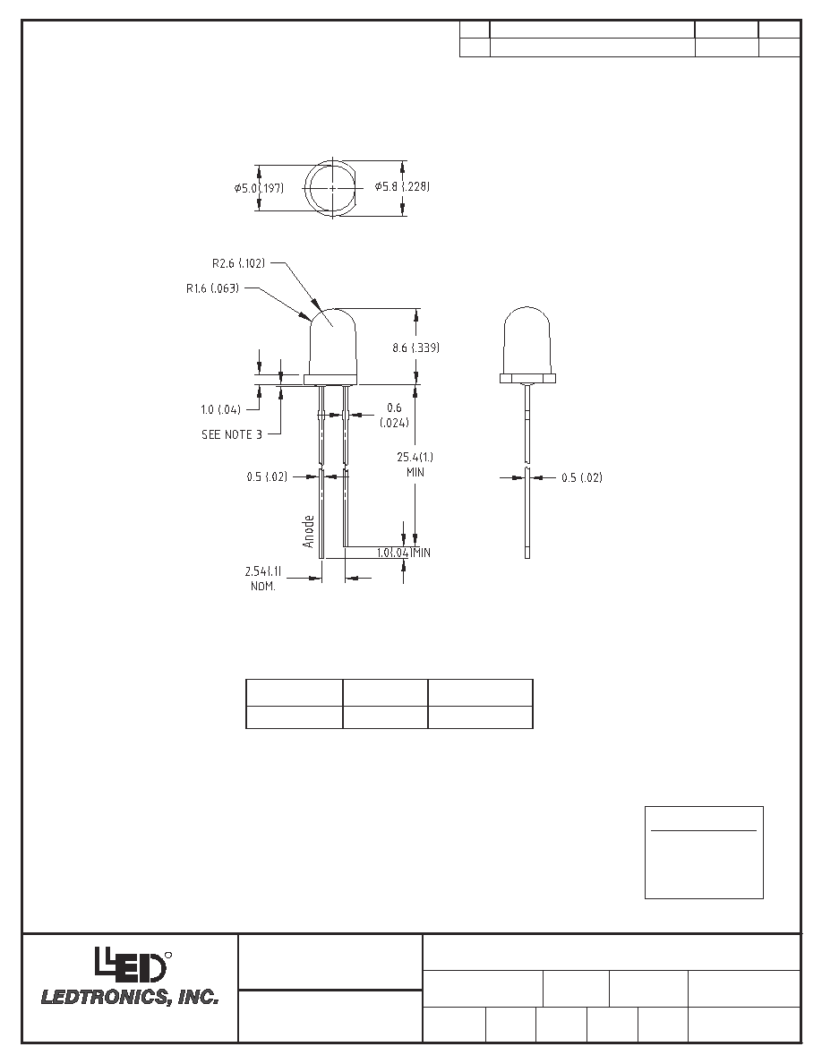
4. LEAD SPACING IS MEASURED WHERE LEADS EMERGE FROM THE PACKAGE.
REQUIREMENTS OF MIL-STD-202, METHOD 208.
LEADS TO BE SOLDERABLE AND CAPABLE OF MEETING THE SOLDERABILITY
MANUFACTURE DATE SHALL NOT BE OLDER THAN 26 WEEKS (6 MONTHS).
6.
5.
PROTRUDED RESIN UNDER FLANGE IS 1.0mm (.04") MAX.
ALL DIMS ARE IN MILLIMETERS (INCHES).
TOLERANCE IS ±0.25mm (±.010") UNLESS OTHERWISE SPECIFIED.
3.
2.
1.
WATER CLEAR
InGaN
LENS COLOR
CHIP MATERIAL
ELECTROSTATIC
SENSITIVE
DEVICES
OBSERVE PRECAUTIONS
FOR HANDLING-
DSDC302
8Z410
TM
LEDTRONICS, INC.
-PROPRIETARY-
LEDTRONICS, INC.
It may not be copied, used or disclosed
This document contains Proprietary
(UNLESS OTHERWISE STATED)
TOLERANCE PER ANSI-Y14.5
for any purpose without the prior express
ANGLES ± 0∞,30'
FRACT. ± 1/32
.XXX ± .010
written consent of
information of
.XX ± .025
TM
CODE
IDENT NO.
DWG NO
TITLE
11-23-05
RM
SHEET
L200-0WW-20D
SCALE
CHK BY
DWG BY
2:1
QA
3
OF
1
MNFG
CUSTOMER
DATE
ATTENTION
LTR
C
12-13-05
REVISION
DATE
APPD
RM
12-16-05
PL
12-16-05
GZ
Continuous Forward Current
Body]
[4mm (.157
m
e
T
perature
Lead Soldering
) From
50∞C
perature Range
mperature Range
Electrostatic Discharge (ESD)
e
T
Operating
orage
St
e
T
m
oltage
Derating Linear From
Reverse V
eter
(1/10 Duty Cycle, 0.1ms Pulse
Absolute Maximum Ratings at Ta 25∞C
Peak Forward Current
Power Dissipation
Param
Width
mA
20
260∞C for 5 Seconds
mA/∞C
-30∞C to +100∞C
-20∞C to +80∞C
150
V
0.4
5
V
100
80
mA
mW
MAX.
Unit
Luminous intensity is measured with a light sensor and filter combination that approximates
is the off-axis at which the luminous intensity is half the axial luminous intensity.
3. Forward voltage measurement allowance is ±0.1V
Luminous intensity measurement allowance is ±10%
4.
Notes:
the CIE eye-response curve.
2.
1
Bin Lim
Lower Right
T
Color Rank
Radiant Intensity
Forward V
Reverse Current
ewing Angle
BIN C
BIN D
Lumens
SCP
i
V
---
---
---
Lower Left
1/2
1/2
0.27
0.29
x
ltage
o
I
R
V
f
2
---
0.29
0.32
y
0.29
0.32
x
---
---
---
2.8
12
Luminous Intensity
Param
rical Optical Characteristics at
Elect
bol
ter
e
Sym
I
v
Min.
Upper Left
=20mA
=5V
(Note
Upper Right
y coordinates)
---
ts (CIE1931
0.26
0.30
y
i
0.26
0.29
x,
x
---
3.5
17
50
---
---
4.0
22
uW/sr
0.23
0.26
y
0.25
0.27
x
uA
---
---
V
Deg
V
R
I
f
---
0.25
0.29
y
---
---
2)
=20mA
Condition
=25∞C
a
7500
yp.
T
---
Max.
m
Unit
d
c
T
f
I
st
e
(Note 1)
1.67
28673
.13
---
TM
TM
23105 KASHIWA COURT
23105 KASHIWA COURT
TORRANCE, CA 90505
TORRANCE, CA 90505
R
QA
L200-0WW-20D
for any purpose without the prior express
LEDTRONICS, INC.
TOLERANCE PER ANSI-Y14.5
(UNLESS OTHERWISE STATED)
written consent of
.XXX ± .010
FRACT. ± 1/32
.XX ± .025
ANGLES ± 0∞,30'
IDENT NO.
DSDC302-A
TM
8Z410
CODE
DWG NO
RM
DWG BY
SCALE
CHK BY
NTS
-PROPRIETARY-
LEDTRONICS, INC.
This document contains Proprietary
It may not be copied, used or disclosed
information of
TM
TITLE
CUSTOMER
11-23-05
3
MNFG
SHEET
2 OF
DATE
REVISION
LTR
C
APPD
DATE
12-13-05
RM
(UNLESS OTHERWISE STATED)
TOLERANCE PER ANSI-Y14.5
for any purpose without the prior express
information of
It may not be copied, used or disclosed
This document contains Proprietary
ANGLES ± 0∞,30'
.XX ± .025
FRACT. ± 1/32
.XXX ± .010
written consent of
LEDTRONICS, INC.
-PROPRIETARY-
LEDTRONICS, INC.
TM
TM
L200-0WW-20D
CHK BY
RM
8Z410
DSDC302-B
IDENT NO.
DWG NO
CODE
TITLE
DWG BY
NTS
SCALE
QA
SHEET
3
MNFG
OF 3
11-23-05
CUSTOMER
DATE
REVISION
LTR
C
APPD
DATE
12-13-05
RM
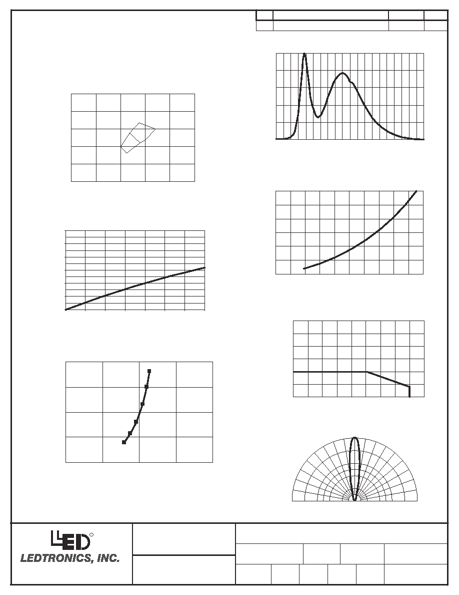
Typical Electrical / Optical Characteristics Curves
(25∞C Ambient Temperature Unless Otherwise Noted)
Forward Current
vs. Derating curve
0
10
20
30
40
50
60
0
1 0
20
40
50
60
70
0
8
90
0.25
0.26
0.27
0.28
0.24
0.25
0.26
0.27
0.28
0.29
x
y
10mA
20mA
30mA
Forward Current vs.
Chromaticity Coordinates
Spectral Radiance
0 0
0 2
0 4
0 6
0 8
1 0
3 80
420
460
5 00
540
580
6 20
660
700
7 40
780
Wavelength (nm)
0
3
Forward Current
vs. Forward voltage
0
5
10
15
20
25
30
2.5
2 .75
3.0
3.25
3.5
3.75
Relative Luminous Intensity
vs. Forward Current
0
1
2
0
5
0
15
20
25
30
35
Forward Current If (mA)
Relative Intensity (LOP@20mA=1)
40mA
5mA
1mA
Ta = 25∞C
CIE 1931 Chromaticity Diagram
C
D
0.40
0.35
0.30
0.25
0.20
0.15
0.15
0.20
0.25
0.30
0.35
0.40
Forward Current
If (mA)
Forward Voltage Vf (V)
Forward Current
If (mA)
Derating Curve Ta (∞C)
Normalized
Response
X
Y
60∞
90∞
30∞
-60∞
-90∞
-30∞
0∞
Beam Pattern
Rela
6
0.
1.0
0.
.4
8
6
0.
1.0
8
0.
0.2
0.
0.4
2
0
X
y (LO
Inte
tive
nsit
A
P@M
=1)
TM
23105 KASHIWA COURT
TORRANCE, CA 90505
R