FEATURES
Direct Replacement For SILICONIX DPAD SERIES
HIGH ON ISOLATION
20fA
EXCELLENT CAPACITANCE MATCHING
C
R
0.2pF
ABSOLUTE MAXIMUM RATINGS
1
@ 25 ∞C (unless otherwise stated)
Maximum Temperatures
Storage Temperature
-65 to +150 ∞C
Operating Junction Temperature
-55 to +135 ∞C
Maximum Power Dissipation
Continuous Power Dissipation (DPAD)
500mW
Maximum Currents
Forward Current (DPAD)
50mA
COMMON ELECTRICAL CHARACTERISTICS @ 25 ∞C (unless otherwise stated)
SYMBOL
CHARACTERISTIC
MIN TYP MAX UNITS CONDITIONS
DPAD1 -45
DPAD2,5,10,20,50,100
-45
BV
R
Reverse Breakdown
Voltage
SSTDPAD5,50,100 -30
I
R
= -1µA
V
F
Forward
Voltage
0.8
1.5
V
I
F
= 1mA
DPAD1
0.2
|C
R1
-C
R2
|
Differential Capacitance
(C
R
)
ALL OTHERS
0.5
V
R1
= V
R2
= -5V, f = 1MHz
DPAD1
0.8
DPAD2,5,10,20,50,100
2.0
C
rss
Total Reverse Capacitance
SSTDPAD5,50,100 4.0
pF
V
R
= -5V, f = 1MHz
SPECIFIC ELECTRICAL CHARACTERISTICS @ 25 ∞C (unless otherwise stated)
SYMBOL CHARACTERISTIC
DPAD
2
SSTDPAD
2
UNITS
CONDITIONS
(SST)DPAD1
-1
(SST)DPAD2
-2
(SST)DPAD5
-5 -5
(SST)DPAD10
-10
(SST)DPAD20
-20
(SST)DPAD50
-50 -50
I
R
Maximum Reverse
Leakage Current
2
(SST)DPAD100
-100 -100
pA V
R
= -20V
SSTDPAD
1
2
3
4
8
7
6
5
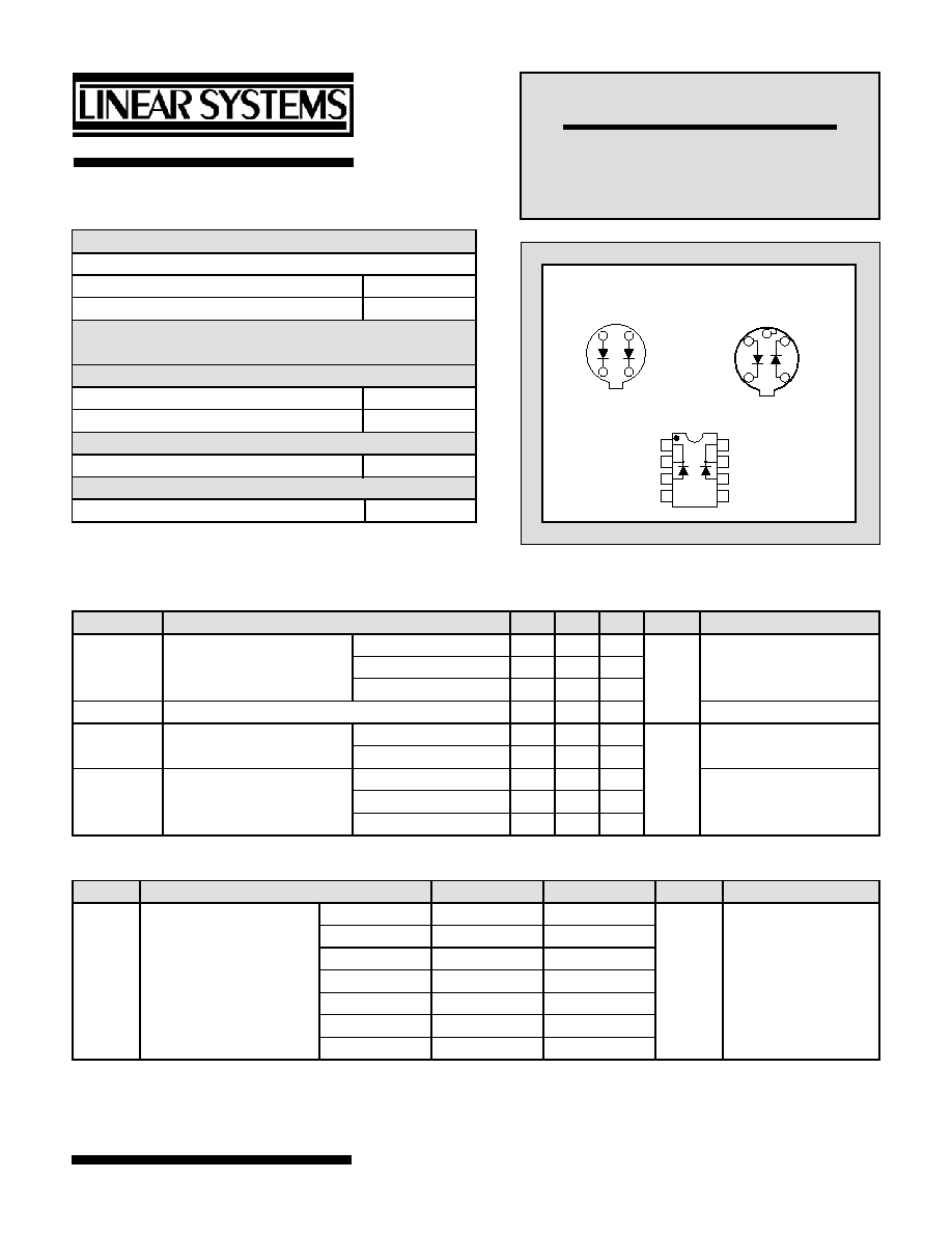
SOIC
K1
K1
A1
NC
K2
K2
A2
NC
DPAD1
A1
K1
K2
A2
5
BOTTOM VIEW
TO-78
1
3
4
7
C
DPAD
A1
K1
A2
K2
3
1
7
5
BOTTOM VIEW
TO-72
Linear Integrated Systems
DPAD SERIES
MONOLITHIC DUAL
PICO AMPERE DIODES
Linear Integrated Systems
∑ 4042 Clipper Court ∑ Fremont, CA 94538 ∑ Tel: 510 490-9160 ∑ Fax: 510 353-0261

Figure 1. Operational Amplifier Protection
Input Differential Voltage limited to 0.8V (typ) by DPADs D
1
and D
2
. Common
Mode Input voltage limited by DPADs D
3
and D
4
to ±15V.
Figure 2. Sample and Hold Circuit
Typical Sample and Hold circuit with clipping. DPAD diodes reduce offset
voltages fed capacitively from the JFET switch gate.
FIGURE 1
FIGURE 2
2N4117A
R
2N4393
-V
+V
V
OUT
D2
D1
C
DPAD1
CONTROL
SIGNAL
e
in
+V
-15V
+15V
OP-27
D1
D2
D3
D4
+
-
DPAD10
1
SOIC
2
3
4
5
6
7
8
DIMENSIONS IN
INCHES
0.2284
0.2440
0.189
0.196
0.0075
0.0098
0.021
0.014
0.018
0.050
0.0040
0.0098
0.150
0.157
TO-78
0.335
0.370
0.305
0.335
0.016
0.019
0.165
0.185
0.040
MAX.
DIM. A
0.016
0.021
DIM. B
MIN. 0.500
0.200
0.100
0.100
0.028
0.034
45∞
1
3 4
5
7
0.029
0.045
SEATING
PLANE
TO-72
Four Lead
0.230
0.209
DIA.
DIA.
0.195
0.175
0.030
MAX.
0.500 MIN.
0.150
0.115
0.019
0.016
DIA.
4 LEADS
2
1
3
0.046
0.036
45∞
0.048
0.028
0.100
0.050
4
Linear Integrated Systems
∑ 4042 Clipper Court ∑ Fremont, CA 94538 ∑ Tel: 510 490-9160 ∑ Fax: 510 353-0261
1.
Absolute maximum ratings are limiting values above which serviceability may be impaired.
2.
The DPAD type number denotes its maximum reverse current value in pico amperes. Devices with I
R
values intermediate to those
shown are available upon request.
Information furnished by Linear Integrated Systems is believed to be accurate and reliable. However, no responsibility is assumed for its
use; nor for any infringement of patents or other rights of third parties which may result from its use. No license is granted by implicatio
otherwise under any patent or patent rights of Linear Integrated Systems.
n or