FEATURES
SECOND SOURCE FOR SILICONIX J500 SERIES
WIDE CURRENT RANGE
0.192 to 5.6mA
BIASING NOT REQUIRED
V
GS
= 0V
ABSOLUTE MAXIMUM RATINGS
1
@ 25 ∞C (unless otherwise stated)
Maximum Temperatures
Storage Temperature
-55 to 150∞C
Junction Operating Temperature
-55 to 135∞C
Maximum Power Dissipation
Continuous Power Dissipation @125∞C
360mW
Maximum Currents
Forward Current
20mA
Reverse Current
50mA
Maximum Voltages
Peak Operating Voltage
P
OV
= 50V
COMMON ELECTRICAL CHARACTERISTICS @ 25 ∞C (unless otherwise stated)
SYMBOL
CHARACTERISTIC
MIN TYP MAX UNITS
CONDITIONS
P
OV
Peak Operating Voltage
2
50
V
I
F
= 1.1I
F(max)
V
R
Reverse
Voltage
0.8 V I
R
= 1mA
C
F
Forward
Capacitance
2.2 pF V
F
= 25V, f = 1MHz
SPECIFIC ELECTRICAL CHARACTERISTICS @ 25 ∞C (unless otherwise stated)
Forward Current
3
I
F
Dynamic Impedance
4
Z
d
Knee
Impedance
Z
k
Limiting Voltage
5
V
L
V
F
= 25V
V
F
= 25V
V
F
= 6V
I
F
= 0.8I
F(min)
PART
MIN
NOM
MAX
MIN
TYP
TYP
TYP
MAX
J500 0.192 0.24 0.288 4.00 15 2.50 1.2 0.4
J501 0.264 0.33 0.396 2.20 10 1.60 1.3 0.5
J502 0.344 0.43 0.516 1.50 7 1.10 1.5 0.6
J503 0.448 0.56 0.672 1.20 5 0.80 1.7 0.7
J504 0.600 0.75 0.900 0.80 3.5 0.55 1.9 0.8
J505 0.800 1.00 1.200 0.50 2. 0.40 2.1 0.9
J506 1.120 1.40 1.680 0.33 1.5 0.25 2.5 1.1
J507 1.440 1.80 2.160 0.20 1 0.19 2.8 1.3
J508 1.900 2.40 2.900 0.20 0.7 0.13 3.1 1.5
J509 2.400 3.00 3.600 0.15 0.5 0.09 3.5 1.7
J510 2.900 3.60 4.300 0.15 0.4 0.07 3.9 1.9
J511 3.800 4.70 5.600 0.12 0.3 0.05 4.2 2.1
A
K
A
K
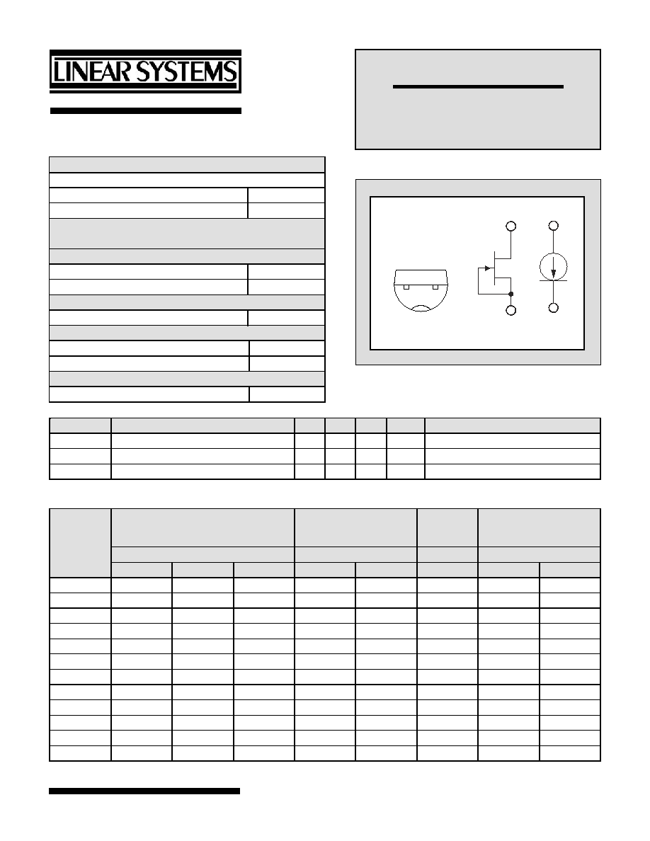
TO-92
BOTTOM VIEW
1
2
A
K
Linear Integrated Systems
J500 SERIES
CURRENT REGULATING
DIODES
Linear Integrated Systems
∑ 4042 Clipper Court ∑ Fremont, CA 94538 ∑ Tel: 510 490-9160 ∑ Fax: 510 353-0261
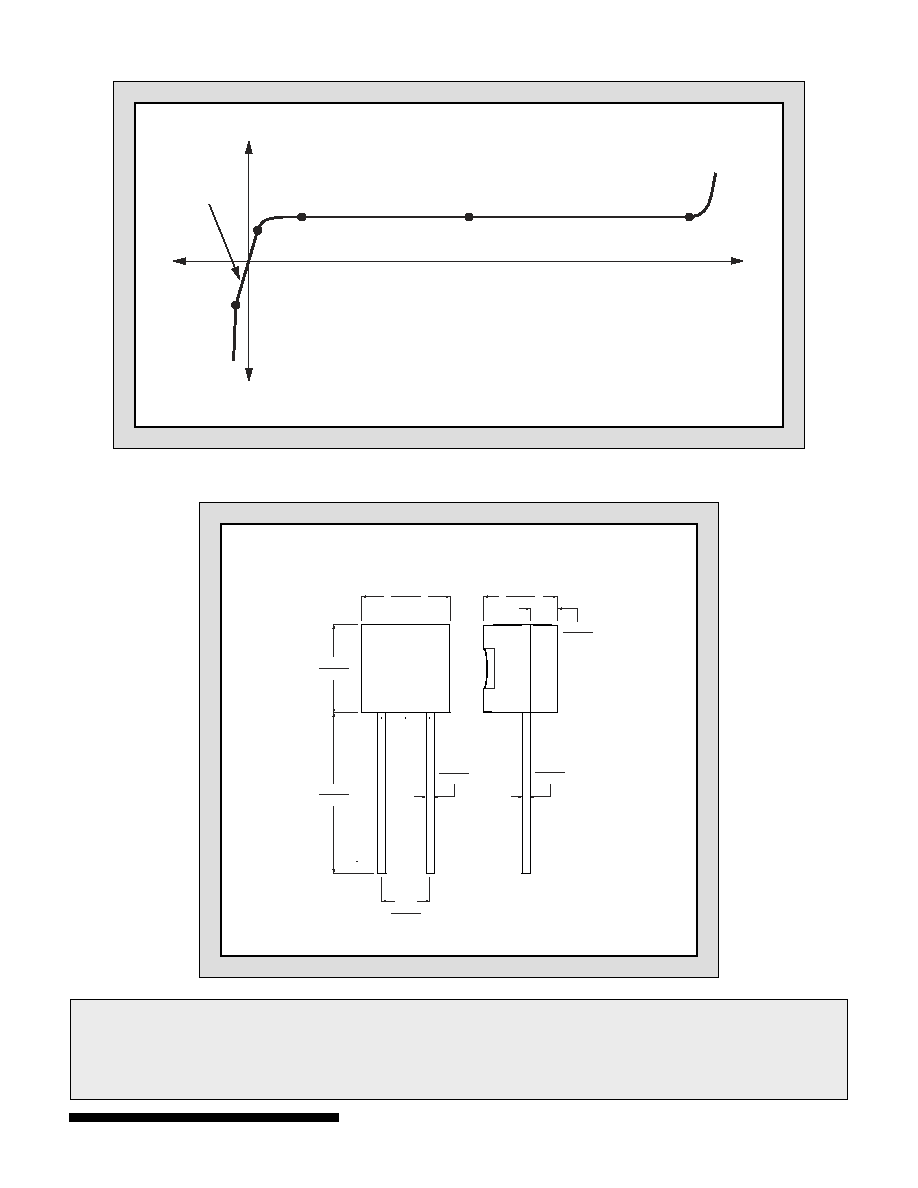
V-I CHARACTERISTICS CURRENT REGULTING DIODE
P
OV
I
F
Z
k
V
L
V
R
V
R
I
R
I
F
V
F
r
DS
PACKAGING DETAILS
1
2
LS XXX
YYWW
0.170
0.195
0.500
0.610
0.016
0.022
0.095
0.105
0.175
0.195
0.130
0.155
0.045
0.060
0.014
0.020
TO-92
DIMENSIONS
IN INCHES.
Linear Integrated Systems
∑ 4042 Clipper Court ∑ Fremont, CA 94538 ∑ Tel: 510 490-9160 ∑ Fax: 510 353-0261
1.
Absolute maximum ratings are limiting values above which serviceability may be impaired.
2.
Pulsed, t = 2ms. Maximum V
F
where I
F
< 1.1I
F(max)
.
3.
Pulsed, t = 2ms. Continuous currents may vary.
4.
Pulsed, t = 2ms. Continuous impedances may vary.
5. Min
V
F
required to ensure I
F
= 0.8I
F(min)
.
Information furnished by Linear Integrated Systems is believed to be accurate and reliable. However, no responsibility is assumed for its use; nor for any
infringement of patents or other rights of third parties which may result from its use. No license is granted by implication or otherwise under any patent or patent
rights of Linear Integrated Systems.