 | –≠–ª–µ–∫—Ç—Ä–æ–Ω–Ω—ã–π –∫–æ–º–ø–æ–Ω–µ–Ω—Ç: LT1097F01 | –°–∫–∞—á–∞—Ç—å:  PDF PDF  ZIP ZIP |
1
LT1097
Low Cost, Low Power
Precision Op Amp
FEATURES
DESCRIPTIO
N
U
s
Offset Voltage
50
µ
V Max
s
Offset Voltage Drift
1
µ
V/
∞
C Max
s
Bias Current
250pA Max
s
Offset Current
250pA Max
s
Bias and Offset Current Drift
4pA/
∞
C Max
s
Supply Current
560
µ
A Max
s
0.1Hz to 10Hz Noise
0.5
µ
Vp-p, 2.2pAp-p
s
CMRR
115dB Min
s
Voltage Gain
117dB Min
s
PSRR
114dB Min
s
Guaranteed Operation on Two NiCad Batteries
APPLICATIO
N
S
U
s
Replaces OP-07/OP-77/OP-97/OP-177/AD707/
LT1001 with Improved Price/Performance
s
High Impedance Difference Amplifiers
s
Logarithmic Amplifiers (Wide Dynamic Range)
s
Thermocouple Amplifiers
s
Precision Instrumentation
s
Active Filters (with Small Capacitors)
TYPICAL APPLICATIO
N
U
, LTC and LT are registered trademarks of Linear Technology Corporation.
LT
Æ
1097 achieves a new standard in combining low price
and outstanding precision performance.
On all operational amplifier data sheets, the specifications
listed on the front page are for highly selected, expensive
grades, while the specs for the low cost grades are buried
deep in the data sheet.
The LT1097 does not have any selected grades, the
outstanding specifications shown in the Features section
are for its only grade.
The design effort of the LT1097 concentrated on optimiz-
ing the performance of all precision specs--at only 350
µ
A
of supply current. Typical values are 10
µ
V offset voltage,
40pA bias and offset currents, 0.2
µ
V/
∞
C and 0.4pA/
∞
C
drift. Common mode and power supply rejections, voltage
gain are typically in excess of 128dB.
All parameters that are important for precision, low power
op amps have been optimized. Consequently, using the
LT1097 error budget calculations in most applications is
unnecessary.
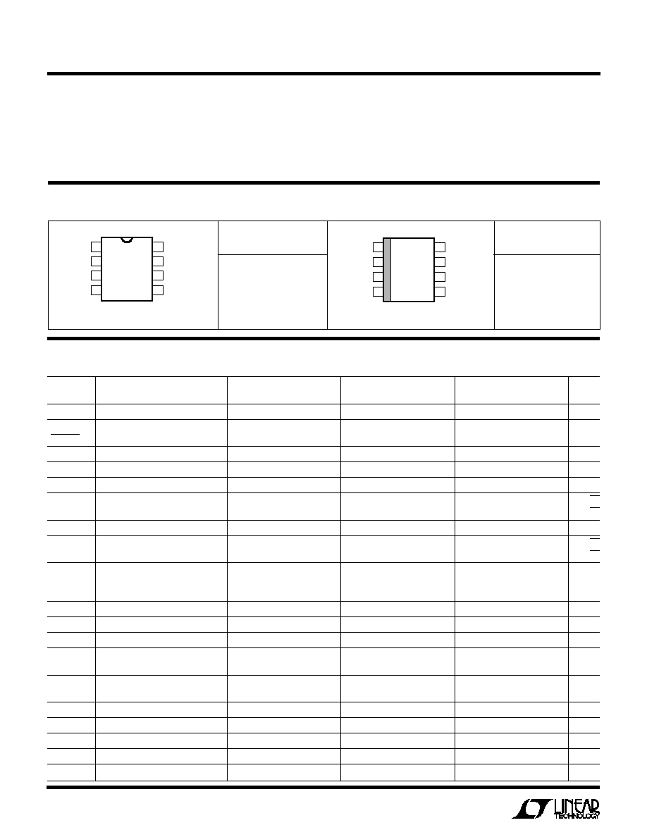
+
9V
OUT = 1.1V TO 8.0V
AS 1.8k
R2
135k
LT1097∑TA01
4
2
3
7
6
R1
20k
R2
1.018235V
2N3609
SATURATED
STANDARD
CELL #101
EPPLEY LABS
NEWPORT, R. I.
THE TYPICAL 40pA BIAS CURRENT OF THE LT1097
WILL DEGRADE THE STANDARD CELL BY ONLY
1ppm/YEAR. NOISE IS A FRACTION OF A ppm.
UNPROTECTED GATE MOSFET ISOLATES
STANDARD CELL ON POWER DOWN.
≠
+
LT1097
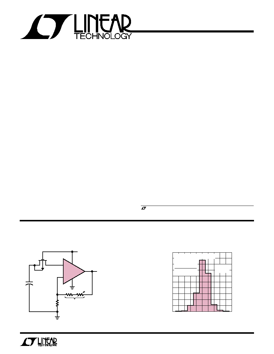
INPUT OFFSET VOLTAGE (
µ
V)
≠50 ≠40 ≠30 ≠20 ≠10 0
10 20 30 40 50
PERCENT OF UNITS
LT1097 ∑ G01
50
40
30
20
10
0
V
S
=
±
15V
T
A
= 25
∞
C
6,500 UNITS IN SO PACKAGE
6,680 UNITS IN
PLASTIC
DIP
13,180 UNITS
TESTED
Input Offset Voltage Distribution
Saturated Standard Cell Amplifier
2
LT1097
ABSOLUTE
M
AXI
M
U
M
RATINGS
W
W
W
U
PACKAGE/ORDER I
N
FOR
M
ATIO
N
W
U
U
ORDER
PART NUMBER
LT1097CN8
Supply Voltage ......................................................
±
20V
Differential Input Current (Note 1) ......................
±
10mA
Input Voltage .........................................................
±
20V
Output Short Circuit Duration .......................... Indefinite
1
2
3
4
8
7
6
5
TOP VIEW
V
OS
TRIM
≠IN
+IN
V
≠
V
OS
TRIM
V
+
OUT
OVER COMP
N8 PACKAGE
8-LEAD PLASTIC DIP
1
2
3
4
8
7
6
5
TOP VIEW
S8 PACKAGE
8-LEAD PLASTIC SO
V
OS
TRIM
≠IN
+IN
V
≠
V
OS
TRIM
V
+
OUT
OVER COMP
ORDER
PART NUMBER
LT1097S8
ELECTRICAL CHARACTERISTICS
V
S
=
±
15V, V
CM
= 0V, T
A
= 25
∞
C, unless otherwise noted.
LT1097CN8
LT1097S8
SYMBOL
PARAMETER
CONDITIONS
MIN
TYP
MAX
MIN
TYP
MAX
UNITS
V
OS
Input Offset Voltage
10
50
10
60
µ
V
V
OS
Long Term Input Offset
0.3
0.3
µ
V/Mo
TIME
Voltage Stability
I
OS
Input Offset Current
40
250
60
350
pA
I
B
Input Bias Current
±
40
±
250
±
50
±
350
pA
e
n
Input Noise Voltage
0.1Hz to 10Hz
0.5
0.5
µ
Vp-p
Input Noise Voltage Density
f
O
= 10Hz
16
16
nV/
Hz
f
O
= 1000Hz
14
14
nV/
Hz
i
n
Input Noise Current
0.1Hz to 10Hz
2.2
2.4
pAp-p
Input Noise Current Density
f
O
= 10Hz
0.03
0.035
pA/
Hz
f
O
= 1000Hz
0.008
0.008
pA/
Hz
Input Resistance
(Note 2)
Differential Mode
30
80
25
70
M
Common Mode
10
12
8∑10
11
Input Voltage Range
±
13.5
±
14.3
±
13.5
±
14.3
V
CMRR
Common Mode Rejection Ratio
V
CM
=
±
13.5V
115
130
115
130
dB
PSRR
Power Supply Rejection Ratio
V
S
=
±
1.2V to
±
20V
114
130
114
130
dB
A
VOL
Large Signal Voltage Gain
V
O
=
±
12V, R
L
= 10k
700
2500
700
2500
V/mV
V
O
=
±
10V, R
L
= 2k
250
1000
250
1000
V/mV
V
OUT
Output Voltage Swing
R
L
= 10k
±
13
±
13.8
±
13
±
13.8
V
R
L
= 2k
±
11.5
±
13
±
11.5
±
13
V
SR
Slew Rate
0.1
0.2
0.1
0.2
V/
µ
s
GBW
Gain Bandwidth Product
700
700
kHz
I
S
Supply Current
350
560
350
560
µ
A
Offset Adjustment Range
R
POT
= 10k, Wiper to V
+
±
600
±
600
µ
V
Minimum Supply Voltage
(Note 3)
±
1.2
--
±
1.2
--
V
Operating Temperature Range .................≠40
∞
C to 85
∞
C
Storage Temperature Range ..................≠65
∞
C to 150
∞
C
Lead Temperature (Soldering, 10 sec).................. 300
∞
C
3
LT1097
ELECTRICAL CHARACTERISTICS
V
S
=
±
15V, V
CM
= 0V, 0
∞
C
T
A
70
∞
C, unless otherwise noted.
LT1097CN8
LT1097S8
SYMBOL
PARAMETER
CONDITIONS
MIN
TYP
MAX
MIN
TYP
MAX
UNITS
V
OS
Input Offset Voltage
q
20
100
20
130
µ
V
Average Temperature Coefficient of (Note 4)
q
0.2
1
0.2
1.4
µ
V/
∞
C
Input Offset Voltage
I
OS
Input Offset Current
q
60
430
75
570
pA
Average Temperature Coefficient of (Note 4)
q
0.4
4
0.5
5
pA/
∞
C
Input Offset Current
I
B
Input Bias Current
q
±
60
±
430
±
75
±
570
pA
Average Temperature Coefficient of (Note 4)
q
0.4
4
0.5
5
pA/
∞
C
Input Bias Current
A
VOL
Large Signal Voltage Gain
V
OUT
=
±
12V, R
L
10k
q
450
2000
450
2000
V/mV
V
OUT
=
±
10V, R
L
2k
q
180
800
180
800
V/mV
CMRR
Common Mode Rejection Ratio
V
CM
=
±
13.5V
q
112
128
112
128
dB
PSRR
Power Supply Rejection Ratio
V
S
=
±
1.3V to
±
20V
q
111
128
111
128
dB
Input Voltage Range
q
±
13.5
±
14.2
±
13.5
±
14.2
V
V
OUT
Output Voltage Swing
R
L
= 10k
q
±
13
±
13.7
±
13
±
13.7
V
I
S
Supply Current
q
380
700
380
700
µ
A
ELECTRICAL CHARACTERISTICS
V
S
=
±
15V, V
CM
= 0V, ≠40
∞
C
T
A
85
∞
C, unless otherwise noted. (Note 5)
LT1097CN8
LT1097S8
SYMBOL
PARAMETER
CONDITIONS
MIN
TYP
MAX
MIN
TYP
MAX
UNITS
V
OS
Input Offset Voltage
q
25
130
30
170
µ
V
Average Temperature Coefficient of
q
0.3
1.2
0.3
1.6
µ
V/
∞
C
Input Offset Voltage
I
OS
Input Offset Current
q
70
600
85
750
pA
Average Temperature Coefficient of
q
0.5
5
0.6
6
pA/
∞
C
Input Offset Current
I
B
Input Bias Current
q
±
70
±
600
±
85
±
750
pA
Average Temperature Coefficient of
q
0.5
5
0.6
6
pA/
∞
C
Input Bias Current
A
VOL
Large Signal Voltage Gain
V
OUT
=
±
12V, R
L
10k
q
300
1700
300
1700
V/mV
V
OUT
=
±
10V, R
L
2k
q
700
700
V/mV
CMRR
Common Mode Rejection Ratio
V
CM
=
±
13.5V
q
108
127
108
127
dB
PSRR
Power Supply Rejection Ratio
V
S
=
±
1.5V to
±
20V
q
108
127
108
127
dB
Input Voltage Range
q
±
13.5
±
14
±
13.5
±
14
V
V
OUT
Output Voltage Swing
R
L
= 10k
q
±
13
±
13.6
±
13
±
13.6
V
I
S
Supply Current
q
400
800
400
800
µ
A
The
q
denotes specifications which apply over the full operating
temperature range.
Note 1: Differential input voltages greater than 1V will cause excessive
current to flow through the input protection diodes unless limiting
resistance is used.
Note 2: This parameter is guaranteed by design and is not tested.
Note 3: Power supply rejection ratio is measured at the minimum supply
voltage.
Note 4: This parameter is not 100% tested.
Note 5: The LT1097 is designed, characterized and expected to meet these
extended temperature limits, but is not tested at ≠40
∞
C and 85
∞
C.
Guaranteed I grade parts are available; consult factory.
4
LT1097
TYPICAL PERFOR
M
A
N
CE CHARACTERISTICS
U
W
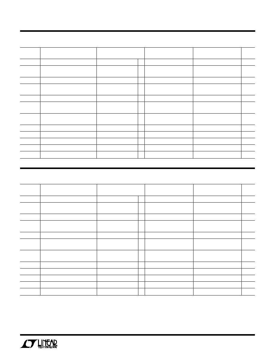
Distribution to Offset Voltage Drift
with Temperature
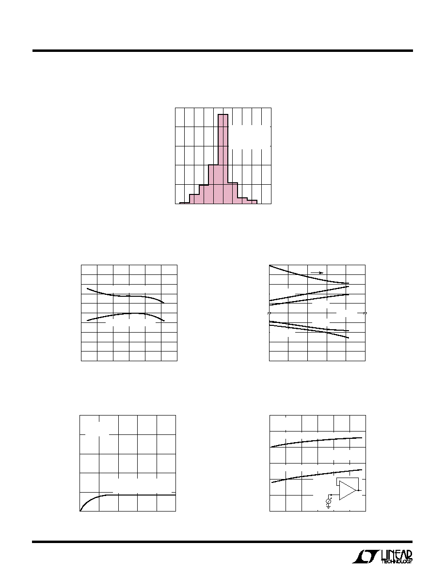
Input Bias Current vs Temperature
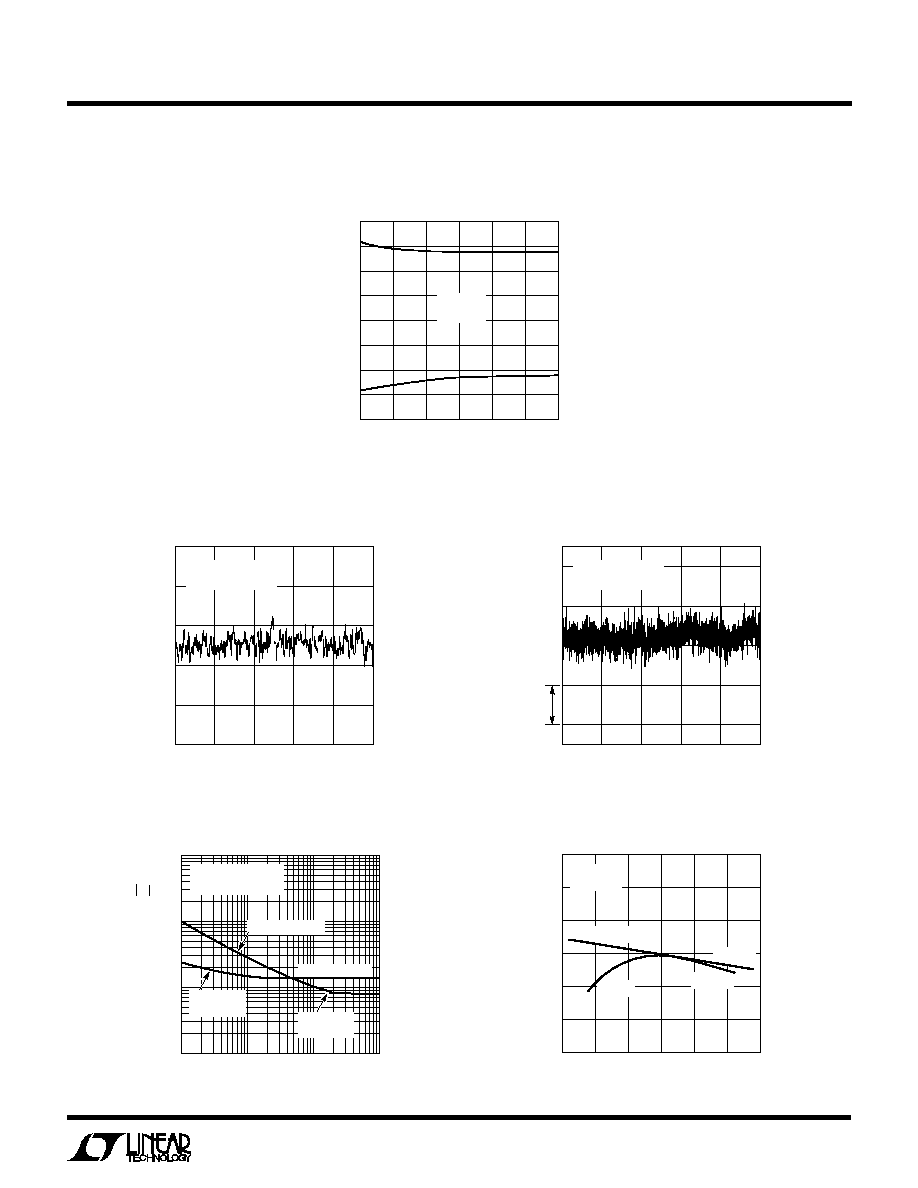
Minimum Supply Voltage,
Common Mode Range and
Voltage Swing at V
MIN
Warm-Up Drift
Input Bias Current Over Common
Mode Range
OFFSET VOLTAGE DRIFT WITH TEMPERATURE (
µ
V/
∞
C)
≠1.5 ≠1.2 ≠0.9 ≠0.6 ≠0.3 0
0.3 0.6 0.9 1.2 1.5
PERCENT OF UNITS
LT1097 ∑ G02
50
40
30
20
10
0
V
S
=
±
15V
240 UNITS TESTED
IN N8 PACKAGES
FROM SIX RUNS
TIME AFTER POWER ON (MINUTES)
0
1
2
3
4
5
CHANGE IN OFFSET VOLTAGE (
µ
V)
1097 ∑ G05
5
4
3
2
1
0
V
S
=
±
15V
T
A
= 25
∞
C
PLASTIC-IN-LINE PACKAGE
PLASTIC (N) OR SO (S)
TEMPERATURE (
∞
C)
≠50
0
50
≠25
25
75
100
INPUT BIAS CURRENT (pA)
1097 ∑ G03
200
100
0
≠100
≠200
≠300
UNDERCANCELLED UNIT
OVERCANCELLED UNIT
TEMPERATURE (
∞
C)
≠40
≠10
20
50
80
110
COMMON MODE RANGE OR OUTPUT SWING (V)
1097 ∑ G04
MINIMUM SUPPLY VOLTAGE, V
MIN
(V)
V
+
V
+
≠0.2
V
+
≠0.4
V
+
≠0.6
V
+
≠0.8
V
≠
+0.8
V
≠
+0.6
V
≠
+0.4
V
≠
+0.2
V
≠
±
1.4
±
1.2
±
1.0
±
0.8
CM RANGE
CM RANGE
SWING
R
L
= 10k
SWING
COMMON MODE INPUT VOLTAGE
≠15
≠5
5
≠10
0
10
15
INPUT BIAS CURRENT (pA)
1097 ∑ G06
120
80
40
0
≠40
≠80
≠120
V
S
=
±
15V
T
A
= 25
∞
C
R
IN CM
= 10
12
DEVICE WITH POSITIVE INPUT CURRENT
DEVICE WITH NEGATIVE INPUT CURRENT
V
CM
I
B
+
≠
5
LT1097
Output Short Circuit Current vs Time
TYPICAL PERFOR
M
A
N
CE CHARACTERISTICS
U
W
0.1Hz to 10Hz Noise
0.01Hz to 10Hz Noise
Noise Spectrum
TIME (SECONDS)
0
2
4
6
8
10
NOISE VOLTAGE (0.4
µ
V/DIV)
1097 ∑ G08
V
S
=
±
1.2V TO
±
20V
T
A
= 25
∞
C
TIME FROM OUTPUT SHORT (MINUTES)
0
1
2
3
SHORT CIRCUIT CURRENT (mA)
SINKING
SOURCING
1097 ∑ G07
20
15
10
5
0
≠5
≠10
≠15
≠20
V
S
=
±
15V
T
A
= 25
∞
C
TIME (SECONDS)
0
20
40
60
80
100
NOISE VOLTAGE (0.4
µ
V/DIV)
0.4
µ
V
1097 ∑ G09
V
S
=
±
1.2V TO
±
20V
T
A
= 25
∞
C
FREQUENCY (Hz)
1
1
10
100
1000
10
100
1000
1097 ∑ G10
VOLTAGE NOISE DENSITY (nV
Hz)
CURRENT NOISE DENSITY (fA
Hz)
T
A
= 25
∞
C
V
S
=
±
1.2V TO
±
20V
VOLTAGE NOISE
1/f CORNER
2.5Hz
1/f CORNER
140Hz
CURRENT NOISE
OUTPUT VOLTAGE (V)
≠15
≠5
5
≠10
0
10
15
CHANGE IN OFFSET VOLTAGE (
µ
V)
1097 ∑ G11
≠30
≠20
≠10
0
10
20
30
V
s
=
±
15 V
T
A
= 25
∞
C
R
L
= 10k
R
L
= 10k
R
L
= 2k
R
L
= 2k
Voltage Gain