1
LT1109A
Micropower
DC/DC Converter
Flash Memory VPP Generator
Adjustable and Fixed 5V, 12V
U
A
O
PPLICATI
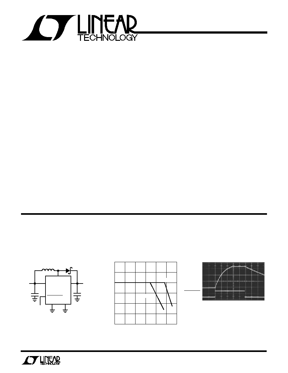
TYPICAL
Output Voltage
V
OUT
2V/DIV
SHUTDOWN
5V/DIV
500
µ
s/DIV
1109A TA03
12V
Output Current
OUTPUT CURRENT (mA)
0
OUTPUT VOLTAGE (V)
13.0
12.5
12.0
11.5
11.0
10.5
10.0
50
100
150
200
1109A TA02
250
300
V
IN
= 4.5V
V
IN
= 5V
S
FEATURE
s
Uses Off-the-Shelf Inductors
s
Low Cost
s
8-Pin DIP or SO Package
s
Fixed 5V or 12V Output or Adjustable Version
s
Only Four External Components Required
s
360
µ
A Standby Current
s
Logic-Controlled Shutdown
U
S
A
O
PPLICATI
s
Flash Memory VPP
Generators
s
5V to 12V Converters
s
3.3V to 12V Converters
s
Disk Drives
s
PC Plug-In Cards
s
Peripherals
s
Battery-Powered Equipment
The LT1109A is a simple step-up DC/DC converter. The 8-
pin DIP or SOIC devices require only four external compo-
nents to construct a complete DC/DC converter. Current
drain is just 360
µ
A at no load, making the device ideal for
cost-sensitive applications where standby current must
be kept to a minimum.
The LT1109A-12 can deliver 12V at over 150mA from a 5V
supply, enough power to program four flash memory
chips simultaneously. The LT1109A-5 can deliver 5V at up
to 110mA from a 2V input. The devices feature a shutdown
pin that turns off the oscillator when taken low. The gated-
oscillator design requires no frequency compensation
components. High frequency 120kHz operation permits
the use of small surface mount inductors and capacitors.
D
U
ESCRIPTIO
All Surface Mount
Flash Memory VPP
Generator
+
SENSE
V
IN
PGND
GND
LT1109ACS8-12
SHUTDOWN
SW
MBRS130T3
8
3
1
7
4
5
C2
47
µ
F
20V
V
OUT
12V
L1*
33
µ
H
COILTRONICS CTX33-2
SUMIDA CD54-330LC
1 = PROGRAM
0 = SHUTDOWN
+
+V
IN
5V
C1
22
µ
F
10V
1109A TA01
**
*
**
2
LT1109A
A
U
G
W
A
W
U
W
A
R
BSOLUTE
XI
TI
S
(Voltages Referred to GND Pin)
Supply Voltage (V
IN
) ................................ 0.4V to 20V
SW Pin Voltage ........................................ 0.4V to 50V
Feedback Pin Voltage (LT1109A) ........................... 5.5V
Shutdown Pin Voltage ........................................... 5.5V
Switch Current .......................................................... 2A
Maximum Power Dissipation ............................ 300mW
Operating Temperature Range .................... 0
°
C to 70
°
C
Storage Temperature Range ................ 65
°
C to 150
°
C
Lead Temperature (Soldering, 10 sec) .................. 300
°
C
T
JMAX
= 90
°
C,
JA
= 150
°
C/ W
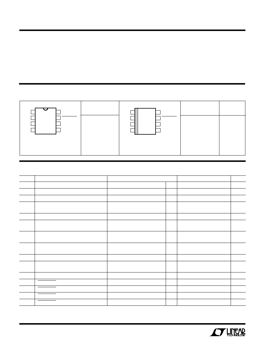
1
2
3
4
8
7
6
5
TOP VIEW
S8 PACKAGE
8-LEAD PLASTIC SO
*FIXED VERSIONS
V
IN
NC
SW
PGND
FB (SENSE)*
SHUTDOWN
NC
GND
LT1109ACS8
LT1109ACS8-5
LT1109ACS8-12
1109A
109A5
109A1
LT1109ACN8
LT1109ACN8-5
LT1109ACN8-12
W
U
U
PACKAGE/ORDER I FOR ATIO
ORDER PART
NUMBER
1
2
3
4
8
7
6
5
TOP VIEW
V
IN
NC
SW
PGND
N8 PACKAGE
8-LEAD PLASTIC DIP
*FIXED VERSIONS
FB (SENSE)*
SHUTDOWN
NC
GND
ORDER PART
NUMBER
S8 PART
MARKING
ELECTRICAL C
C
HARA TERISTICS
T
A
= 25
°
C, V
IN
= 3V, unless otherwise noted.
SYMBOL
PARAMETER
CONDITIONS
MIN
TYP
MAX
UNITS
I
Q
Quiescent Current
Switch Off
q
360
500
µ
A
V
IN
Input Voltage
q
2
9
V
Comparator Trip Point Voltage
LT1109A
q
1.20
1.25
1.30
V
V
OUT
Output Sense Voltage
LT1109A-5; 2V
V
IN
5V
q
4.75
5.00
5.25
V
LT1109A-12; 2V
V
IN
12V
q
11.52
12.00
12.55
V
Comparator Hysteresis
LT1109A
q
8
12.5
mV
Output Voltage Ripple
LT1109A-5
q
25
50
mV
LT1109A-12
q
60
120
mV
f
OSC
Oscillator Frequency
105
120
135
kHz
q
95
155
kHz
t
ON
Switch On Time
4.1
5.5
6.9
µ
s
q
3.8
7.4
µ
s
DC
Duty Cycle
Full Load
q
60
68
77
%
V
CESAT
Switch Saturation Voltage
V
IN
= 3V, I
SW
= 650mA
q
0.5
0.65
V
V
IN
= 5V, I
SW
= 1A
0.7
1.00
V
Switch Leakage Current
V
SW
= 12V
1
10
µ
A
V
IH
SHUTDOWN Pin High
q
2.0
V
V
IL
SHUTDOWN Pin Low
q
0.8
V
I
IH
SHUTDOWN Pin Input Current
V
SHUTDOWN
2.0V
q
10
µ
A
I
L
SHUTDOWN Pin Input Current
0V
V
SHUTDOWN
0.8V
q
20
µ
A
The
q
denotes specifications which apply over the full operating
temperature range.
T
JMAX
= 90
°
C,
JA
= 130
°
C/W

5
LT1109A
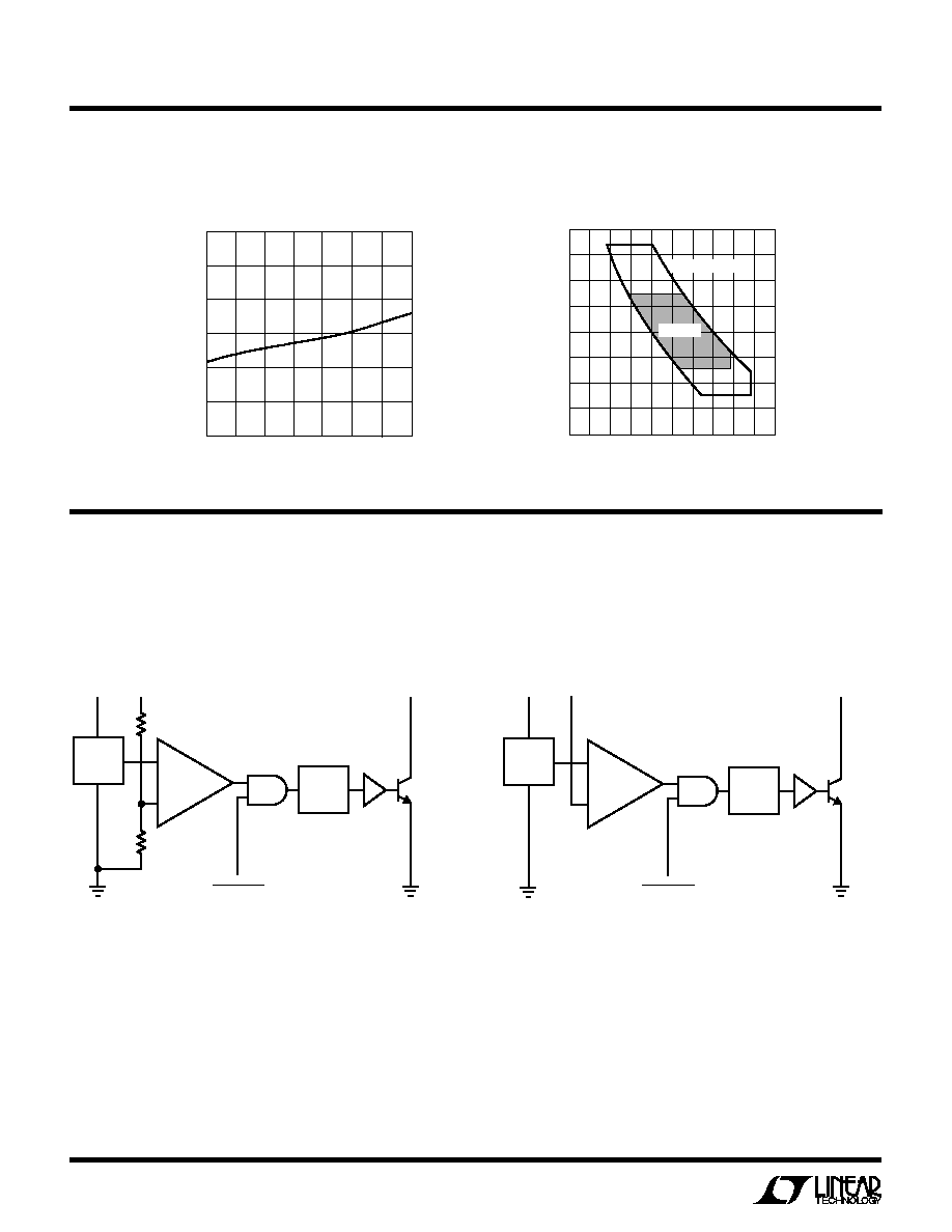
The LT1109A is a micropower step-up DC/DC converter.
It uses Burst Mode
TM
operation to achieve micropower
operation yet still deliver more than 2W of output power
from a 5V supply. Circuit operation can be best under-
stood by referring to the LT1109A block diagram. With
SHUTDOWN high, comparator A1 compares the feedback
(FB) pin voltage with the 1.25V reference signal. When FB
drops below 1.25V, A1 switches on the 120kHz oscillator.
The driver amplifier boosts the signal level to drive the
output NPN power switch. When the FB voltage is sufficient
to trip A1, the oscillator is turned off. A low signal on the
shutdown pin gates off the oscillator, overriding A1. With
SHUTDOWN low, quiescent current remains at 360
µ
A.
Burst Mode
TM
is a trademark of Linear Technology Corporation
OPERATIO
U
U
S
A
O
PPLICATI
W
U
U
I FOR ATIO
Inductor Selection
A DC/DC converter operates by storing energy as mag-
netic flux in an inductor core, and then switching this
energy into the load. To operate as an efficient energy
transfer element, the inductor must fulfill three require-
ments: inductance value, saturation current and DC resis-
tance. A fourth requirement is physical size. The inductors
recommended with the LT1109A circuits are small, sur-
face-mountable and are designed for switch-mode appli-
cations. Avoid using RF chokes or air core units since they
have very low peak current ratings. The LT1109A works
best in situations where the input voltage does not vary
much since the device has no internal switch current limit
function. For situations where the input voltage varies,
such as battery inputs, the LT1107 or LT1111 is suggested
instead.
Capacitor Selection
The output capacitor should be chosen on the basis of its
equivalent series resistance (ESR) and capacitance value.
Low ESR tantalum surface-mountable capacitors such as
those made by AVX are well-suited for DC/DC converter
applications. Inexpensive aluminum electrolytics may have
excessive ESR, resulting in high output ripple. These
should be avoided.
Diode Selection
Speed, forward drop, and leakage current are the three
main considerations in selecting a diode for LT1109A
converters. General purpose rectifiers such as the 1N4001
are
unsuitable for use in any switching regulator applica-
tion. Although they are rated at 1A, the switching time of
a 1N4001 is in the 10
µ
s to 50
µ
s range. At best, efficiency
will be severely compromised if this diode is used; at
worst, the circuit may not work at all. The 1N5818 is an
ideal choice for LT1109A circuits. Surface-mountable
versions, such as the MBRS130T3, are available as well.
Table 1. Inductor Manufacturers
MANUFACTURER
PART NUMBERS
Coiltronics International
Surface Mount
984 S.W. 13th Court
OCTA-PAC
TM
Series
Pompano Beach, FL 33069
305-781-8900
Sumida Electric Co., Ltd.
CD54
637 E. Golf Road, Suite 209
CD105
Arlington Heights, IL 60005
Surface Mount
708-956-0666
Table 2. Capacitor Manufacturers
MANUFACTURER
PART NUMBERS
AVX
TPS Series
Myrtle Beach, SC 29578
803-946-0690
Philips Components
49MC Series
2001 W. Blue Heron Blvd.
P.O. Box 10330
Riviera Beach, FL 33404
407-881-3200
Sanyo Video Components
OS-CON Series
1201 Sanyo Avenue
San Diego, CA 92073
619-661-6322
OCTA-PAC
TM
is a trademark of Coiltronics International