 | ÐлекÑÑоннÑй компоненÑ: LT1813I | СкаÑаÑÑ:  PDF PDF  ZIP ZIP |
1813/14f layout
1
LT1813/LT1814
FEATURES
APPLICATIO S
U
DESCRIPTIO
U
TYPICAL APPLICATIO
U
Dual/Quad 3mA, 100MHz,
750V/
µ
s Operational Amplifiers
The LT
®
1813/LT1814 are dual and quad, low power, high
speed, very high slew rate operational amplifiers with
excellent DC performance. The LT1813/LT1814 feature
reduced supply current, lower input offset voltage, lower
input bias current and higher DC gain than other devices
with comparable bandwidth. The circuit topology is a
voltage feedback amplifier with the slewing characteris-
tics of a current feedback amplifier.
The output drives a 100
load to
±
3.5V with
±
5V supplies.
On a single 5V supply, the output swings from 1.1V to 3.9V
with a 100
load connected to 2.5V. The amplifiers are
stable with a 1000pF capacitive load making them useful
in buffer and cable driver applications.
The LT1813/LT1814 are manufactured on Linear
Technology's advanced low voltage complementary bipo-
lar process. The LT1813 dual op amp is available in the
8-pin MSOP and SO packages. The quad LT1814 is
available in the 14-pin SO and 16-pin SSOP package. A
single version, the LT1812, is also available (see separate
data sheet).
s
100MHz Gain Bandwidth Product
s
750V/
µ
s Slew Rate
s
3.6mA Maximum Supply Current per Amplifier
s
8nV/
Hz Input Noise Voltage
s
Unity-Gain Stable
s
1.5mV Maximum Input Offset Voltage
s
4
µ
A Maximum Input Bias Current
s
400nA Maximum Input Offset Current
s
40mA Minimum Output Current, V
OUT
=
±
3V
s
±
3.5V Minimum Input CMR, V
S
=
±
5V
s
30ns Settling Time to 0.1%, 5V Step
s
Specified at
±
5V, Single 5V Supplies
s
Operating Temperature Range: 40
°
C to 85
°
C
s
Active Filters
s
Wideband Amplifiers
s
Buffers
s
Video Amplification
s
Communication Receivers
s
Cable Drivers
s
Data Acquisition Systems
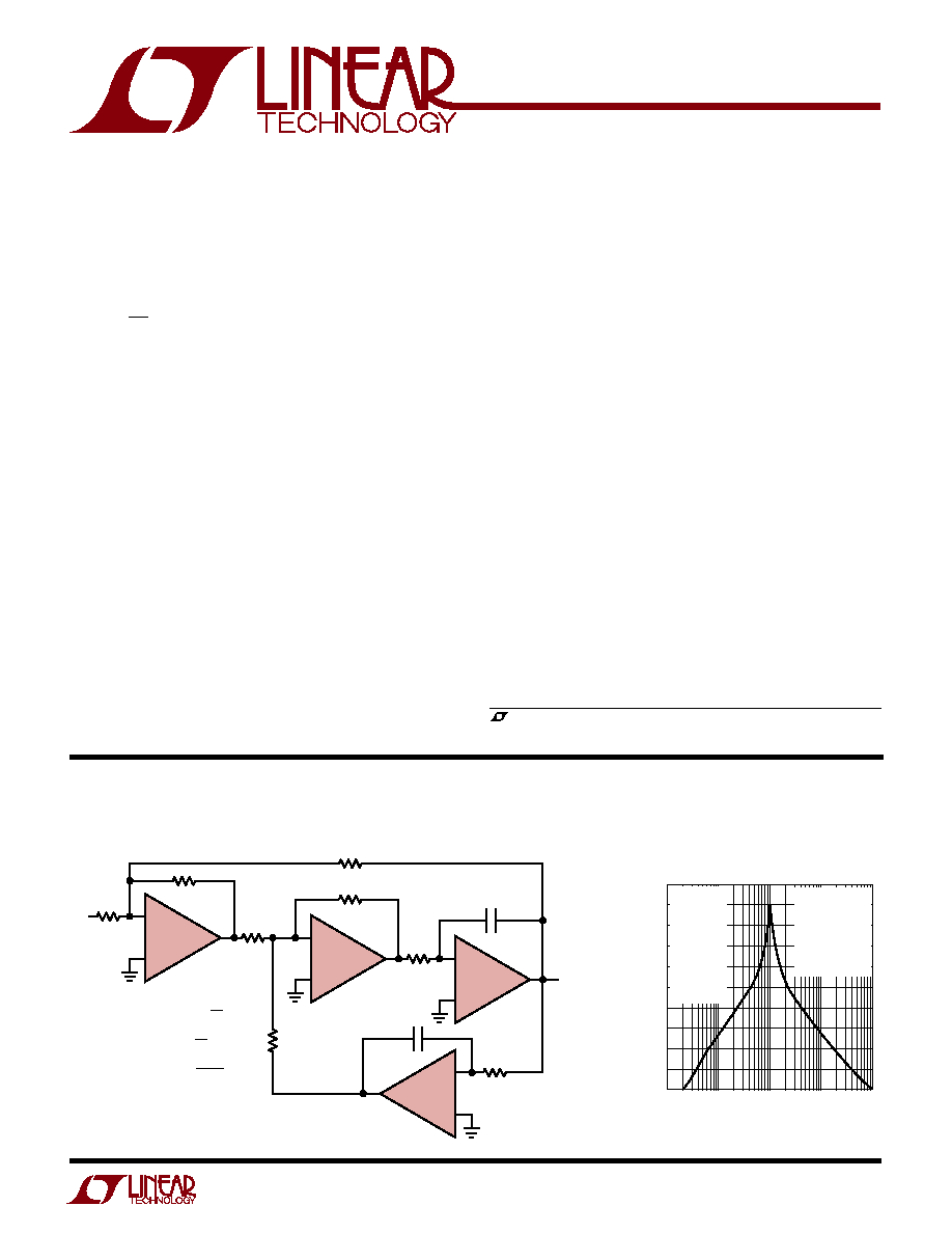
Bandpass Filter with Independently Settable Gain, Q and f
C
Filter Frequency Response
, LTC and LT are registered trademarks of Linear Technology Corporation.
+
1/4 LT1814
R
G
R
Q
R
R1
R
G
R
C
C
R1
R
F
R
F
R
V
IN
GAIN =
+
1/4 LT1814
+
+
1/4 LT1814
BANDPASS
OUT
1/4 LT1814
1814 TA01
R1
R
Q
Q =
1
2
R
F
C
f
C
=
FREQUENCY (Hz)
OUTPUT MAGNITUDE (6dB/DIV)
0
1k
100k
1M
10M
1814 TA02
10k
R = 499
R1 = 499
R
F
= 475
R
Q
= 49.9
R
G
= 499
C = 3.3nF
f
C
= 100kHz
Q = 10
GAIN = 1
V
S
=
±
5V
V
IN
= 5V
P-P
DISTORTION:
2nd < 76dB
3rd < 90dB
ACROSS FREQ
RANGE
2
LT1813/LT1814
Total Supply Voltage (V
+
to V
)
LT1813/LT1814 ................................................ 12.6V
LT1813HV ........................................................ 13.5V
Differential Input Voltage (Transient Only, Note 2) ..
±
6V
Input Voltage ............................................................
±
V
S
Output Short-Circuit Duration (Note 3) ........... Indefinite
ABSOLUTE AXI U RATI GS
W
W
W
U
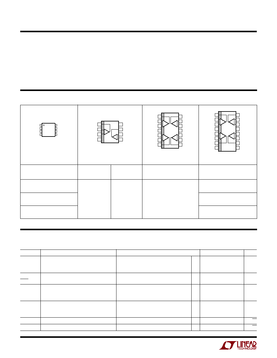
PACKAGE/ORDER I FOR ATIO
U
U
W
T
JMAX
= 150
°
C,
JA
= 250
°
C/W
Consult LTC marketing for parts specified with wider operating temperature ranges. *See Note 9.
Operating Temperature Range ................ 40
°
C to 85
°
C
Specified Temperature Range (Note 8) .. 40
°
C to 85
°
C
Maximum Junction Temperature ......................... 150
°
C
Storage Temperature Range ................ 65
°
C to 150
°
C
Lead Temperature (Soldering, 10 sec)................. 300
°
C
(Note 1)
ORDER PART
NUMBER
LT1814CS
LT1814IS
1
2
3
4
OUTA
IN A
+IN A
V
8
7
6
5
V
+
OUT B
IN B
+IN B
TOP VIEW
MS8 PACKAGE
8-LEAD PLASTIC MSOP
T
JMAX
= 150
°
C,
JA
= 110
°
C/W
TOP VIEW
V
+
OUT B
IN B
+IN B
OUT A
IN A
+IN A
V
S8 PACKAGE
8-LEAD PLASTIC SO
1
2
3
4
8
7
6
5
A
B
TOP VIEW
S PACKAGE
14-LEAD PLASTIC SO
1
2
3
4
5
6
7
14
13
12
11
10
9
8
OUT A
IN A
+IN A
V
+
+IN B
IN B
OUT B
OUT D
IN D
+IN D
V
+IN C
IN C
OUT C
+
+
+
+
A
B
D
C
LT1813DS8*
LT1813CS8
LT1813IS8
LT1813HVDS8*
LT1813HVCS8
LT1813HVIS8
ORDER PART
NUMBER
T
JMAX
= 150
°
C,
JA
= 150
°
C/W
LT1813DMS8*
MS8 PART
MARKING
LTGZ
ORDER PART
NUMBER
S8 PART
MARKING
1813D
1813
1813I
813HVD
1813HV
813HVI
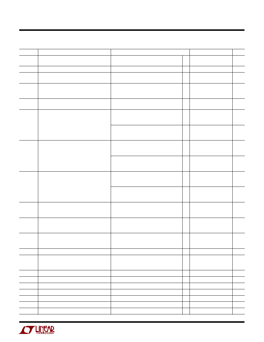
ELECTRICAL CHARACTERISTICS
The
q
denotes the specifications which apply over the full operating
temperature range, otherwise specifications are at T
A
= 25
°
C. V
S
=
±
5V, V
CM
= 0V, unless otherwise noted. (Note 8)
SYMBOL
PARAMETER
CONDITIONS
MIN
TYP
MAX
UNITS
V
OS
Input Offset Voltage
(Note 4)
0.5
1.5
mV
T
A
= 0
°
C to 70
°
C
q
2
mV
T
A
= 40
°
C to 85
°
C
q
3
mV
V
OS
Input Offset Voltage Drift
T
A
= 0
°
C to 70
°
C (Note 7)
q
10
15
µ
V/
°
C
T
T
A
= 40
°
C to 85
°
C (Note 7)
q
10
30
µ
V/
°
C
I
OS
Input Offset Current
50
400
nA
T
A
= 0
°
C to 70
°
C
q
500
nA
T
A
= 40
°
C to 85
°
C
q
600
nA
I
B
Input Bias Current
0.9
±
4
µ
A
T
A
= 0
°
C to 70
°
C
q
±
5
µ
A
T
A
= 40
°
C to 85
°
C
q
±
6
µ
A
e
n
Input Noise Voltage Density
f = 10kHz
8
nV/
Hz
i
n
Input Noise Current Density
f = 10kHz
1
pA/
Hz
TOP VIEW
GN PACKAGE
16-LEAD PLASTIC SSOP
1
2
3
4
5
6
7
8
16
15
14
13
12
11
10
9
OUT A
IN A
+IN A
V
+
+IN B
IN B
OUT B
NC
OUT D
IN D
+IN D
V
+IN C
IN C
OUT C
NC
+
+
+
+
A
B
D
C
T
JMAX
= 150
°
C,
JA
= 135
°
C/W
ORDER PART
NUMBER
GN PART
MARKING
LT1814CGN
LT1814IGN
1814
1814I
3
LT1813/LT1814
ELECTRICAL CHARACTERISTICS
The
q
denotes the specifications which apply over the full operating
temperature range, otherwise specifications are at T
A
= 25
°
C. V
S
=
±
5V, V
CM
= 0V, unless otherwise noted. (Note 8)
SYMBOL
PARAMETER
CONDITIONS
MIN
TYP
MAX
UNITS
R
IN
Input Resistance
V
CM
= 3.5V
3
10
M
Differential
1.5
M
C
IN
Input Capacitance
2
pF
V
CM
Input Voltage Range
Guaranteed by CMRR
±
3.5
±
4.2
V
T
A
= 40
°
C to 85
°
C
q
±
3.5
V
CMRR
Common Mode Rejection Ratio
V
CM
=
±
3.5V
75
85
dB
T
A
= 0
°
C to 70
°
C
q
73
dB
T
A
= 40
°
C to 85
°
C
q
72
dB
Minimum Supply Voltage
Guaranteed by PSRR
±
1.25
±
2
V
T
A
= 40
°
C to 85
°
C
q
±
2
V
PSRR
Power Supply Rejection Ratio
V
S
=
±
2V to
±
5.5V
78
97
dB
T
A
= 0
°
C to 70
°
C
q
76
dB
T
A
= 40
°
C to 85
°
C
q
75
dB
V
S
=
±
2V to
±
6.5V (LT1813HV)
75
97
dB
T
A
= 0
°
C to 70
°
C
q
73
dB
T
A
= 40
°
C to 85
°
C
q
72
dB
A
VOL
Large-Signal Voltage Gain
V
OUT
=
±
3V, R
L
= 500
1.5
3
V/mV
T
A
= 0
°
C to 70
°
C
q
1.0
V/mV
T
A
= 40
°
C to 85
°
C
q
0.8
V/mV
V
OUT
=
±
3V, R
L
= 100
1.0
2.5
V/mV
T
A
= 0
°
C to 70
°
C
q
0.7
V/mV
T
A
= 40
°
C to 85
°
C
q
0.6
V/mV
V
OUT
Maximum Output Swing
R
L
= 500
, 30mV Overdrive
±
3.8
±
4
V
(Positive/Negative)
T
A
= 0
°
C to 70
°
C
q
±
3.7
V
T
A
= 40
°
C to 85
°
C
q
±
3.6
V
R
L
= 100
, 30mV Overdrive
±
3.35
±
3.5
V
T
A
= 0
°
C to 70
°
C
q
±
3.25
V
T
A
= 40
°
C to 85
°
C
q
±
3.15
V
I
OUT
Maximum Output Current
V
OUT
=
±
3V, 30mV Overdrive
±
40
±
60
mA
T
A
= 0
°
C to 70
°
C
q
±
35
mA
T
A
= 40
°
C to 85
°
C
q
±
30
mA
I
SC
Output Short-Circuit Current
V
OUT
= 0V, 1V Overdrive (Note 3)
±
75
±
100
mA
T
A
= 0
°
C to 70
°
C
q
±
60
mA
T
A
= 40
°
C to 85
°
C
q
±
55
mA
SR
Slew Rate
A
V
= 1 (Note 5)
500
750
V/
µ
s
T
A
= 0
°
C to 70
°
C
q
400
V/
µ
s
T
A
= 40
°
C to 85
°
C
q
350
V/
µ
s
FPBW
Full Power Bandwidth
6V
P-P
(Note 6)
40
MHz
GBW
Gain Bandwidth Product
f = 200kHz, R
L
= 500
75
100
MHz
T
A
= 0
°
C to 70
°
C
q
65
MHz
T
A
= 40
°
C to 85
°
C
q
60
MHz
3dB BW
3dB Bandwidth
A
V
= 1, R
L
= 500
200
MHz
t
r
, t
f
Rise Time, Fall Time
A
V
= 1, 10% to 90%, 0.1V, R
L
= 100
2
ns
t
PD
Propagation Delay (Note 10)
A
V
= 1, 50% to 50%, 0.1V, R
L
= 100
2.8
ns
OS
Overshoot
A
V
= 1, 0.1V, R
L
= 100
25
%
t
S
Settling Time
A
V
= 1, 0.1%, 5V
30
ns
THD
Total Harmonic Distortion
A
V
= 2, f = 1MHz, V
OUT
= 2V
P-P
, R
L
= 500
76
dB
dG
Differential Gain
A
V
= 2, V
OUT
= 2V
P-P
, R
L
= 150
0.12
%

4
LT1813/LT1814
ELECTRICAL CHARACTERISTICS
The
q
denotes the specifications which apply over the full operating temperature range, otherwise specifications are at T
A
= 25
°
C.
V
S
= 5V, V
CM
= 2.5V, R
L
to 2.5V, unless otherwise noted. (Note 8)
The
q
denotes the specifications which apply over the full operating
temperature range, otherwise specifications are at T
A
= 25
°
C. V
S
=
±
5V, V
CM
= 0V, unless otherwise noted. (Note 8)
SYMBOL
PARAMETER
CONDITIONS
MIN
TYP
MAX
UNITS
dP
Differential Phase
A
V
= 2, V
OUT
= 2V
P-P
, R
L
= 150
0.07
DEG
R
OUT
Output Resistance
A
V
= 1, f = 1MHz
0.4
Channel Separation
V
OUT
=
±
3V, R
L
= 100
82
100
dB
T
A
= 0
°
C to 70
°
C
q
81
dB
T
A
= 40
°
C to 85
°
C
q
80
dB
I
S
Supply Current
Per Amplifier
3
3.6
mA
T
A
= 0
°
C to 70
°
C
q
4.5
mA
T
A
= 40
°
C to 85
°
C
q
5.0
mA
Per Amplifier,V
S
=
±
6.5V, (LT1813HV only)
4.0
mA
T
A
= 0
°
C to 70
°
C
q
5.0
mA
T
A
= 40
°
C to 85
°
C
q
5.5
mA
V
OS
Input Offset Voltage
(Note 4)
0.7
2.0
mV
T
A
= 0
°
C to 70
°
C
q
2.5
mV
T
A
= 40
°
C to 85
°
C
q
3.5
mV
V
OS
Input Offset Voltage Drift
T
A
= 0
°
C to 70
°
C (Note 7)
q
10
15
µ
V/
°
C
T
T
A
= 40
°
C to 85
°
C (Note 7)
q
10
30
µ
V/
°
C
I
OS
Input Offset Current
50
400
nA
T
A
= 0
°
C to 70
°
C
q
500
nA
T
A
= 40
°
C to 85
°
C
q
600
nA
I
B
Input Bias Current
1
±
4
µ
A
T
A
= 0
°
C to 70
°
C
q
±
5
µ
A
T
A
= 40
°
C to 85
°
C
q
±
6
µ
A
e
n
Input Noise Voltage Density
f = 10kHz
8
nV/
Hz
i
n
Input Noise Current Density
f = 10kHz
1
pA/
Hz
R
IN
Input Resistance
V
CM
= 3.5V
3
10
M
Differential
1.5
M
C
IN
Input Capacitance
2
pF
V
CM
Input Voltage Range
Guaranteed by CMRR
3.5
4.2
V
(Positive)
T
A
= 40
°
C to 85
°
C
q
3.5
V
Input Voltage Range
Guaranteed by CMRR
0.8
1.5
V
(Negative)
T
A
= 40
°
C to 85
°
C
q
1.5
V
CMRR
Common Mode Rejection Ratio
V
CM
= 1.5V to 3.5V
73
82
dB
T
A
= 0
°
C to 70
°
C
q
71
dB
T
A
= 40
°
C to 85
°
C
q
70
dB
Minimum Supply Voltage
Guaranteed by PSRR
2.5
4
V
T
A
= 40
°
C to 85
°
C
q
4
V
A
VOL
Large-Signal Voltage Gain
V
OUT
= 1.5V to 3.5V, R
L
= 500
1.0
2
V/mV
T
A
= 0
°
C to 70
°
C
q
0.7
V/mV
T
A
= 40
°
C to 85
°
C
q
0.6
V/mV
V
OUT
= 1.5V to 3.5V, R
L
= 100
0.7
1.5
V/mV
T
A
= 0
°
C to 70
°
C
q
0.5
V/mV
T
A
= 40
°
C to 85
°
C
q
0.4
V/mV
5
LT1813/LT1814
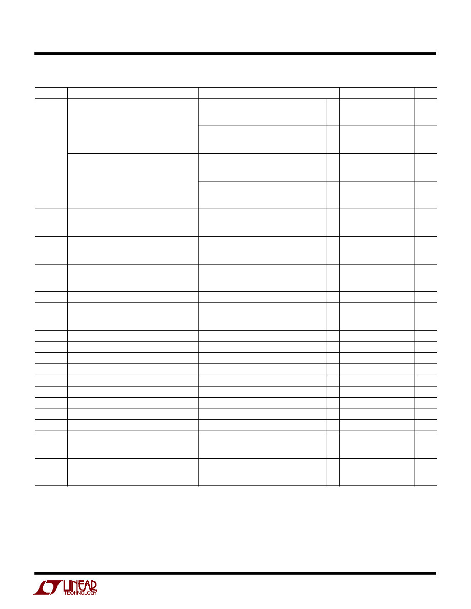
ELECTRICAL CHARACTERISTICS
The
q
denotes the specifications which apply over the full operating
temperature range, otherwise specifications are at T
A
= 25
°
C. V
S
= 5V, V
CM
= 2.5V, R
L
to 2.5V, unless otherwise noted. (Note 8)
SYMBOL
PARAMETER
CONDITIONS
MIN
TYP
MAX
UNITS
V
OUT
Maximum Output Swing
R
L
= 500
, 30mV Overdrive
3.9
4.1
V
(Positive)
T
A
= 0
°
C to 70
°
C
q
3.8
V
T
A
= 40
°
C to 85
°
C
q
3.7
V
R
L
= 100
, 30mV Overdrive
3.7
3.9
V
T
A
= 0
°
C to 70
°
C
q
3.6
V
T
A
= 40
°
C to 85
°
C
q
3.5
V
Maximum Output Swing
R
L
= 500
, 30mV Overdrive
0.9
1.1
V
(Negative)
T
A
= 0
°
C to 70
°
C
q
1.2
V
T
A
= 40
°
C to 85
°
C
q
1.3
V
R
L
= 100
, 30mV Overdrive
1.1
1.3
V
T
A
= 0
°
C to 70
°
C
q
1.4
V
T
A
= 40
°
C to 85
°
C
q
1.5
V
I
OUT
Maximum Output Current
V
OUT
= 1.5V or 3.5V, 30mV Overdrive
±
25
±
35
mA
T
A
= 0
°
C to 70
°
C
q
±
20
mA
T
A
= 40
°
C to 85
°
C
q
±
17
mA
I
SC
Output Short-Circuit Current
V
OUT
= 2.5V, 1V Overdrive (Note 3)
±
55
±
75
mA
T
A
= 0
°
C to 70
°
C
q
±
45
mA
T
A
= 40
°
C to 85
°
C
q
±
40
mA
SR
Slew Rate
A
V
= 1 (Note 5)
200
350
V/
µ
s
T
A
= 0
°
C to 70
°
C
q
150
V/
µ
s
T
A
= 40
°
C to 85
°
C
q
125
V/
µ
s
FPBW
Full Power Bandwidth
2V
P-P
(Note 6)
55
MHz
GBW
Gain Bandwidth Product
f = 200kHz, R
L
= 500
65
94
MHz
T
A
= 0
°
C to 70
°
C
q
55
MHz
T
A
= 40
°
C to 85
°
C
q
50
MHz
3dB BW
3dB Bandwidth
A
V
= 1, R
L
= 500
180
MHz
t
r
, t
f
Rise Time, Fall Time
A
V
= 1, 10% to 90%, 0.1V, R
L
= 100
2.1
ns
t
PD
Propagation Delay (Note 10)
A
V
= 1, 50% to 50%, 0.1V, R
L
= 100
3
ns
OS
Overshoot
A
V
= 1, 0.1V, R
L
= 100
25
%
t
S
Settling Time
A
V
= 1, 0.1%, 2V
30
ns
THD
Total Harmonic Distortion
A
V
= 2, f = 1MHz, V
OUT
= 2V
P-P
, R
L
= 500
75
dB
dG
Differential Gain
A
V
= 2, V
OUT
= 2V
P-P
, R
L
= 150
0.22
%
dP
Differential Phase
A
V
= 2, V
OUT
= 2V
P-P
, R
L
= 150
0.21
DEG
R
OUT
Output Resistance
A
V
= 1, f = 1MHz
0.45
Channel Separation
V
OUT
= 1.5V to 3.5V, R
L
= 100
81
100
dB
T
A
= 0
°
C to 70
°
C
q
80
dB
T
A
= 40
°
C to 85
°
C
q
79
dB
I
S
Supply Current
Per Amplifier
2.9
4.0
mA
T
A
= 0
°
C to 70
°
C
q
5.0
mA
T
A
= 40
°
C to 85
°
C
q
5.5
mA