 | ÐлекÑÑоннÑй компоненÑ: LT1993-10 | СкаÑаÑÑ:  PDF PDF  ZIP ZIP |
199310f.indd

LT1993-10
1
199310f
4-Tone WCDMA Waveform,
LT1993-10 Driving LTC2255
14-Bit ADC at 92.16Msps
700MHz Low Distortion, Low
Noise Differential Amplifi er/
ADC Driver (A
V
= 10V/V)
The LT
®
1993-10 is a low distortion, low noise Differential
Amplifi er/ADC driver for use in applications from DC to
700MHz. The LT1993-10 has been designed for ease of
use, with minimal support circuitry required. Exception-
ally low input-referred noise and low distortion products
(with either single-ended or differential inputs) make the
LT1993-10 an excellent solution for driving high speed
12-bit and 14-bit ADCs. In addition to the normal unfi ltered
outputs (+OUT and OUT), the LT1993-10 has a built-in
175MHz differential lowpass fi lter and an additional pair
of fi ltered outputs (+OUTFILTERED, OUTFILTERED) to
reduce external fi ltering components when driving high
speed ADCs. The output common mode voltage is easily set
via the V
OCM
pin, eliminating either an output transformer
or AC-coupling capacitors in many applications.
The LT1993-10 is designed to meet the demanding require-
ments of communications transceiver applications. It can
be used as a differential ADC driver, a general-purpose
differential gain block, or in any other application requir-
ing differential drive. The LT1993-10 can be used in data
acquisition systems required to function at frequencies
down to DC.
The LT1993-10 operates on a 5V supply and consumes
100mA. It comes in a compact 16-lead 3 × 3 QFN package
and operates over a 40°C to 85°C temperature range.
Differential ADC Driver for:
Imaging
Communications
Differential Driver/Receiver
Single Ended to Differential Conversion
Differential to Single Ended Conversion
Level Shifting
IF Sampling Receivers
SAW Filter Interfacing/Buffering
700MHz 3dB Bandwidth
Fixed Gain of 10V/V (20dB)
Low Distortion:
40dBm OIP3, 70dBc HD3 (70MHz 2V
P-P
)
50.5dBm OIP3, 91dBc (10MHz 2V
P-P
)
Low Noise: 12.7dB NF, e
n
= 1.9nV/Hz
Differential Inputs and Outputs
Additional Filtered Outputs
Adjustable Output Common Mode Voltage
DC- or AC-Coupled Operation
Minimal Support Circuitry Required
Small 0.8mm Tall 16-Lead 3 × 3 QFN Package
4-Channel WCDMA Receive Channel
APPLICATIO S
U
FEATURES
DESCRIPTIO
U
TYPICAL APPLICATIO
U
, LTC and LT are registered trademarks of Linear Technology Corporation.
All other trademarks are the property of their respective owners.
·
·
2.2V
20dB Gain
199310 TA01
MA/COM
ETC 1-1-13
1:1
Z-RATIO
LTC2255 125Msps
14-BIT ADC SAMPLING
AT 96.12Msps
70MHz
IF IN
52.3pF
82nH
LT1993-10
INA
INB
OUTFILTERED
OUT
+OUTFILTERED
+OUT
+INB
+INA
V
OCM
ENABLE
LTC2255
ADC
AIN
AIN+
FREQUENCY (MHz)
0
120
AMPLITUDE (dBFS)
100
80
60
40
0
5
10
15
25
199310 · TA02
35
20
30
40
45
20
110
90
70
50
30
10
32768 POINT FFT
TONE CENTER FREQUENCIES
AT 62.5MHz, 67.5MHz,
72.5MHz, 77.5MHz

LT1993-10
2
199310f
16 15 14 13
5
6
7
8
TOP VIEW
UD PACKAGE
16-LEAD (3mm
× 3mm) PLASTIC QFN
9
10
17
11
12
4
3
2
1
V
CCC
V
OCM
V
CCA
V
EEA
V
EEC
ENABLE
V
CCB
V
EEB
+INA
+INB
INA
INB
+OUT
+OUTFILTERED
OUTFILTERED
OUT
Total Supply Voltage (V
CCA
/V
CCB
/V
CCC
to
V
EEA
/V
EEB
/V
EEC
) ...................................................5.5V
Input Current (+INA, INA, +INB, INB,
V
OCM
, ENABLE) ................................................±10mA
Output Current (Continuous)
+OUT, OUT (DC) ..........................................±100mA
(AC)
..........................................±100mA
+OUTFILTERED,
OUTFILTERED
(DC)
.............±15mA
(AC)
.............±45mA
Output Short Circuit Duration (Note 2) ............ Indefi nite
Operating Temperature Range (Note 3) ... 40°C to 85°C
Specifi ed Temperature Range (Note 4) .... 40°C to 85°C
Storage Temperature Range ................... 65°C to 125°C
Junction Temperature ........................................... 125°C
Lead Temperature Range (Soldering 10 sec) ........ 300°C
ORDER PART NUMBER
UD PART MARKING*
Consult LTC Marketing for parts specifi ed with wider operating temperature ranges.
*The temperature grade is identifi ed by a label on the shipping container.
LBNT
LBNT
LT1993CUD-10
LT1993IUD-10
(Note 1)
The
denotes the specifi cations which apply over the full operating
temperature range, otherwise specifi cations are at T
A
= 25°C. V
CCA
= V
CCB
= V
CCC
= 5V, V
EEA
= V
EEB
= V
EEC
= 0V, ENABLE = 0.8V, +INA
shorted to +INB (+IN), INA shorted to INB (IN), V
OCM
= 2.2V, Input common mode voltage = 2.2V, no R
LOAD
unless otherwise noted.
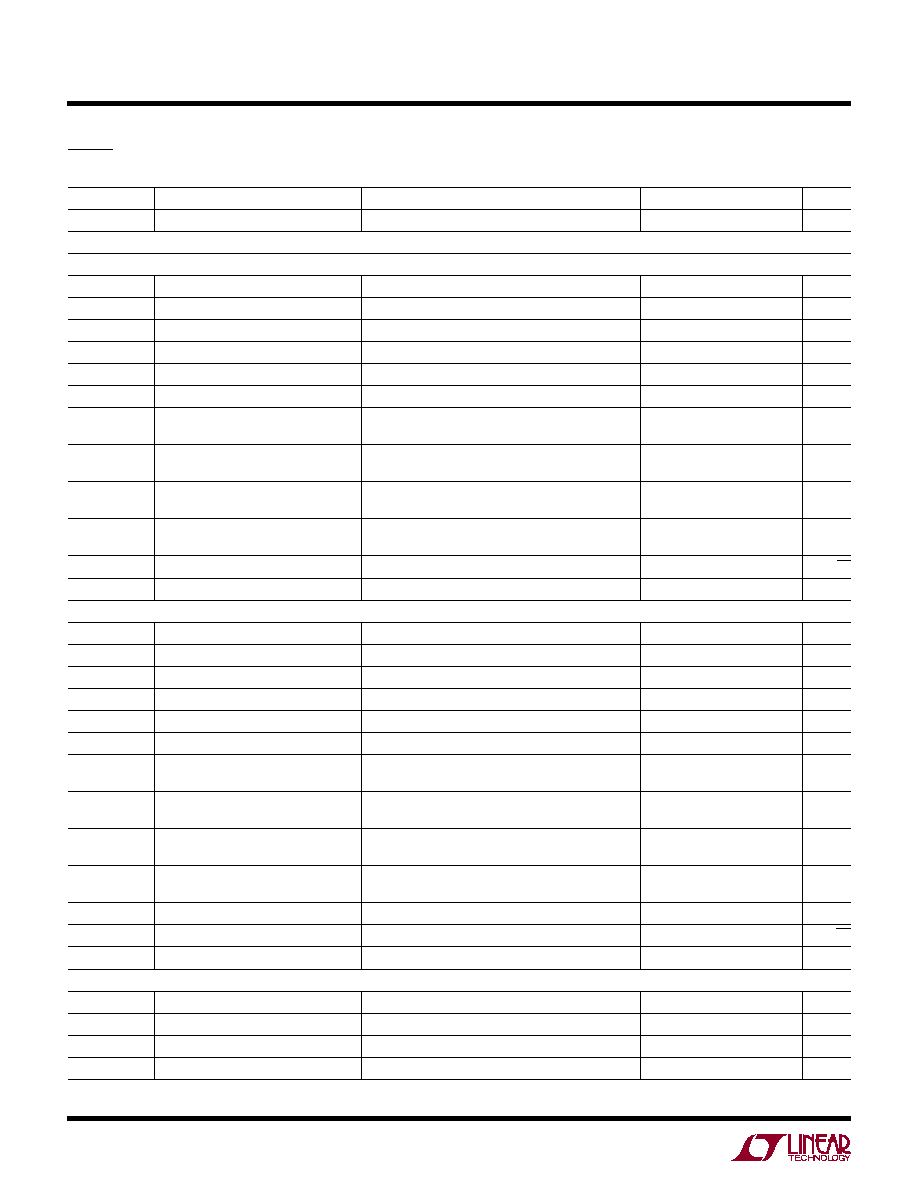
SYMBOL
PARAMETER
CONDITIONS
MIN
TYP
MAX
UNITS
Input/Output Characteristics (+INA, +INB, INA, INB, +OUT, OUT, +OUTFILTERED, OUTFILTERED)
GDIFF
Gain
Differential (+OUT, OUT), V
IN
= ±160mV Differential
18.9
19.7
20.9
dB
V
SWINGMIN
Single-Ended +OUT, OUT, +OUTFILTERED,
OUTFILTERED. V
IN
= ±600mV Differential
0.25
0.35
0.5
V
V
V
SWINGMAX
Single-Ended +OUT, OUT, +OUTFILTERED,
OUTFILTERED. V
IN
= ±600mV Differential
3.6
3.5
3.75
V
V
V
SWINGDIFF
Output Voltage Swing
Differential (+OUT, OUT), V
IN
= ±600mV Differential
6.5
6
7
V
P-P
V
P-P
I
OUT
Output Current Drive
±40
±45
mA
V
OS
Input Offset Voltage
6.5
10
1
6.5
10
mV
mV
TCV
OS
Input Offset Voltage Drift
T
MIN
to T
MAX
2.5
µV/°C
I
VRMIN
Input Voltage Range, MIN
Single-Ended
0.9
V
I
VRMAX
Input Voltage Range, MAX
Single-Ended
3.9
V
R
INDIFF
Input Resistance
77
100
122
C
INDIFF
Input Capacitance
1
pF
ABSOLUTE AXI U
RATI GS
W
W
W
U
PACKAGE/ORDER I FOR ATIO
U
U
W
DC ELECTRICAL CHARACTERISTICS
T
JMAX
= 125°C,
JA
= 68°C/W,
JC
= 4.2°C/W
EXPOSED PAD IS V
EE
(PIN 17)
MUST BE SOLDERED TO THE PCB
Order Options Tape and Reel: Add #TR
Lead Free: Add #PBF Lead Free Tape and Reel: Add #TRPBF
Lead Free Part Marking:
http://www.linear.com/leadfree/

LT1993-10
3
199310f
SYMBOL
PARAMETER
CONDITIONS
MIN
TYP
MAX
UNITS
Input/Output Characteristics
3dBBW
3dB Bandwidth
200mV
P-P
Differential (+OUT, OUT)
500
700
MHz
0.1dBBW
Bandwidth for 0.1dB Flatness
200mV
P-P
Differential (+OUT, OUT)
50
MHz
0.5dBBW
Bandwidth for 0.5dB Flatness
200mV
P-P
Differential (+OUT, OUT)
100
MHz
SR
Slew Rate
3.2V
P-P
Differential (+OUT, OUT)
1100
V/µs
t
s1%
1% Settling Time
1% Settling for a 1V
P-P
Differential Step
(+OUT, OUT)
4
ns
t
ON
Turn-On Time
40
ns
t
OFF
Turn-Off Time
250
ns
Common Mode Voltage Control (V
OCM
Pin)
3dBBW
CM
Common Mode Small-Signal 3dB
Bandwidth
0.1V
P-P
at V
OCM
, Measured Single-Ended at +OUT
and OUT
300
MHz
SYMBOL
PARAMETER
CONDITIONS
MIN
TYP
MAX
UNITS
CMRR
Common Mode Rejection Ratio
Input Common Mode 0.9V to 3.9V
45
70
dB
R
OUTDIFF
Output Resistance
0.3
C
OUTDIFF
Output Capacitance
0.8
pF
Common Mode Voltage Control (V
OCM
Pin)
GCM
Common Mode Gain
Differential (+OUT, OUT), V
OCM
= 1.2V to 3.6V
Differential (+OUT, OUT), V
OCM
= 1.4V to 3.4V
0.9
0.9
1
1.1
1.1
V/V
V/V
V
OCMMIN
Output Common Mode Voltage
Adjustment Range, MIN
Single-Ended
1.2
1.4
V
V
V
OCMMAX
Output Common Mode Voltage
Adjustment Range, MAX
Single-Ended
3.6
3.4
V
V
V
OSCM
Output Common Mode Offset
Voltage
Measured from V
OCM
to Average of +OUT and OUT
30
2
30
mV
I
BIASCM
V
OCM
Input Bias Current
5
15
µA
R
INCM
V
OCM
Input Resistance
0.8
3
M
C
INCM
V
OCM
Input Capacitance
1
pF
ENABLE Pin
V
IL
ENABLE Input Low Voltage
0.8
V
V
IH
ENABLE Input High Voltage
2
V
I
IL
ENABLE Input Low Current
ENABLE = 0.8V
0.5
µA
I
IH
ENABLE Input High Current
ENABLE = 2V
1
3
µA
Power Supply
V
S
Operating Range
4
5
5.5
V
I
S
Supply Current
ENABLE = 0.8V
88
100
112
mA
I
SDISABLED
Supply Current (Disabled)
ENABLE = 2V
250
500
µA
PSRR
Power Supply Rejection Ratio
4V to 5.5V
55
90
dB
The
denotes the specifi cations which apply over the full operating
temperature range, otherwise specifi cations are at T
A
= 25°C. V
CCA
= V
CCB
= V
CCC
= 5V, V
EEA
= V
EEB
= V
EEC
= 0V, ENABLE = 0.8V, +INA
shorted to +INB (+IN), INA shorted to INB (IN), V
OCM
= 2.2V, Input common mode voltage = 2.2V, no R
LOAD
unless otherwise noted.
T
A
= 25°C, V
CCA
= V
CCB
= V
CCC
= 5V, V
EEA
= V
EEB
= V
EEC
= 0V,
ENABLE = 0.8V, +INA shorted to +INB (+IN), INA shorted to INB (IN), V
OCM
= 2.2V, Input common mode voltage = 2.2V, no R
LOAD
unless otherwise noted.
DC ELECTRICAL CHARACTERISTICS
AC ELECTRICAL CHARACTERISTICS
LT1993-10
4
199310f
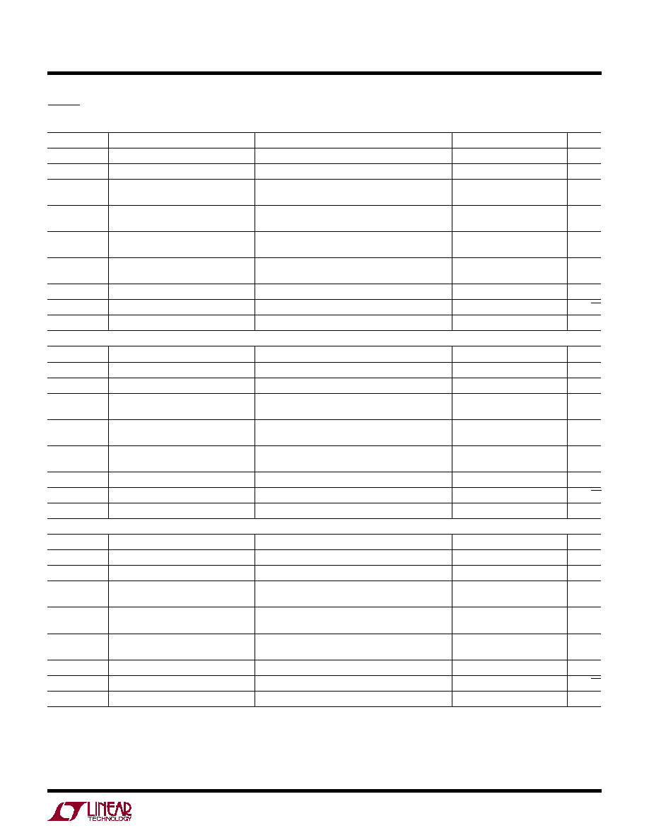
SYMBOL
PARAMETER
CONDITIONS
MIN
TYP
MAX
UNITS
SRCM
Common Mode Slew Rate
1.2V to 3.6V Step at V
OCM
500
V/µs
Noise/Harmonic Performance Input/output Characteristics
1kHz Signal
Second/Third Harmonic Distortion
2V
P-P
Differential (+OUTFILTERED, OUTFILTERED)
100
dBc
2V
P-P
Differential (+OUT, OUT)
100
dBc
2V
P-P
Differential (+OUT, OUT), R
L
= 100
100
dBc
3.2V
P-P
Differential (+OUTFILTERED, OUTFILTERED)
91
dBc
3.2V
P-P
Differential (+OUT, OUT)
91
dBc
3.2V
P-P
Differential (+OUT, OUT), R
L
= 100
91
dBc
Third-Order IMD
2V
P-P
Differential Composite (+OUTFILTERED,
OUTFILTERED), f1 = 0.95kHz, f2 = 1.05kHz
102
dBc
2V
P-P
Differential Composite (+OUT, OUT),
R
L
= 100, f1 = 0.95kHz, f2 = 1.05kHz
102
dBc
3.2V
P-P
Differential Composite (+OUTFILTERED,
OUTFILTERED), f1 = 0.95kHz, f2 = 1.05kHz
93
dBc
OIP3
1k
Output Third-Order Intercept
Differential (+OUTFILTERED, OUTFILTERED),
f1 = 0.95kHz, f2 = 1.05kHz
54
dBm
e
n1k
Input Referred Noise Voltage Density
1.7
nV/Hz
1dB Compression Point
22.7
dBm
10MHz Signal
Second/Third Harmonic Distortion
2V
P-P
Differential (+OUTFILTERED, OUTFILTERED)
91
dBc
2V
P-P
Differential (+OUT, OUT)
91
dBc
2V
P-P
Differential (+OUT, OUT), R
L
= 100
83
dBc
3.2V
P-P
Differential (+OUTFILTERED, OUTFILTERED)
82
dBc
3.2V
P-P
Differential (+OUT, OUT)
82
dBc
3.2V
P-P
Differential (+OUT, OUT), R
L
= 100
74
dBc
Third-Order IMD
2V
P-P
Differential Composite (+OUTFILTERED,
OUTFILTERED), f1 = 9.5MHz, f2 = 10.5MHz
95
dBc
2V
P-P
Differential Composite (+OUT, OUT),
R
L
= 100, f1 = 9.5MHz, f2 = 10.5MHz
94
dBc
3.2V
P-P
Differential Composite (+OUTFILTERED,
OUTFILTERED), f1 = 9.5MHz, f2 = 10.5MHz
85
dBc
OIP3
10M
Output Third-Order Intercept
Differential (+OUTFILTERED, OUTFILTERED),
f1 = 9.5MHz, f2 = 10.5MHz
50.5
dBm
NF
Noise Figure
Measured Using DC800A Demo Board
11.8
dBm
e
n10M
Input Referred Noise Voltage Density
1.7
nV/Hz
1dB Compression Point
22.6
dBm
50MHz Signal
Second/Third Harmonic Distortion
2V
P-P
Differential (+OUTFILTERED, OUTFILTERED)
77
dBc
2V
P-P
Differential (+OUT, OUT)
77
dBc
2V
P-P
Differential (+OUT, OUT), R
L
= 100
73
dBc
3.2V
P-P
Differential (+OUTFILTERED, OUTFILTERED)
68
dBc
T
A
= 25°C, V
CCA
= V
CCB
= V
CCC
= 5V, V
EEA
= V
EEB
= V
EEC
= 0V,
ENABLE = 0.8V, +INA shorted to +INB (+IN), INA shorted to INB (IN), V
OCM
= 2.2V, Input common mode voltage = 2.2V, no R
LOAD
unless otherwise noted.
AC ELECTRICAL CHARACTERISTICS
LT1993-10
5
199310f
Note 1: Absolute Maximum Ratings are those values beyond which the life of a
device may be impaired.
Note 2: As long as output current and junction temperature are kept below the
Absolute Maximum Ratings, no damage to the part will occur.
Note 3: The LT1993C-10 is guaranteed functional over the operating temperature
range of 40°C to 85°C.
Note 4: The LT1993C-10 is guaranteed to meet specifi ed performance from 0°C
to 70°C. It is designed, characterized and expected to meet specifi ed performance
from 40°C and 85°C but is not tested or QA sampled at these temperatures. The
LT1993I-10 is guaranteed to meet specifi ed performance from 40°C to 85°C.
SYMBOL
PARAMETER
CONDITIONS
MIN
TYP
MAX
UNITS
3.2V
P-P
Differential (+OUT, OUT)
66
dBc
3.2V
P-P
Differential (+OUT, OUT), R
L
= 100
63
dBc
Third-Order IMD
2V
P-P
Differential Composite (+OUTFILTERED,
OUTFILTERED), f1 = 49.5MHz, f2 = 50.5MHz
82
dBc
2V
P-P
Differential Composite (+OUT, OUT),
R
L
= 100, f1 = 49.5MHz, f2 = 50.5MHz
81
dBc
3.2V
P-P
Differential Composite (+OUTFILTERED,
OUTFILTERED), f1 = 49.5MHz, f2 = 50.5MHz
72
dBc
OIP3
50M
Output Third-Order Intercept
Differential (+OUTFILTERED, OUTFILTERED),
f1 = 49.5MHz, f2 = 50.5MHz
44
dBm
NF
Noise Figure
Measured Using DC800A Demo Board
12.3
dB
e
n50M
Input Referred Noise Voltage Density
1.8
nV/Hz
1dB Compression Point
19.7
dBm
70MHz Signal
Second/Third Harmonic Distortion
2V
P-P
Differential (+OUTFILTERED, OUTFILTERED)
70
dBc
2V
P-P
Differential (+OUT, OUT)
67
dBc
2V
P-P
Differential (+OUT, OUT), R
L
= 100
66
dBc
Third-Order IMD
2V
P-P
Differential Composite (+OUTFILTERED,
OUTFILTERED), f1 = 69.5MHz, f2 = 70.5MHz
74
dBc
2V
P-P
Differential Composite (+OUT, OUT),
R
L
= 100, f1 = 69.5MHz, f2 = 70.5MHz
71
dBc
OIP3
70M
Output Third-Order Intercept
Differential (+OUTFILTERED, OUTFILTERED),
f1 = 69.5MHz, f2 = 70.5MHz
40
dBm
NF
Noise Figure
Measured Using DC800A Demo Board
12.7
dB
e
n70M
Input Referred Noise Voltage Density
1.9
nV/Hz
1dB Compression Point
18.5
dBm
100MHz Signal
Second/Third Harmonic Distortion
2V
P-P
Differential (+OUTFILTERED, OUTFILTERED)
60
dBc
2V
P-P
Differential (+OUT, OUT)
55
dBc
2V
P-P
Differential (+OUT, OUT), R
L
= 100
52
dBc
Third-Order IMD
2V
P-P
Differential Composite (+OUTFILTERED,
OUTFILTERED), f1 = 99.5MHz, f2 = 100.5MHz
61
dBc
2V
P-P
Differential Composite (+OUT, OUT),
R
L
= 100, f1 = 99.5MHz, f2 = 100.5MHz
60
dBc
OIP3
100M
Output Third-Order Intercept
Differential (+OUTFILTERED, OUTFILTERED),
f1 = 99.5MHz, f2 = 100.5MHz
33.5
dBm
NF
Noise Figure
Measured Using DC800A Demo Board
132
dB
e
n100M
Input Referred Noise Voltage Density
2.0
nV/Hz
1dB Compression Point
17.8
dBm
T
A
= 25°C, V
CCA
= V
CCB
= V
CCC
= 5V, V
EEA
= V
EEB
= V
EEC
= 0V,
ENABLE = 0.8V, +INA shorted to +INB (+IN), INA shorted to INB (IN), V
OCM
= 2.2V, Input common mode voltage = 2.2V, no R
LOAD
unless otherwise noted.
AC ELECTRICAL CHARACTERISTICS