 | –≠–ª–µ–∫—Ç—Ä–æ–Ω–Ω—ã–π –∫–æ–º–ø–æ–Ω–µ–Ω—Ç: LTC1412IG | –°–∫–∞—á–∞—Ç—å:  PDF PDF  ZIP ZIP |
1
LTC1412
12-Bit, 3Msps,
Sampling A/D Converter
The LTC
Æ
1412 is a 12-bit, 3Msps, sampling A/D con-
verter. This high performance device includes a high
dynamic range sample-and-hold and a precision refer-
ence. Operating from
±
5V supplies it draws only 150mW.
The
±
2.5V input range is optimized for low noise and low
distortion. Most high performance op amps also perform
best over this range, allowing direct coupling to the analog
inputs and eliminating the need for special translation
circuitry. Outstanding AC performance includes 72dB
S/(N + D) and 82dB SFDR at the Nyquist input frequency
of 1.5MHz.
The unique differential input sample-and-hold can acquire
single-ended or differential input signals up to its 40MHz
bandwidth. The 60dB common mode rejection allows
users to eliminate ground loops and common mode noise
by measuring signals differentially from the source.
The ADC has a high speed 12-bit parallel output port. There
is no pipeline delay in the conversion results. A separate
convert start input and converter status signal (BUSY)
ease connections to FIFOs, DSPs and microprocessors. A
digital output driver power supply pin allows direct con-
nection to 3V logic.
DESCRIPTIO
N
U
FEATURES
TYPICAL APPLICATIO
N
U
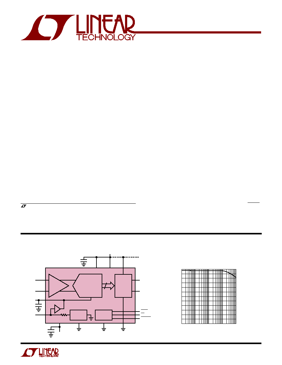
12-BIT ADC
12
5V
OPTIONAL
3V LOGIC
SUPPLY
10
µ
F
AV
DD
DV
DD
OV
DD
OGND
1412 TA01
DGND
D11 (MSB)
D0 (LSB)
BUSY
S/H
BUFFER
LTC1412
4.0625V
2k
≠ 5V
2.5V
REFERENCE
TIMING AND
LOGIC
OUTPUT
BUFFERS
∑
∑
∑
CS
CONVST
AGND
V
SS
10
µ
F
10
µ
F
V
REF
COMP
A
IN
≠
A
IN
+
Effective Bits and Signal-to-Noise + Distortion
vs Input Frequency
INPUT FREQUENCY (Hz)
2
EFFECTIVE NUMBER OF BITS
4
6
8
10
1k
100k
1M
10M
1412 G01
0
10k
12
S/(N + D) (dB)
62
74
56
68
s
Telecommunications
s
Digital Signal Processing
s
Mulitplexed Data Acquisition Systems
s
High Speed Data Acquisition
s
Spectrum Analysis
s
Imaging Systems
APPLICATIO
N
S
U
, LTC and LT are registered trademarks of Linear Technology Corporation.
s
Sample Rate: 3Msps
s
72dB S/(N + D) and 82dB SFDR at Nyquist
s
±
0.35LSB INL and
±
0.25LSB DNL (Typ)
s
Power Dissipation: 150mW
s
External or Internal Reference Operation
s
True Differential Inputs Reject Common Mode Noise
s
40MHz Full Power Bandwidth Sampling
s
±
2.5V Bipolar Input Range
s
No Pipeline Delay
s
28-Pin SSOP Package
2
LTC1412
ABSOLUTE
M
AXI
M
U
M
RATINGS
W
W
W
U
PACKAGE/ORDER I
N
FOR
M
ATIO
N
W
U
U
AV
DD
= DV
DD
= V
DD
(Notes 1, 2)
Supply Voltage (V
DD
) ................................................. 6V
Negative Supply Voltage (V
SS
)................................. ≠ 6V
Total Supply Voltage (V
DD
to V
SS
) .......................... 12V
Analog Input Voltage
(Note 3) ......................... (V
SS
≠ 0.3V) to (V
DD
+ 0.3V)
Digital Input Voltage (Note 4) .......... (V
SS
≠ 0.3V) to 10V
Digital Output Voltage ........ (V
SS
≠ 0.3V) to (V
DD
+ 0.3V)
Power Dissipation .............................................. 500mW
Operating Temperature Range
LTC1412C................................................ 0
∞
C to 70
∞
C
LTC1412I ............................................ ≠ 40
∞
C to 85
∞
C
Storage Temperature Range ................. ≠ 65
∞
C to 150
∞
C
Lead Temperature (Soldering, 10 sec).................. 300
∞
C
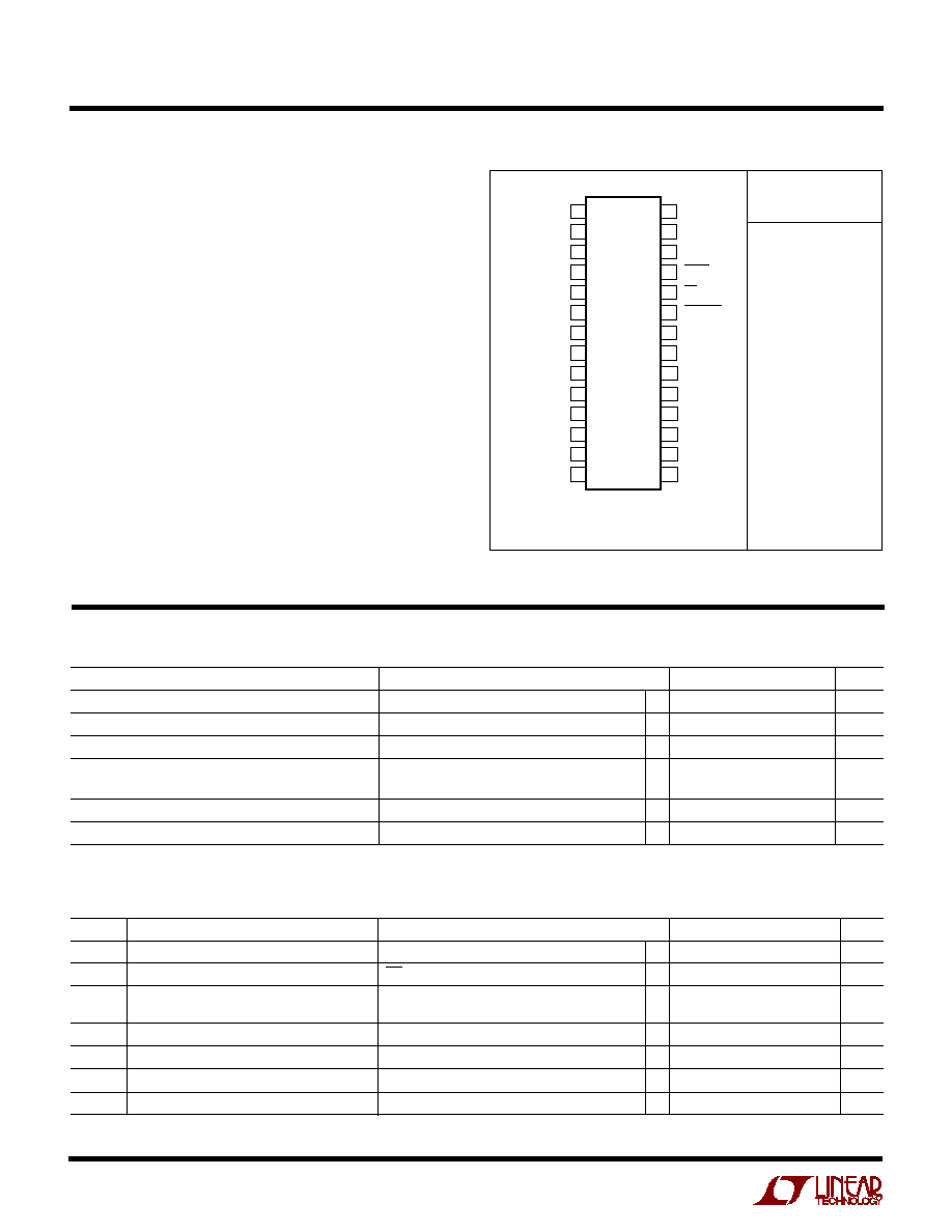
ORDER PART
NUMBER
T
JMAX
= 110
∞
C,
JA
= 95
∞
C/ W
1
2
3
4
5
6
7
8
9
10
11
12
13
14
TOP VIEW
G PACKAGE
28-LEAD PLASTIC SSOP
28
27
26
25
24
23
22
21
20
19
18
17
16
15
A
IN
+
A
IN
≠
V
REF
REFCOMP
AGND
D11 (MSB)
D10
D9
D8
D7
D6
D5
D4
DGND
AV
DD
DV
DD
V
SS
BUSY
CS
CONVST
DGND
DV
DD
OV
DD
OGND
D0
D1
D2
D3
Consult factory for Military grade parts.
LTC1412CG
LTC1412IG
SYMBOL
PARAMETER
CONDITIONS
MIN
TYP
MAX
UNITS
V
IN
Analog Input Range (Note 9)
4.75V
V
DD
5.25V, ≠ 5.25V
V
SS
≠ 4.75V
q
±
2.5
V
I
IN
Analog Input Leakage Current
CS = High
q
±
1
µ
A
C
IN
Analog Input Capacitance
Between Conversions
10
pF
During Conversions
4
pF
t
ACQ
Sample-and-Hold Acquisition Time
q
20
50
ns
t
AP
Sample-and-Hold Aperture Delay Time
≠ 0.5
ns
t
jitter
Sample-and-Hold Aperture Delay Time Jitter
1
ps
RMS
CMRR
Analog Input Common Mode Rejection Ratio
≠ 2.5V < (A
IN
≠
= A
IN
) < 2.5V
63
dB
With internal reference (Notes 5, 6)
C
C
HARA TERISTICS
CO
U
VERTER
PARAMETER
CONDITIONS
MIN
TYP
MAX
UNITS
Resolution (No Missing Codes)
q
12
Bits
Integral Linearity Error
(Note 7)
q
±
0.35
±
1
LSB
Differential Linearity Error
q
±
0.25
±
1
LSB
Offset Error
(Note 8)
±
2
±
6
LSB
q
±
8
LSB
Full-Scale Error
±
15
LSB
Full-Scale Tempco
I
OUT(REF)
= 0
q
±
15
ppm/
∞
C
PUT
U
I
A
A
U
LOG
(Note 5)
3
LTC1412
(Note 5)
SYMBOL
PARAMETER
CONDITIONS
MIN
TYP
MAX
UNITS
S/(N + D) Signal-to-Noise Plus Distortion Ratio
100kHz Input Signal
72.5
dB
1.465MHz Input Signal
70
72
dB
THD
Total Harmonic Distortion
100kHz Input Signal, First 5 Harmonics
≠ 90
dB
1.465MHz Input Signal, First 5 Harmonics
≠ 80
dB
SFDR
Spurious Free Dynamic Range
1.465MHz Input Signal
82
dB
IMD
Intermodulation Distortion
f
IN1
= 29.37kHz, f
IN2
= 32.446kHz
≠ 84
dB
Full Power Bandwidth
40
MHz
Full Linear Bandwidth
S/(N + D)
68dB
4
MHz
ACCURACY
IC
DY
U
W
A
SYMBOL
PARAMETER
CONDITIONS
MIN
TYP
MAX
UNITS
V
DD
Positive Supply Voltage
(Note 10)
4.75
5.25
V
V
SS
Negative Supply Voltage
(Note 10)
≠ 4.75
≠ 5.25
V
I
DD
Positive Supply Current
CS High
q
12
16
mA
I
SS
Negative Supply Current
CS High
q
18
28
mA
P
D
Power Dissipation
q
150
220
mW
(Note 5)
I TER AL REFERE CE CHARACTERISTICS
U
U
U
PARAMETER
CONDITIONS
MIN
TYP
MAX
UNITS
V
REF
Output Voltage
I
OUT
= 0
2.480
2.500
2.520
V
V
REF
Output Tempco
I
OUT
= 0
±
15
ppm/
∞
C
V
REF
Line Regulation
4.75V
V
DD
5.25V
0.01
LSB/ V
≠ 5.25V
V
SS
≠ 4.75V
0.01
LSB/ V
V
REF
Output Resistance
0.1mA
I
OUT
0.1mA
2
k
COMP Output Voltage
I
OUT
= 0
4.06
V
POWER REQUIRE E TS
W
U
(Note 5)
SYMBOL
PARAMETER
CONDITIONS
MIN
TYP
MAX
UNITS
V
IH
High Level Input Voltage
V
DD
= 5.25V
q
2.4
V
V
IL
Low Level Input Voltage
V
DD
= 4.75V
q
0.8
V
I
IN
Digital Input Current
V
IN
= 0V to V
DD
q
±
10
µ
A
C
IN
Digital Input Capacitance
1.4
pF
V
OH
High Level Output Voltage
V
DD
= 4.75V, I
O
= ≠ 10
µ
A
4.75
V
V
DD
= 4.75V, I
O
= ≠ 200
µ
A
q
4.0
4.71
V
V
OL
Low Level Output Voltage
V
DD
= 4.75V, I
O
= 160
µ
A
0.05
V
V
DD
= 4.75V, I
O
= 1.6mA
q
0.10
0.4
V
I
OZ
Hi-Z Output Leakage D11 to D0
V
OUT
= 0V to V
DD
, CS High
q
±
10
µ
A
C
OZ
Hi-Z Output Capacitance D11 to D0
CS High (Note 9)
7
pF
I
SOURCE
Output Source Current
V
OUT
= 0V
≠ 10
mA
(Note 5)
DIGITAL I PUTS A
N
D OUTPUTS
U
U
4
LTC1412
TI I G CHARACTERISTICS
W U
(Note 5)
SYMBOL
PARAMETER
CONDITIONS
MIN
TYP
MAX
UNITS
f
SAMPLE(MAX)
Maximum Sampling Frequency
q
3
MHz
t
THROUGHPUT
Throughput Time (Acquisition + Conversion)
q
333
ns
t
CONV
Conversion Time
q
240
283
ns
t
ACQ
Acquisition Time
q
20
50
ns
t
1
CS
to CONVST
Setup Time
(Notes 9, 10)
q
5
ns
t
2
CONVST
Low Time
(Note 10)
q
20
ns
t
3
CONVST to BUSY Delay
C
L
= 25pF
5
ns
q
20
ns
t
4
Data Ready Before BUSY
≠ 20
0
20
ns
q
≠ 25
25
ns
t
5
Delay Between Conversions
(Note 10)
q
50
ns
t
6
Data Access Time After CS
C
L
= 25pF
10
35
ns
q
45
ns
t
7
Bus Relinquish Time
8
30
ns
LTC1412C
q
35
ns
LTC1412I
q
40
ns
t
8
CONVST High Time
q
20
ns
t
9
Aperture Delay of Sample-and-Hold
≠ 1
ns
The
q
denotes specifications which apply over the full operating
temperature range; all other limits and typicals T
A
= 25
∞
C.
Note 1: Absolute Maximum Ratings are those values beyond which the life
of a device may be impaired.
Note 2: All voltage values are with respect to ground with DGND and
AGND wired together (unless otherwise noted).
Note 3: When these pin voltages are taken below V
SS
or above V
DD
, they
will be clamped by internal diodes. This product can handle input currents
greater than 100mA below V
SS
or above V
DD
without latchup.
Note 4: When these pin voltages are taken below V
SS
they will be clamped
by internal diodes. This product can handle input currents greater than
100mA below V
SS
without latchup. These pins are not clamped to V
DD
.
Note 5: V
DD
= 5V, f
SAMPLE
= 3MHz and t
r
= t
f
= 5ns unless otherwise
specified.
Note 6: Linearity, offset and full-scale specifications apply for a single-
ended A
IN
input with A
IN
≠
grounded.
Note 7: Integral nonlinearity is defined as the deviation of a code from a
straight line passing through the actual endpoints of the transfer curve.
The deviation is measured from the center of the quantization band.
Note 8: Bipolar offset is the offset voltage measured from ≠ 0.5LSB
when the output code flickers between 0000 0000 0000 and
1111 1111 1111.
Note 9: Guaranteed by design, not subject to test.
Note 10: Recommended operating conditions.
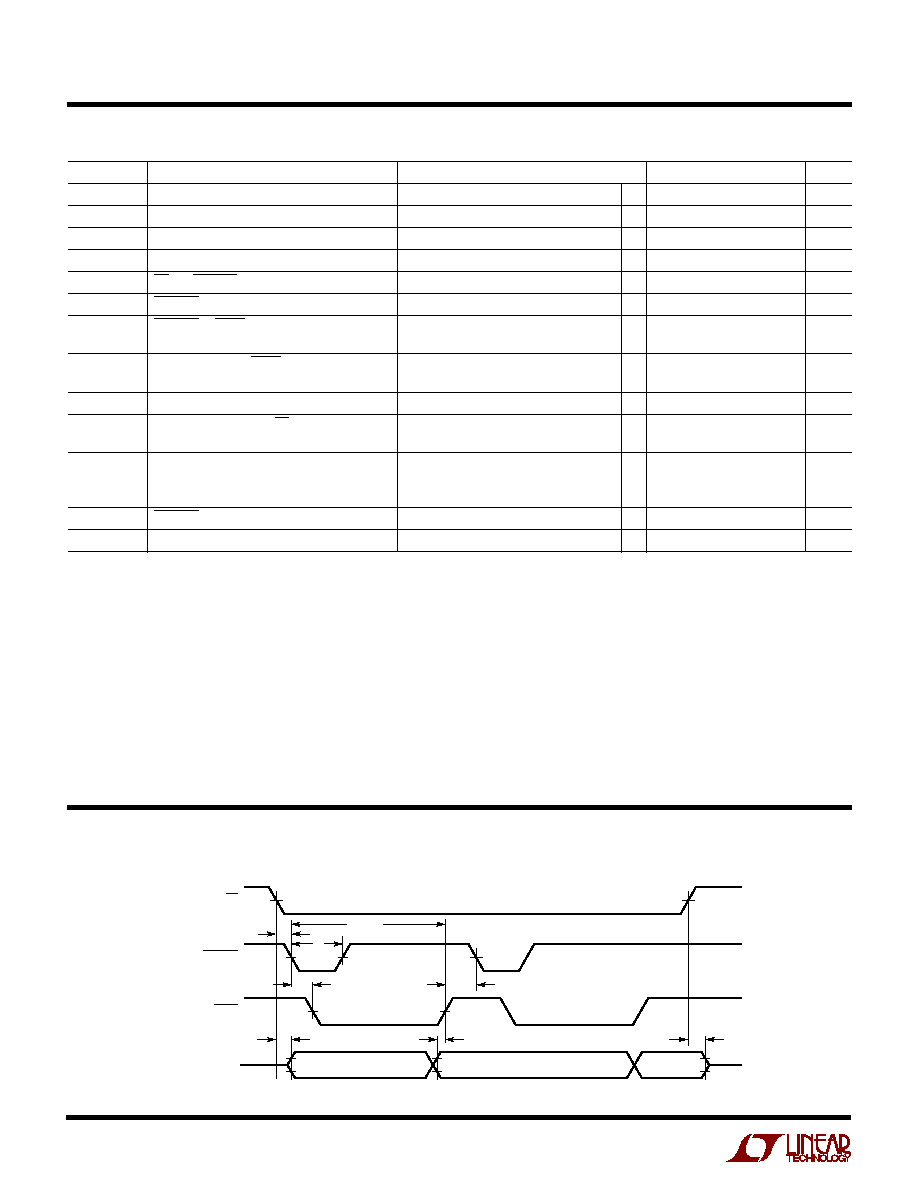
TI I G DIAGRA
U
W
W
DATA (N ≠ 1)
DB11 TO DB0
CONVST
BUSY
CS
1412 TD
t
2
t
CONV
t
3
t
1
t
5
t
4
t
6
t
7
DATA N
DB11 TO DB0
DATA (N + 1)
DB11 TO DB0
DATA

5
LTC1412
TYPICAL PERFOR A CE CHARACTERISTICS
U
W
INPUT FREQUENCY (Hz)
10
≠120
DISTORTION (dB)
≠ 40
≠ 20
0
100
1k
10k
1412 G03
≠ 60
≠ 80
≠100
3RD
THD
2ND
Distortion vs Input Frequency
Spurious-Free Dynamic Range
vs Input Frequency
INPUT FREQUENCY (Hz)
2
EFFECTIVE NUMBER OF BITS
4
6
8
10
1k
100k
1M
10M
1412 G01
0
10k
12
S/(N + D) (dB)
62
74
56
68
S/(N + D) and Effective Number of
Bits vs Input Frequency
FREQUENCY (Hz)
10K
≠ 60
SPURIOUS-FREE DYNAMIC RANGE (dB)
≠ 50
≠ 40
≠ 30
≠ 20
100K
1M
10M
1412 G04
≠ 70
≠ 80
≠ 90
≠100
≠10
0
Signal-to-Noise Ratio
vs Input Frequency
INPUT FREQUENCY (Hz)
10k
40
SIGNAL-TO-NOISE RATIO (dB)
60
80
100k
1M
10M
1412 G02
20
30
50
70
10
0
Integral Nonlinearity
vs Output Code
OUTPUT CODE
0
≠1.0
INL (LSBs)
≠ 0.5
0
0.5
1.0
512 1024 1536 2048
1412 G07
2560 3072 3584 4096
Intermodulation Distortion Plot
FREQUENCY (kHz)
0
200
400
600
800 1000 1200 1400
≠110
AMPLITUDE (dB)
≠100
≠ 80
≠ 70
≠ 90
≠ 60
≠ 50
≠ 40
≠ 30
0
1412 G05
≠20
≠10
f
SMPL
= 3MHz
f
IN1
= 85.693359kHz
f
IN2
= 114.990234kHz
Differential Nonlinearity
vs Output Code
OUTPUT CODE
0
≠1.0
DNL (LSBs)
≠ 0.5
0
0.5
1.0
512 1024 1536 2048
1412 G06
2560 3072 3584 4096
FREQUENCY (kHz)
0
200
400
600
800 1000 1200 1400
≠120
AMPLITUDE (dB)
≠100
≠ 80
≠ 60
≠ 40
0
1412 F02a
≠20
f
SMPL
= 3Msps
f
IN
= 97.412kHz
SFDR = 93.3dB
SINAD = 73dB
Nonaveraged, 4096 Point FFT,
Input Frequency = 100kHz
FREQUENCY (kHz)
0
200
400
600
800 1000 1200 1400
≠120
AMPLITUDE (dB)
≠100
≠ 80
≠ 60
≠ 40
0
1412 F02B
≠20
f
SMPL
= 3Msps
f
IN
= 1.419kHz
SFDR = 83dB
SINAD = 72.5dB
SNR = 73db
Nonaveraged, 4096 Point FFT,
Input Frequency = 1.45kHz