 | ÐлекÑÑоннÑй компоненÑ: LTC2922IF | СкаÑаÑÑ:  PDF PDF  ZIP ZIP |
2921/22fa.pm65
LTC2921/LTC2922 Series
1
29212fa
APPLICATIO S
U
FEATURES
DESCRIPTIO
U
TYPICAL APPLICATIO
U
2921/22 TA01
100
10
LTC2921
V
CC
SENSE
100
100
4.7k
49.9k
49.9k
169k
243k
V
OUT
V
FB
V
OUT
V
FB
V
OUT
V
FB
10
10
V1
V2
V3
V4
GATE
PG
GND
TIMER
Si1012R
CBRST
5V SUPPLY
3.3V SUPPLY
2.5V SUPPLY
Si2316DS
Si2316DS
Si2316DS
WSL1206
0.05
0.22
µ
F
5V
LOAD
3.3V
LOAD
2.5V
LOAD
RESET
0.47
µ
F
DC/DC
CONVERTER
DC/DC
CONVERTER
DC/DC
CONVERTER
100k
D1
D2
D3
S1
S2
S3
CIRCUIT BREAKER
RESET CONTROL
t
GATE
~ 500ms
t
TIMER
~ 130ms
s
Desktop Computers
s
Plug-In Cards
s
Telecom Infrastructure
s
Supply Sequencing
s
Instruments
s
Tracks Multiple Supplies with MOSFET Switches
s
Monitors 5 Input Voltages Including V
CC
s
Guaranteed Threshold Accuracy:
±
1% at 0.5V
s
Automatic Remote Sense Switching
s
Adjustable Supply Ramp Rate
s
Overvoltage Monitor
s
Adjustable Electronic Circuit Breaker
s
Adjustable Power-Good Delay
s
Available for V
CC
Supply Voltages of 5V, 3.3V and 2.5V
s
Available in 16-Pin Narrow SSOP (LTC2921 Series)
and 20-Pin TSSOP (LTC2922 Series)
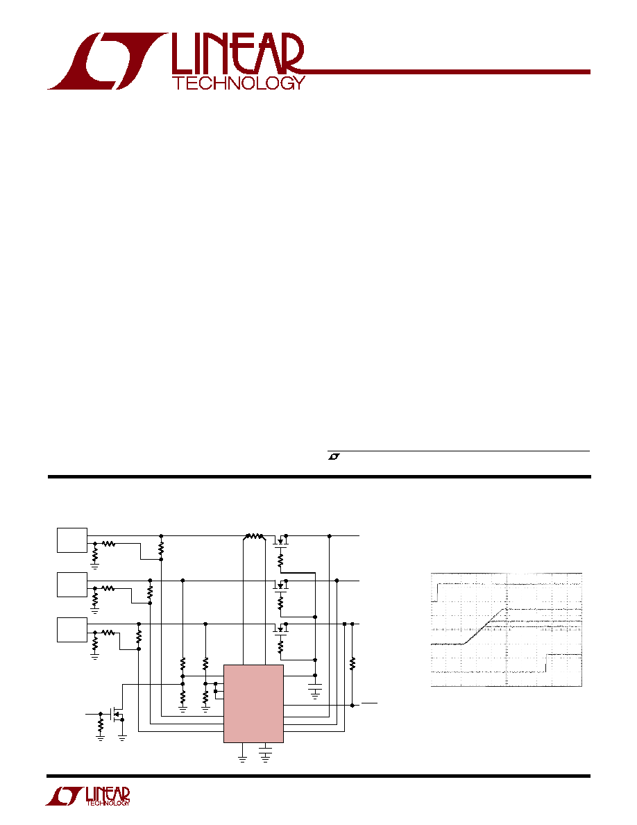
Power Supply Tracker
with Input Monitors
The LTC
®
2921 and LTC2922 monitor up to five supplies
and force them to track on power-up in multiple supply
systems. Using external N-channel pass transistors, the
supplies can be ramped up at an adjustable rate. Auto-
matic remote sense switching allows the DC/DC convert-
ers to compensate for series voltage drops in the wiring.
An incorrect level on one or more of the supplies triggers
disconnect of all supplies. Tight 1% accuracy and glitch
immunity on the low 0.5V monitoring level ensure no false
error disconnects.
The LTC2921 and LTC2922 each feature an adjustable
electronic circuit breaker to protect the V
CC
supply against
short circuits. Capacitance at the TIMER pin programs the
delays in the monitoring sequence.
The LTC2921 includes three remote sense switches in a
16-pin narrow SSOP package, while the LTC2922 includes
five remote sense switches in a 20-pin TSSOP package.
Both parts are available for V
CC
supply voltages of 5V,
3.3V, and 2.5V.
, LTC and LT are registered trademarks of Linear Technology Corporation.
Three-Supply Tracker and Monitor (5V, 3.3V, 2.5V)
Load Voltage Ramp-Up and
Power-Good Activation
2921/22 TA01b
2.5V SUPPLY
2V/DIV
PG
2V/DIV
5V LOAD
3.3V LOAD
2.5V LOAD
5V SUPPLY AT 5V
3.3V SUPPLY AT 3.3V
100ms/DIV
OUTPUTS
2V/DIV

LTC2921/LTC2922 Series
2
29212fa
SYMBOL
PARAMETER
CONDITIONS
MIN
TYP
MAX
UNITS
Supply Pin
V
CC
Supply Voltage
Typical Operating Range
LTC2921/LTC2922
4.50
5.00
5.50
V
LTC2921-3.3/LTC2922-3.3
2.97
3.30
3.63
V
LTC2921-2.5/LTC2922-2.5
2.37
2.50
2.63
V
I
CC
Supply Current
2
mA
V
CC(MON)
Supply Monitor Threshold Voltage
LTC2921/LTC2922
q
4.285
4.350
4.415
V
LTC2921-3.3/LTC2922-3.3
q
2.828
2.871
2.914
V
LTC2921-2.5/LTC2922-2.5
q
2.265
2.300
2.335
V
V
CC(OV)
Supply Overvoltage Threshold
LTC2921/LTC2922
q
5.82
6.13
6.43
V
LTC2921-3.3/LTC2922-3.3
q
3.84
4.04
4.24
V
LTC2921-2.5/LTC2922-2.5
q
3.08
3.24
3.40
V
V
CC
Supply Voltage ...................................... 0.3V to 7V
V1, V2, V3, V4 Voltages ............................... 0.3V to 7V
SENSE Voltage ............................................ 0.3V to 7V
TIMER Voltage ............................. 0.3V to (V
CC
+ 0.3V)
Charge Pumped Output Voltages
GATE, PG ............................................ 0.3V to 12.2V
Switch Voltages
S0, D0, S4, D4 (LTC2922 Series) ............ 0.3V to 7V
S1, D1, S2, D2, S3, D3 ............................ 0.3V to 7V
ORDER PART
NUMBER
T
JMAX
= 125
°
C,
JA
= 110
°
C/W
ABSOLUTE AXI U
RATI GS
W
W
W
U
PACKAGE/ORDER I FOR ATIO
U
U
W
(Note 1)
ELECTRICAL CHARACTERISTICS
Consult LTC Marketing for parts specified with wider operating temperature ranges.
Switch Currents (DC, RMS)
S0, D0, S4, D4 (LTC2922 Series) ..................... 30mA
S1, D1, S2, D2, S3, D3 ..................................... 30mA
Operating Ambient Temperature Range
LTC2921C/LTC2922C .............................. 0
°
C to 70
°
C
LTC2921I/LTC2922I ............................40
°
C to 85
°
C
Junction Temperature (Note 2) ............................. 125
°
C
Storage Temperature Range ..................65
°
C to 150
°
C
Lead Temperature (Soldering, 10 sec).................. 300
°
C
ORDER PART
NUMBER
LTC2922CF
LTC2922CF-3.3
LTC2922CF-2.5
LTC2922IF
LTC2922IF-3.3
LTC2922IF-2.5
T
JMAX
= 125
°
C,
JA
= 90
°
C/W
TOP VIEW
GN PACKAGE
16-LEAD NARROW PLASTIC SSOP
1
2
3
4
5
6
7
8
16
15
14
13
12
11
10
9
V1
V2
V3
V4
S3
D3
S2
D2
TIMER
V
CC
SENSE
GATE
PG
GND
D1
S1
1
2
3
4
5
6
7
8
9
10
TOP VIEW
20
19
18
17
16
15
14
13
12
11
SO
TIMER
V1
V2
V3
V4
S4
D4
S3
D3
D0
V
CC
SENSE
GATE
PG
GND
D1
S1
D2
S2
F PACKAGE
20-LEAD PLASTIC TSSOP
LTC2921CGN
LTC2921CGN-3.3
LTC2921CGN-2.5
LTC2921IGN
LTC2921IGN-3.3
LTC2921IGN-2.5
GN PART MARKING
2921
292133
292125
2921I
921I33
921I25
The
q
denotes the specifications which apply over the full operating
temperature range, otherwise specifications are at T
A
= 25
°
C. V
CC
= 5V for LTC2921/LTC2922, V
CC
= 3.3V for
LTC2921-3.3/LTC2922-3.3, and V
CC
= 2.5V for LTC2921-2.5/LTC2922-2.5, unless otherwise noted.
LTC2921/LTC2922 Series
3
29212fa
The
q
denotes the specifications which apply over the full operating
temperature range, otherwise specifications are at T
A
= 25
°
C. V
CC
= 5V for LTC2921/LTC2922, V
CC
= 3.3V for
LTC2921-3.3/LTC2922-3.3, and V
CC
= 2.5V for LTC2921-2.5/LTC2922-2.5, unless otherwise noted.
ELECTRICAL CHARACTERISTICS
Note 1: Absolute Maximum Ratings are those values beyond which the life
of a device may be impaired.
Note 2: T
J
is calculated from the ambient temperature T
A
and power
dissipation P
D
as follows:
LTC2921 Series: T
J
= T
A
+ (P
D
· 110
°
C/W)
LTC2922 Series: T
J
= T
A
+ (P
D
· 90
°
C/W)
Note 3: This specification applies to all switches, and is measured with
V
S
< V
D
.
Note 4: The PG pin will rise to approximately the same voltage as the
GATE pin when not pulled up or pulled down by external resistance.
SYMBOL
PARAMETER
CONDITIONS
MIN
TYP
MAX
UNITS
V
CC(UVLO)
Supply Undervoltage Lockout
V
CC
Rising
q
2.08
2.20
2.30
V
V
CC(UVH)
Supply Undervoltage Hysteresis
V
CC
Falling
120
mV
Electronic Circuit Breaker
V
SENSE
Circuit Breaker Trip Voltage
V
SENSE
= V
CC
- V
SENSE
q
45
50
55
mV
I
SENSE
SENSE Pin Input Current
150
500
nA
t
V1(DLY)
Circuit Breaker Trip Delay Time
V
CC
- V
SENSE
= 150mV
LTC2921/LTC2922
0.5
1.5
3.0
µ
s
LTC2921-3.3/LTC2922-3.3
0.5
1.5
3.0
µ
s
LTC2921-2.5/LTC2922-2.5
0.5
1.5
6.0
µ
s
t
V1(RST)
Circuit Breaker Reset Pulse Width
Guaranteed Not to Reset
q
50
µ
s
Guaranteed to Reset
q
150
µ
s
V
V1(RST)
Circuit Breaker Reset Threshold Voltage
q
0.490
0.500
0.510
V
Monitor Inputs
V
MON
V1-V4 Monitor Threshold Voltages
0.495
0.500
0.505
V
q
0.492
0.500
0.508
V
V
OV
V1-V4 Overvoltage Thresholds
q
0.665
0.700
0.735
V
I
MON
V1-V4 Input Currents
±
0.1
µ
A
TIMER Pin
V
TIMER(TH)
TIMER Ramp Threshold Voltage
q
1.15
1.20
1.25
V
I
TIMER(PU)
TIMER Pull-Up Current
V
TIMER
= 1V
q
1.3
2.0
2.5
µ
A
I
TIMER(PD)
TIMER Pull-Down Current
V
CC
= 2.35V, V
TIMER
= 0.4V
100
µ
A
V
TIMER(CLR)
TIMER Cleared Threshold Voltage
V
TIMER
Falling
150
250
mV
GATE Pin
V
GATE
GATE Drive Output Voltage
LTC2921/LTC2922
q
10.0
11.1
12.2
V
LTC2921-3.3/LTC2922-3.3
q
8.4
9.1
9.8
V
LTC2921-2.5/LTC2922-2.5
q
6.1
6.8
7.5
V
I
GATE(PU)
GATE Pull-Up Current
V
GATE
= V
CC
q
6.5
10.0
12.5
µ
A
I
GATE(PD)
GATE Pull-Down Current
V
CC
= 2.35V, V
GATE
= 2.35V
10
mA
Remote Sense Switches
R
DS(FB)
Feedback Switch Resistances (Note 3)
V
D
= V
CC
q
2
10
PG Pin
I
PG(PU)
PG Pull-Up Current
V
PG
= V
CC
q
2.6
4.0
5.0
µ
A
I
PG(PD)
PG Pull-Down Current
V
CC
= 2.35V, V
PG
= 2.35V
10
mA
V
PG(OL)
PG Output Low Voltage
V
CC
= 2.35V, I
PG
= 5mA
q
0.4
V
V
PG
PG Output Voltage (Note 4)
LTC2921/LTC2922
q
10.0
11.1
12.2
V
LTC2921-3.3/LTC2922-3.3
q
8.4
9.1
9.8
V
LTC2921-2.5/LTC2922-2.5
q
6.1
6.8
7.5
V
LTC2921/LTC2922 Series
4
29212fa
V
CC
(V)
2.0
I
CC
(mA)
3.0
4.0 4.5
6.5
2921/2 G01
2.5
3.5
5.0 5.5 6.0
3.00
2.75
2.50
2.25
2.00
1.75
1.50
TEMPERATURE (
°
C)
50
I
CC
(mA)
2.6
2.4
2.2
2.0
1.8
10
50
2921/2 G02
2921/2 G03
30
10
30
70
90
BREAKER TRIP (mV)
2921/2 G05
2921/2 G04
55
50
45
TEMPERATURE (
°
C)
50
I
SENSE
(nA)
250
200
150
100
50
0
10
30
50
2921/2 G06
30
10
70
90
TEMPERATURE (
°
C)
50
10
30
50
30
10
70
90
MONITOR INPUT THRESHOLD (V)
0.505
0.500
0.495
TEMPERATURE (
°
C)
10
30
50
30
10
70
90
50
TEMPERATURE (
°
C)
10
30
50
30
10
70
90
50
2.0
3.0
4.0 4.5
6.5
2.5
3.5
5.0 5.5 6.0
V
CC
(V)
TIMER TRIP VOLTAGE (V)
2921/2 G07
1.21
1.20
1.19
2.5
2.4
2.3
2.2
2.1
2.0
1.9
1.8
1.7
1.6
1.5
TEMPERATURE (
°
C)
50
CURRENT (
µ
A)
70
2921/2 G08
10
30
30
10
50
90
PULL-DOWN CURRENT (
µ
A)
2921/2 G09
170
165
160
155
150
145
140
LTC2921-2.5
LTC2922-2.5
LTC2921-3.3
LTC2922-3.3
LTC2921
LTC2922
LTC2921-2.5
LTC2922-2.5
LTC2921-3.3
LTC2922-3.3
LTC2921
LTC2922
PG SIGNAL ASSERTED
PG SIGNAL ASSERTED
MONITOR INPUT OVERDRIVE (mV)
0
MONITOR TRIP DELAY (
µ
s)
100
80
60
40
20
0
40
80
100
20
60
120
140
LTC2921-2.5
LTC2922-2.5
LTC2921/LTC2922
LTC2921-3.3/LTC2922-3.3
V
SENSE
= V
CC
V
TIMER
= 1V
V
TIMER
= 0.4V
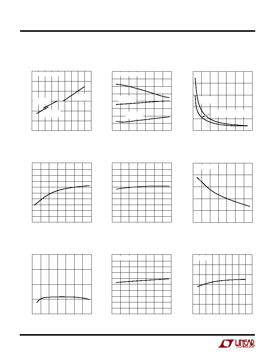
Supply Current vs Supply Voltage
Supply Current vs Temperature
Monitor Trip Delay vs
Monitor Input Overdrive
Monitor Input Threshold vs
Temperature
Circuit Breaker Trip Voltage vs
Temperature
SENSE Input Current
vs Temperature
TIMER Trip Voltage
vs Temperature
TIMER Pull-Up Current
vs Temperature
TIMER Pull-Down Current
vs Supply Voltage
TYPICAL PERFOR A CE CHARACTERISTICS
U
W
Specifications are at T
A
= 25
°
C unless otherwise noted.
LTC2921/LTC2922 Series
5
29212fa
V
CC
(V)
2.0
3.0
4.0 4.5
6.5
2.5
3.5
5.0 5.5 6.0
GATE VOLTAGE (V)
12
11
10
9
8
7
6
GATE VOLTAGE (V)
12
11
10
9
8
7
6
LTC2921-2.5
LTC2922-2.5
LTC2921-3.3
LTC2922-3.3
V
CC
(V)
2.0
3.0
4.0 4.5
6.5
2.5
3.5
5.0 5.5 6.0
PG (V)
12
11
10
9
8
7
6
TEMPERATURE (
°
C)
50
10
50
2921/2 G11
2921/2 G10
30
10
30
70
90
LOAD CURRENT (
µ
A)
4
0
1
2
3
7
8
2921/2 G12
6
5
9
10
GATE VOLTAGE (V)
12
10
8
6
4
2
0
CURRENT (
µ
A)
5.5
5.0
4.5
4.0
3.5
3.0
2.5
TEMPERATURE (
°
C)
50
10
50
2921/2 G15
30
10
30
70
90
TEMPERATURE (
°
C)
50
10
50
2921/2 G13
30
10
30
70
90
2921/2 G14
CURRENT (
µ
A)
GATE LOAD = 1000pF || 10M
PG LOAD = 2k
TO V
CC
V
CC
BYPASS CAP = 1
µ
F
GATE LOAD = 1000pF || 10M
PG LOAD = 2k
TO V
CC
V
CC
BYPASS CAP = 1
µ
F
LTC2921
LTC2922
LTC2921-2.5
LTC2922-2.5
LTC2921-3.3
LTC2922-3.3
LTC2921
LTC2922
LTC2921-2.5
LTC2922-2.5
LTC2921-2.5
LTC2922-2.5
LTC2921-3.3
LTC2922-3.3
LTC2921-3.3
LTC2922-3.3
LTC2921
LTC2922
LTC2921
LTC2922
11.5
11.0
10.5
10.0
9.5
9.0
8.5
V
GATE
= V
CC
V
PG
= V
CC
GATE LOAD = 1000pF || 10M
PG LOAD = 2k
TO V
CC
V
CC
BYPASS CAP = 1
µ
F
GATE LOAD = 1000pF || 10M
PG LOAD = 1000pF || 10M
V
CC
BYPASS CAP = 1
µ
F
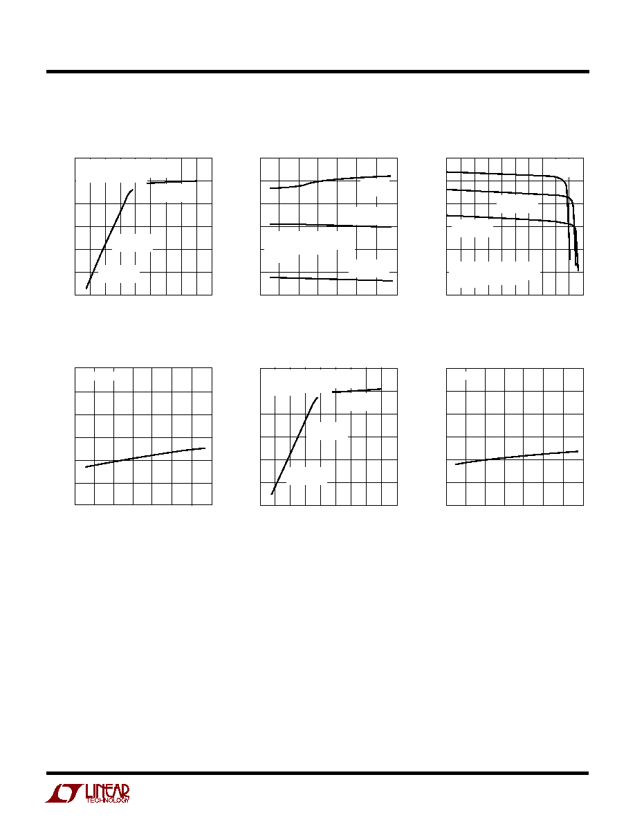
Gate Voltage vs Supply Voltage
Gate Voltage vs Temperature
Gate Voltage vs Load Current
GATE Pull-Up Current
vs Temperature
PG Pull-Up Current vs
Temperature
PG Voltage vs Supply Voltage
TYPICAL PERFOR A CE CHARACTERISTICS
U
W
Specifications are at T
A
= 25
°
C unless otherwise noted.