1
RH1021-7
Precision 7V Reference
The RH1021-7 is a precision 7V reference with ultralow
drift and noise, extremely good long-term stability and
almost total immunity to input voltage variations. The
reference output will source and sink up to 10mA. This
reference can also be used as a shunt regulator
(2-terminal Zener). Unique circuit design makes the
RH1021-7 the first IC reference to offer ultralow drift
without the use of high power on-chip heaters.
The wafer lots are processed to Linear Technology's in-
house Class S flow to yield circuits usable in stringent
military applications.
Input Voltage ........................................................... 40V
Input/Output Voltage Differential ............................. 35V
Output to Ground Voltage
(Shunt Mode Current Limit) ............................... 10V
Output Short-Circuit Duration
V
IN
= 35V ........................................................ 10 sec
V
IN
20V ................................................... Indefinite
Operating Temperature Range .............. ≠ 55∞C to 125∞C
Storage Temperature Range ................. ≠ 65∞C to 150∞C
Lead Temperature (Soldering, 10 sec) .................. 300∞C
ABSOLUTE
M
AXI
M
U
M
RATINGS
W
W
W
U
DESCRIPTIO
N
U
BUR -I CIRCUIT
U
U
PACKAGE/ORDER I
N
FOR
M
ATIO
N
W
U
U
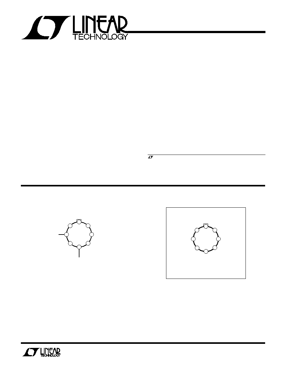
8
7
6
5
2
20V
1
4
≠20V
RH1021-7
3
TOP VIEW
NC*
NC*
NC*
V
IN
V
OUT
NC*
NC*
GND
8
7
6
5
2
1
4
H PACKAGE
8-LEAD TO-5 METAL CAN
3
* Connected internally. Do not connect external
circuitry to these pins.
, LTC and LT are registered trademarks of Linear Technology Corporation.

2
RH1021-7
10Krad(Si) 20Krad(Si) 50Krad(Si) 100Krad(Si) 200Krad(Si)
SYMBOL PARAMETER
CONDITIONS
NOTES MIN
MAX
MIN
MAX
MIN
MAX
MIN
MAX
MIN
MAX
UNITS
V
OUT
Output Voltage
1
6.95
7.05
6.95
7.05
6.95
7.07
6.94
7.06
6.93
7.07
V
TCV
OUT
Output Voltage
RH1021BM-7
2
5
5
5
7
10
ppm/∞C
Temperature Coefficient
RH1021DM-7
2
20
20
20
22
25
ppm/∞C
V
OUT
Line Regulation
8.5V V
IN
12V
3
4
4
4.5
5
6
ppm/V
V
IN
12V V
IN
40V
3
2
2
2
2
3
ppm/V
V
OUT
Load Regulation
0 I
OUT
10mA
3,8
25
25
25
25
25
ppm/mA
I
OUT
(Sourcing Current)
Load Regulation
1.2mA I
OUT
10mA
3,4
100
100
100
100
150
ppm/mA
(Shunt Mode)
I
MIN
Minimum Current
V
IN
Is Open
1.2
1.2
1.2
1.2
1.2
mA
(Shunt Mode)
I
S
Supply Current
1.0
1.0
1.0
1.0
1.0
mA
(Series Mode)
T
A
= 25∞C
SUB-
SUB-
SYMBOL PARAMETER
CONDITIONS
NOTES
MIN
TYP
MAX
GROUP
MIN
TYP
MAX
GROUP
UNITS
V
OUT
Output Voltage
1
6.95
7.05
1
V
TCV
OUT
Output Voltage
RH1021BM-7
2
5
2,3
ppm/∞C
Temperature Coefficient
RH1021DM-7
2
20
2,3
ppm/∞C
V
OUT
Line Regulation
8.5V V
IN
12V
3
4
1
8
2,3
ppm/V
V
IN
12V V
IN
40V
3
2
1
4
2,3
ppm/V
V
OUT
Load Regulation
0 I
OUT
10mA
3
25
1
40
2,3
ppm/mA
I
OUT
(Sourcing Current)
Load Regulation (Shunt Mode)
1.2mA I
OUT
10mA
3,4
100
1
150
2,3
ppm/mA
I
S
Supply Current (Series Mode)
1.2
1
1.5
2,3
mA
I
MIN
Minimum Current (Shunt Mode) V
IN
Is Open
1.0
1
1.2
2,3
mA
Output Voltage Noise
0.1Hz f 10Hz
5
4
µV
P-P
10Hz f 1kHz
5
4
4
µV
RMS
Long-Term Stability
T = 1000 Hrs
6
7
ppm
of V
OUT
Noncumulative
Temperature Hysteresis
T = ± 25∞C
3
ppm
of V
OUT
≠ 55∞C T
A
125∞C
(Preirradiation) (Note 9)
TABLE 1: ELECTRICAL CHARACTERISTICS
TABLE 1A: ELECTRICAL CHARACTERISTICS
(Postirradiation) (Note 7)
3
RH1021-7
TABLE 1A: ELECTRICAL CHARACTERISTICS
TABLE 2: ELECTRICAL TEST REQUIRE E TS
UW
MIL-STD-883 TEST REQUIREMENTS
SUBGROUP
Final Electrical Test Requirements (Method 5004)
1*,2,3,4
Group A Test Requirements (Method 5005)
1,2,3,4
Group B and D for Class S, and
1
Group C and D for Class B
End Point Electrical Parameters (Method 5005)
* PDA Applies to subgroup 1. See PDA Test Notes.
PDA Test Notes
The PDA is specified as 5% based on failures from group A, subgroup 1,
tests after cooldown as the final electrical test in accordance with method
5004 of MIL-STD-883. The verified failures of group A, subgroup 1, after
burn-in divided by the total number of devices submitted for burn-in in
that lot shall be used to determine the percent for the lot.
Linear Technology Corporation reserves the right to test to tighter limits
than those given.
Note 1: Output voltage is measured immediately after turn-on. Changes
due to chip warm-up are typically less than 0.005%.
Note 2: Temperature coefficient is measured by dividing the change in
output voltage over the temperature range by the change in temperature.
Separate tests are done for hot and cold; T
MIN
to 25∞C and 25∞C to T
MAX
.
Incremental slope is also measured at 25∞C.
Note 3: Line and load regulation are measured on a pulse basis. Output
changes due to die temperature change must be taken into account
separately. Package thermal resistance is 150∞C/W for the TO-5 (H)
package.
Note 4: Shunt mode regulation is measured with the input open. With the
input connected, shunt mode current can be reduced to 0mA. Load
regulation will remain the same.
Note 5: RMS noise is measured with a 2-pole highpass filter at 10Hz and a
2-pole lowpass filter at 1kHz. The resulting output is full wave rectified and
then integrated for a fixed period, making the final reading an average as
opposed to RMS. Correction factors are used to convert from average to
RMS and to correct for the nonideal bandpass of the filters. Peak-to-peak
noise is measured with a single highpass filter at 0.1Hz and a 2-pole
lowpass filter at 10Hz. The unit is enclosed in a still-air environment to
eliminate thermocouple effects on the leads. Test time is 10 seconds.
Note 6: Consult factory for units with long term stability data.
Note 7: V
IN
= 12V, I
OUT
= 0, T
A
= 25∞C, unless otherwise noted.
Note 8: I
OUT(MAX)
(Sourcing) is 5mA for exposures greater than
100Krad (Si).
Note 9: V
IN
= 12V, I
OUT
= 0, unless otherwise noted.
15V
≠15V
GND
V
IN
Information furnished by Linear Technology Corporation is believed to be accurate and reliable.
However, no responsibility is assumed for its use. Linear Technology Corporation makes no represen-
tation that the interconnection of its circuits as described herein will not infringe on existing patent rights.
TOTAL DOSE BIAS CIRCUIT
4
RH1021-7
Linear Technology Corporation
1630 McCarthy Blvd., Milpitas, CA 95035-7417
(408) 432-1900
q
FAX
: (408) 434-0507
q
TELEX
: 499-3977
©
LINEAR TECHNOLOGY CORPORATION 1990
LT/HP 0896 .5K REV A ∑ PRINTED IN USA
I.D. No. 66-10-0177 Rev. A 0896
TYPICAL PERFOR
M
A
N
CE CHARACTERISTICS
U
W
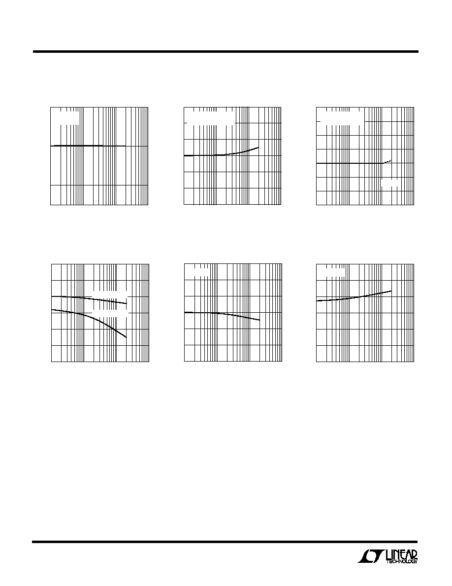
TOTAL DOSE Krad (Si)
1
LOAD REGULATION (ppm/mA)
18
16
14
12
10
8
6
4
10
100
1000
RH1021-7 G03
V
IN
= 12V
0mA
I
OUT
10mA
NOTE 8
TOTAL DOSE Krad (Si)
1
OUTPUT VOLTAGE (V)
7.01
6.99
10
100
1000
RH1021-7 G01
V
IN
= 12V
I
OUT
= 0
Output Voltage
TOTAL DOSE Krad (Si)
1
LOAD REGULATION (ppm/mA)
60
50
40
30
20
10
0
10
100
1000
RH1021-7 G02
V
IN
= OPEN
1.2mA
I
OUT
10mA
Load Regulation (Shunt Mode)
Load Regulation (Sourcing)
TOTAL DOSE Krad (Si)
1
LINE REGULATION (ppm/V)
1.0
0.5
0
≠0.5
≠1.0
≠1.5
≠2.0
10
100
1000
RH1021-7 G04
12V
V
IN
40V
8.5V
V
IN
12V
Line Regulation
Temperature Coefficient
TOTAL DOSE Krad (Si)
1
TEMPERATURE COEFFICIENT (ppm/
∞
C)
15
10
5
0
≠5
≠10
≠15
10
100
1000
RH1021-7 G05
V
IN
= 12V
TOTAL DOSE Krad (Si)
1
MINIMUM CURRENT (mA)
0.9
0.8
0.7
0.6
0.5
0.4
0.3
10
100
1000
RH1021-7 G06
V
IN
= OPEN
Minimum Current (Shunt Mode)