1
RH129
6.9V Precision Reference
Information furnished by Linear Technology Corporation is believed to be accurate and reliable.
However, no responsibility is assumed for its use. Linear Technology Corporation makes no represen-
tation that the interconnection of its circuits as described herein will not infringe on existing patent rights.
T
A
= 25∞C
SUB-
SUB-
SYMBOL PARAMETER
CONDITIONS
NOTES
MIN
TYP
MAX
GROUP
MIN
TYP
MAX
GROUP
UNITS
V
Z
Reverse Breakdown Voltage
0.6mA I
R
15mA
6.7
7.2
1
V
V
Z
Reverse Breakdown
0.6mA I
R
15mA
14
mV
I
R
Voltage Change with Current
1mA I
R
15mA
12
mV
V
Z
Temperature Coefficient
I
R
= 1mA,
RH129A
10
2, 3
ppm/∞C
Temp
RH129B
20
2, 3
ppm/∞C
RH129C
50
2, 3
ppm/∞C
Change in TC
1mA I
R
15mA
1
ppm/∞C
r
Z
Dynamic Impedance
I
R
= 1mA
2
1mA I
R
15mA
1
0.8
en
RMS Noise
10Hz f 10kHz
2
20
1
µV
V
Z
Long Term Stability
T
A
= 25∞C ± 0.1∞C,
Time
I
R
= 1mA ± 0.3%
20
ppm/kHr
TABLE 1: ELECTRICAL CHARACTERISTICS
(Preirradiation)
≠ 55∞C T
A
125∞C
Reverse Breakdown Current ................................ 30mA
Forward Current..................................................... 2mA
Operating Temperature Range ............. ≠ 55∞C to 125∞C
Storage Temperature Range ................. ≠ 65
∞
C to 150
∞
C
Lead Temperature (Soldering, 10 sec) .................. 300
∞
C
D
U
ESCRIPTIO
A
U
G
W
A
W
U
W
A
R
BSOLUTE
XI
TI
S
The RH129 precision reference features excellent stability
over a wide range of voltage, temperature and operating
current conditions. The device achieves low dynamic
impedance by incorporating a high gain shunt regulator
around the Zener. The excellent noise performance of the
device is achieved by using a buried Zener design which
eliminates surface noise usually associated with ordinary
Zeners.
The wafer lots are processed to LTC's in-house Class S
flow to yield circuits usable in stringent military applica-
tions.
, LTC and LT are registered trademarks of Linear Technology Corporation.
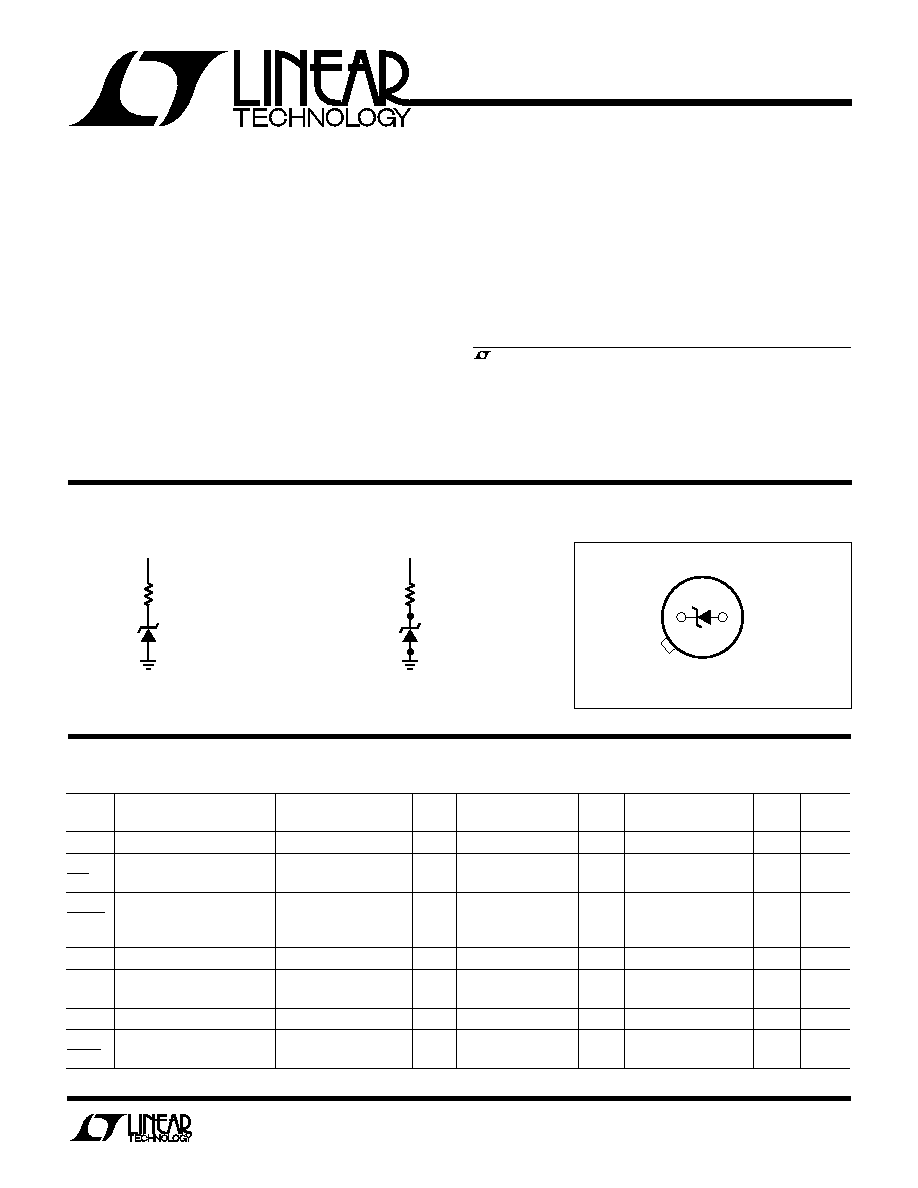
BUR -I CIRCUIT
U
U
10k
20V
RH1009 BI
PACKAGE I
N
FOR
M
ATIO
N
U
U
W
BOTTOM VIEW
2
1
H PACKAGE
2-LEAD TO-46 METAL CAN
TOTAL DOSE BIAS CIRCUIT
12.4k
15V
RH129 TDBC1

2
RH129
SYMBOL PARAMETER
CONDITIONS
NOTES MIN
MAX
MIN
MAX
MIN
MAX
MIN
MAX
MIN
MAX
UNITS
V
Z
Reverse Breakdown Voltage 0.6mV I
R
15mA
6.7
7.2
6.7
7.2
6.7
7.2
6.7
7.2
6.7
7.2
V
V
Z
Reverse Breakdown Voltage 0.6mV I
R
15mA
14
14
20
30
50
mV
I
Z
Change with Current
V
Z
Temperature Coefficient
I
R
= 1mA, RH129A
10
10
10
15
20
ppm/∞C
Temp
≠ 55∞C T
A
125∞C
RH129B
20
20
20
25
30
ppm/∞C
RH129C
50
50
50
55
60
ppm/∞C
TABLE 1A: ELECTRICAL CHARACTERISTICS
(Postirradiation) (Note 3)
50KRAD(Si)
20KRAD(Si)
10KRAD(Si)
100KRAD(Si)
200KRAD(Si)
Note 1: Guaranteed by design, characterization or correlation to other
tested parameters.
Note 2: Guaranteed by correlation testing including enhancements for
popcorn noise detection.
Note 3: T
A
= 25∞C unless otherwise noted.
©
LINEAR TECHNOLOGY CORPORATION 1990
Linear Technology Corporation
1630 McCarthy Blvd., Milpitas, CA 95035-7417
q
(408) 432-1900
FAX: (408) 434-0507
q
TELEX: 499-3977
q
www.linear-tech.com
LT/HP 0497 500 REV A ∑ PRINTED IN USA
I.D. No. 66-10-0174 Rev. A 0397
Reverse Dynamic Impedance
TOTAL DOSE KRAD (Si)
1
REVERSE DYNAMIC IMPEDANCE (HRS)
7
6
5
4
3
2
1
0
10
100
1000
RH129 ∑ TPC04
V
S
=
±
15V
V
CM
= 0V
Temperature Coefficient
TOTAL DOSE KRAD (Si)
1
10
100
1000
TEMPERATURE COEFFICIENT (ppm/
∞
C)
15
10
5
0
≠5
≠10
≠15
RH129 ∑ TPC03
I
R
1mA
TABLE 2: ELECTRICAL TEST REQUIRE E TS
UW
MIL-STD-883 TEST REQUIREMENTS
SUBGROUP
Final Electrical Test Requirements (Method 5004)
1*, 2, 3
Group A Test Requirements (Method 5005)
1, 2, 3
Group B and D for Class S and Group C and D for Class B
1
End Point Electrical Parameters (Method 5005)
* PDA Applies to subgroup 1. See PDA Test Notes.
PDA Test Notes: The PDA is specified as 5% based on failures from group
A, subgroup 1, tests after cooldown as the final electrical test in accordance
with method 5004 of MIL-STD-883. The verified failures of group A,
subgroup 1, after burn-in divided by the total number of devices submitted
for burn-in in that lot shall be used to determine the percent for the lot.
Linear Technology Corporation reserves the right to test to tighter limits
than those given.
TYPICAL PERFOR
M
A
N
CE CHARACTERISTICS
U
W
Reverse Breakdown Voltage
Change with Current
TOTAL DOSE KRAD (Si)
1
10
100
1000
REVERSE BREAKDOWN VOLTAGE
CHANGE WITH CURRENT (mV)
0
≠5
≠10
≠15
≠20
≠25
≠30
RH129 ∑ TPC02
0.6mA
I
R
15mA
Reverse Breakdown Voltage
TOTAL DOSE KRAD (Si)
1
10
100
1000
REVERSE BREAKDOWN VOLTAGE (V)
7.03
7.02
7.01
7.00
6.99
6.98
6.97
RH129 ∑ TPC01
I
R
= 1mA