 | –≠–ª–µ–∫—Ç—Ä–æ–Ω–Ω—ã–π –∫–æ–º–ø–æ–Ω–µ–Ω—Ç: LTL42CB6N | –°–∫–∞—á–∞—Ç—å:  PDF PDF  ZIP ZIP |
LITE-ON TECHNOLOGY CORPORATION
P r o p e r t y o f L i t e - O n O n l y
Features
* Low power consumption.
* High efficiency.
* Versatile mounting on p.c. board or panel.
* I.C. compatible/low current requirement.
* Popular T-1 diameter package.
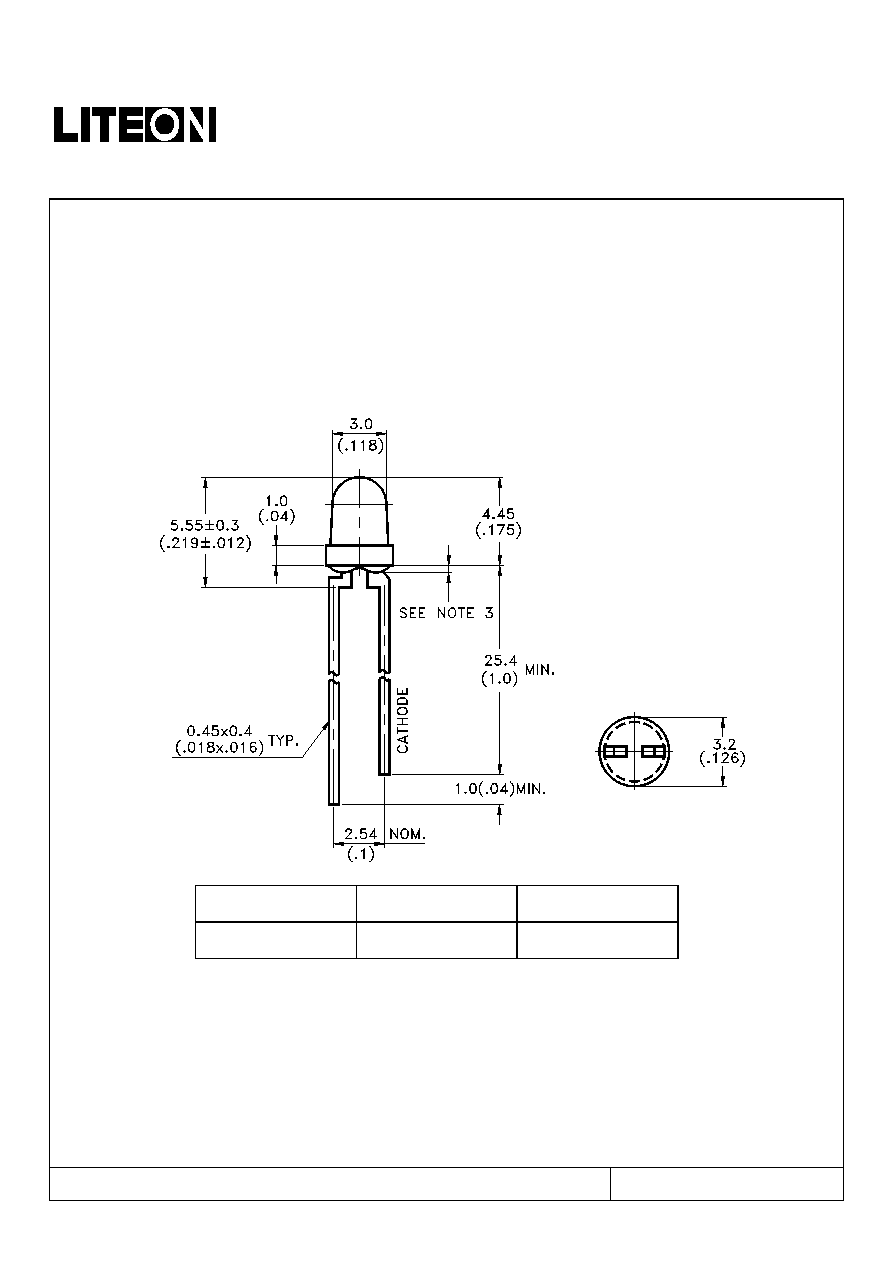
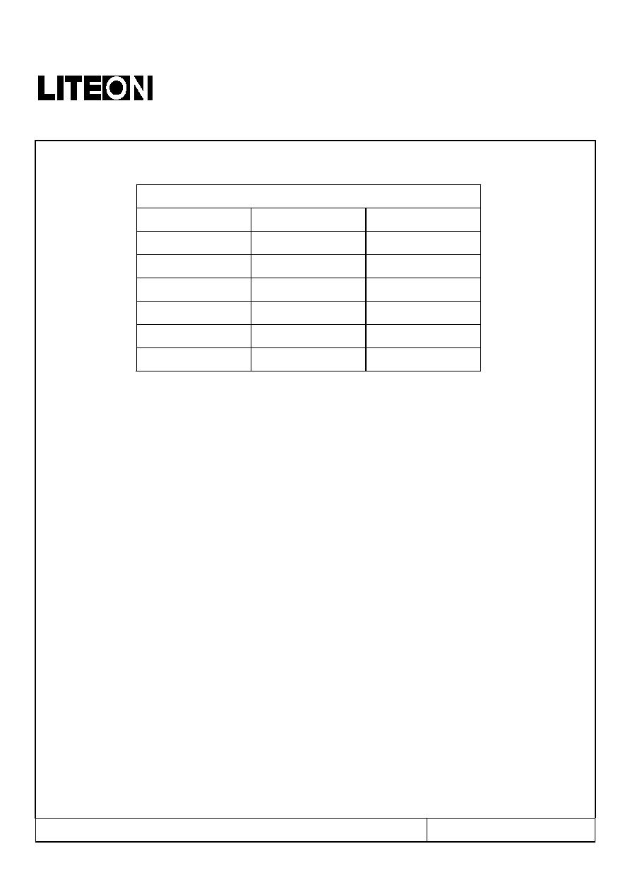
Package Dimensions
Part No.
Lens
Source Color
LTL42CB6N
Water Clear
InGaN Blue
Notes:
1. All dimensions are in millimeters (inches).
2. Tolerance is ±0.25mm(.010") unless otherwise noted.
3. Protruded resin under flange is 1.0mm(.04") max.
4. Lead spacing is measured where the leads emerge from the package.
5. Specifications are subject to change without notice.
Part No. : LTL42CB6N
Page : 1 of 10
BNS-OD-C131/A4
LITE-ON TECHNOLOGY CORPORATION
P r o p e r t y o f L i t e - O n O n l y
Absolute Maximum Ratings at T
A
=25
Parameter
Maximum
Rating
Unit
Power
Dissipation
120
mW
Peak Forward Current
(1/10 Duty Cycle, 0.1ms Pulse Width)
100 mA
DC Forward Current
30
mA
Derating Linear From 30 0.5
mA/
Reverse
Voltage
5
V
Operating Temperature Range
-20 to + 80
Storage Temperature Range
-30 to + 100
Lead Soldering Temperature
[1.6mm(.063") From Body]
260 for 5 Seconds
Part No. : LTL42CB6N
Page : 2 of 10
BNS-OD-C131/A4
LITE-ON TECHNOLOGY CORPORATION
P r o p e r t y o f L i t e - O n O n l y
Electrical / Optical Characteristics at T
A
=25
Parameter Symbol
Min.
Typ.
Max.
Unit
Test
Condition
Luminous Intensity
I
V
600 1900 mcd
I
F
= 20mA
Note 1,5
Viewing Angle
2
1/2
50
deg
Note 2 (Fig.6)
Peak Emission Wavelength
P
468 nm
Measurement
@Peak (Fig.1)
Dominant Wavelength
d
470 nm
Note 3
Spectral Line Half-Width
26
nm
Forward Voltage
V
F
3.5
4.0
V
I
F
= 20mA
Reverse Current
I
R
100
µA
V
R
= 5V
NOTE: 1. Luminous intensity is measured with a light sensor and filter combination that approximates the CIE
eye-response curve.
2.
1/2
is the off-axis angle at which the luminous intensity is half the axial luminous intensity.
3. The dominant wavelength, d is derived from the CIE chromaticity diagram and represents the single
wavelength which defines the color of the device.
4. Iv classification code is marked on each packing bag.
5. The Iv guarantee should be added ±15tolerance.
6. Precautions in handling:
∑
When soldering, leave 2mm of minimum clearance from the resin to the soldering point.
∑
Dipping the resin to solder must be avoided.
∑
Correcting the soldered position after soldering must be avoided.
∑
In soldering, do not apply any stress to the lead frame particularly when heated.
∑
When forming a lead, make sure not to apply any stress inside the resin.
∑
Lead forming must be done before soldering.
∑
It is necessary to cut the lead frame at normal temperature.
7. Caution in ESD:
Static Electricity and surge damages the LED. It is recommend to use a wrist band or anti-electrostatic
glove when handling the LED. All devices, equipment and machinery must be properly grounded.
Part No. : LTL42CB6N
Page : 3 of 10
BNS-OD-C131/A4

LITE-ON TECHNOLOGY CORPORATION
P r o p e r t y o f L i t e - O n O n l y
Typical Electrical / Optical Characteristics Curves
(25 Ambient Temperature Unless Otherwise Noted)
Part No. : LTL42CB6N
Page : 4 of 10
BNS-OD-C131/A4
LITE-ON TECHNOLOGY CORPORATION
P r o p e r t y o f L i t e - O n O n l y
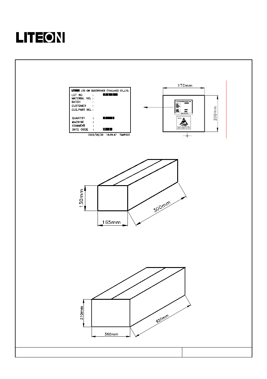
Packing Spec
1000, 500 or 250 pcs per packing bag
10 packing bags per inner carton
total 10000 pcs per inner carton
8 Inner cartons per outer carton
total 80000 pcs per outer carton
In every shipping lot, only the last pack will be non-full packing
Part No. : LTL42CB6N
Page : 5 of 10
BNS-OD-C131/A4
LITE-ON TECHNOLOGY CORPORATION
P r o p e r t y o f L i t e - O n O n l y
Bin Code List For Reference
Luminous Intensity Unit : mcd @20mA
Bin Code
Min.
Max.
R1 600 796
R2 796 1060
S1 1060 1420
S2 1420 1900
T1 1900 2540
T2 2540 3390
Note: Tolerance of each bin limit is ±15%
Part No. : LTL42CB6N
Page : 6 of 10
BNS-OD-C131/A4
LITE-ON TECHNOLOGY CORPORATION
P r o p e r t y o f L i t e - O n O n l y
CAUTIONS
1. Application
The LEDs described here are intended to be used for ordinary electronic equipment (such as office equipment,
communication equipment and household applications).Consult Liteon's Sales in advance for information on
applications in which exceptional reliability is required, particularly when the failure or malfunction of the
LEDs may directly jeopardize life or health (such as in aviation, transportation, traffic control equipment,
medical and life support systems and safety devices).
2. Storage
The storage ambient for the LEDs should not exceed 30∞C temperature or 70% relative humidity.
It is recommended that LEDs out of their original packaging are used within three months.
For extended storage out of their original packaging, it is recommended that the LEDs be stored in
a sealed container with appropriate desiccant or in desiccators with nitrogen ambient.
3. Cleaning
Use alcohol-based cleaning solvents such as isopropyl alcohol to clean the LEDs if necessary.
4. Lead Forming & Assembly
During lead forming, the leads should be bent at a point at least 3mm from the base of LED lens.
Do not use the base of the lead frame as a fulcrum during forming.
Lead forming must be done before soldering, at normal temperature.
During assembly on PCB, use minimum clinch force possible to avoid excessive mechanical stress.
5. Soldering
When soldering, leave a minimum of 2mm clearance from the base of the lens to the soldering point.
Dipping the lens into the solder must be avoided.
Do not apply any external stress to the lead frame during soldering while the LED is at high temperature.
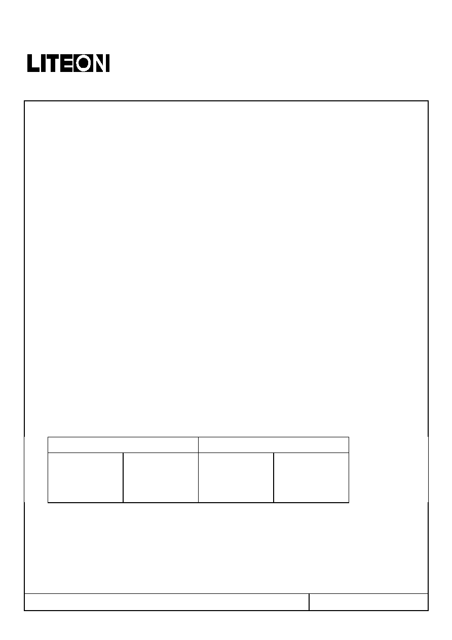
Recommended soldering conditions :
Soldering iron
Wave soldering
Temperature
Soldering time
300∞C Max.
3 sec. Max.
(one time only)
Pre-heat
Pre-heat time
Solder wave
Soldering time
100∞C Max.
60 sec. Max.
260∞C Max.
10 sec. Max.
Note: Excessive soldering temperature and/or time might result in deformation of the LED lens or
catastrophic failure of the LED
Part No. : LTL42CB6N
Page : 7 of 10
BNS-OD-C131/A4
LITE-ON TECHNOLOGY CORPORATION
P r o p e r t y o f L i t e - O n O n l y
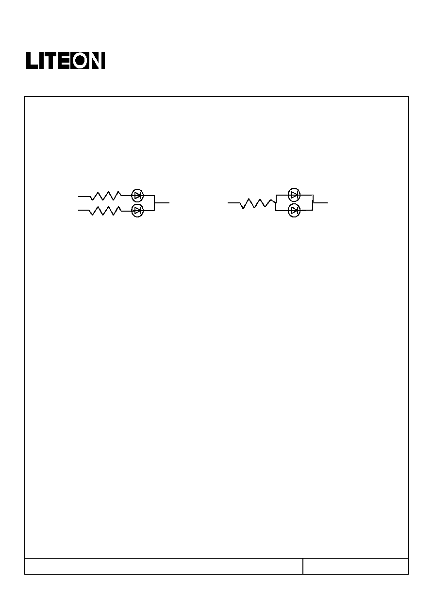
6. Drive Method
An LED is a current-operated device. In order to ensure intensity uniformity on multiple LEDs
connected in parallel in an application, it is recommended that a current limiting resistor be
incorporated in the drive circuit, in series with each LED as shown in Circuit A below.
Circuit model A Circuit model B
LED
LED
(A) Recommended circuit
(B) The brightness of each LED might appear different due to the differences in the I-V characteristics
of those LEDs
7. ESD (Electrostatic Discharge)
Static Electricity or power surge will damage the LED.
Suggestions to prevent ESD damage:
Use a conductive wrist band or anti- electrostatic glove when handling these LEDs
All devices, equipment, and machinery must be properly grounded
Work tables, storage racks, etc. should be properly grounded
Use ion blower to neutralize the static charge which might have built up on surface of the LEDs
plastic lens as a result of friction between LEDs during storage and handing
Part No. : LTL42CB6N
Page : 8 of 10
BNS-OD-C131/A4
LITE-ON TECHNOLOGY CORPORATION
P r o p e r t y o f L i t e - O n O n l y
Suggested checking list :
Training and Certification
1. Everyone working in a static-safe area is ESD-certified?
2. Training records kept and re-certification dates monitored?
Static-Safe Workstation & Work Areas
1. Static-safe workstation or work-areas have ESD signs?
2. All surfaces and objects at all static-safe workstation and within 1 ft measure less than 100V?
3. All ionizer activated, positioned towards the units?
4. Each work surface mats grounding is good?
Personnel Grounding
1. Every person (including visitors) handling ESD sensitive (ESDS) items wear wrist strap, heel strap or
conductive shoes with conductive flooring?
2. If conductive footwear used, conductive flooring also present where operator stand or walk?
3. Garments, hairs or anything closer than 1 ft to ESD items measure less than 100V*?
4. Every wrist strap or heel strap/conductive shoes checked daily and result recorded for all DSL?
5. All wrist strap or heel strap checkers calibration up to date?
Note: *50V for Blue LED.
Device Handling
1. Every ESDS items identified by EIA-471 labels on item or packaging?
2. All ESDS items completely inside properly closed static-shielding containers when not at static-safe
workstation?
3. No static charge generators (e.g. plastics) inside shielding containers with ESDS items?
4. All flexible conductive and dissipative package materials inspected before reuse or recycle?
Others
1. Audit result reported to entity ESD control coordinator?
2. Corrective action from previous audits completed?
3. Are audit records complete and on file?
Part No. : LTL42CB6N
Page : 9 of 10
BNS-OD-C131/A4
LITE-ON TECHNOLOGY CORPORATION
P r o p e r t y o f L i t e - O n O n l y
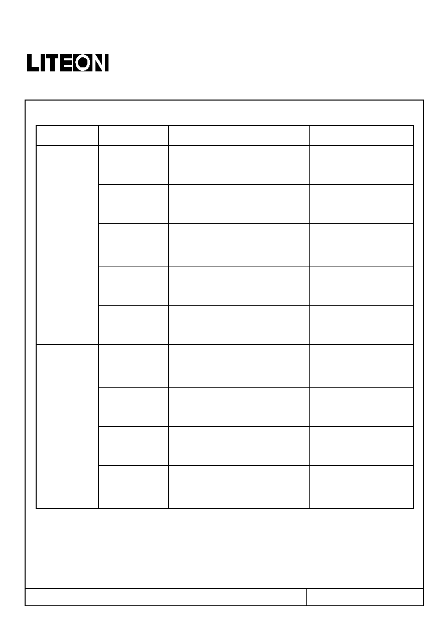
8. Reliability Test
Classification
Test Item
Test Condition
Reference Standard
Operation Life
Ta= Under Room Temperature As
Per Data Sheet Maximum Rating
*Test Time= 1000HRS (-24HRS,+72HRS)
MIL-STD-750D:1026 (1995)
MIL-STD-883D:1005 (1991)
JIS C 7021:B-1 (1982)
High Temperature
High Humidity
Storage
Ta= 65±5
RH= 90 95%
Test Time= 240HRS±2HRS
MIL-STD-202F: 103B(1980)
JIS C 7021 : B-11(1982)
High Temperature
High Humidity
Reverse BIAS
Ta= 65±5
RH= 90 95%
VR=5V
Test Time = 500HRS (-24HRS, +48HRS)
JIS C 7021 : B-11(1982)
High Temperature
Storage
Ta= 105±5
*Test Time= 1000HRS (-24HRS,+72HRS)
MIL-STD-883D:1008 (1991)
JIS C 7021:B-10 (1982)
Endurance
Test
Low Temperature
Storage
Ta= -55±5
*Test Time=1000HRS (-24HRS,+72HRS)
JIS C 7021:B-12 (1982)
Temperature
Cycling
105
25
-55
25
30mins 5mins 30mins 5mins
10 Cycles
MIL-STD-202F:107D (1980)
MIL-STD-750D:1051(1995)
MIL-STD-883D:1010 (1991)
JIS C 7021: A-4(1982)
Thermal
Shock
105 ± 5
-55 ± 5
10mins 10mins
10 Cycles
MIL-STD-202F:107D(1980)
MIL-STD-750D:1051(1995)
MIL-STD-883D:1011 (1991)
Solder
Resistance
T.sol = 260 ± 5
Dwell Time= 10 ± 1secs
MIL-STD-202F:210A(1980)
MIL-STD-750D:2031(1995)
JIS C 7021: A-1(1982)
Environmental
Test
Solderability
T. sol = 230 ± 5
Dwell Time= 5 ± 1secs
MIL-STD-202F:208D(1980)
MIL-STD-750D:2026(1995)
MIL-STD-883D:2003(1991)
JIS C 7021: A-2(1982)
9. Others
The appearance and specifications of the product may be modified for improvement, without prior notice.
Part No. : LTL42CB6N
Page : 10 of 10
BNS-OD-C131/A4