LITE-ON TECHNOLOGY CORPORATION
P r o p e r t y o f L i t e - O n O n l y
Features
* Meet ROHS, Green Product.
* Reverse mount Chip LED.
* Ultra bright AlInGaP Chip LED.
* Package in 8mm tape on 7" diameter reels.
* Compatible with automatic placement equipment.
* Compatible with infrared and vapor phase reflow solder process.
* EIA STD package.
* I.C. compatible.
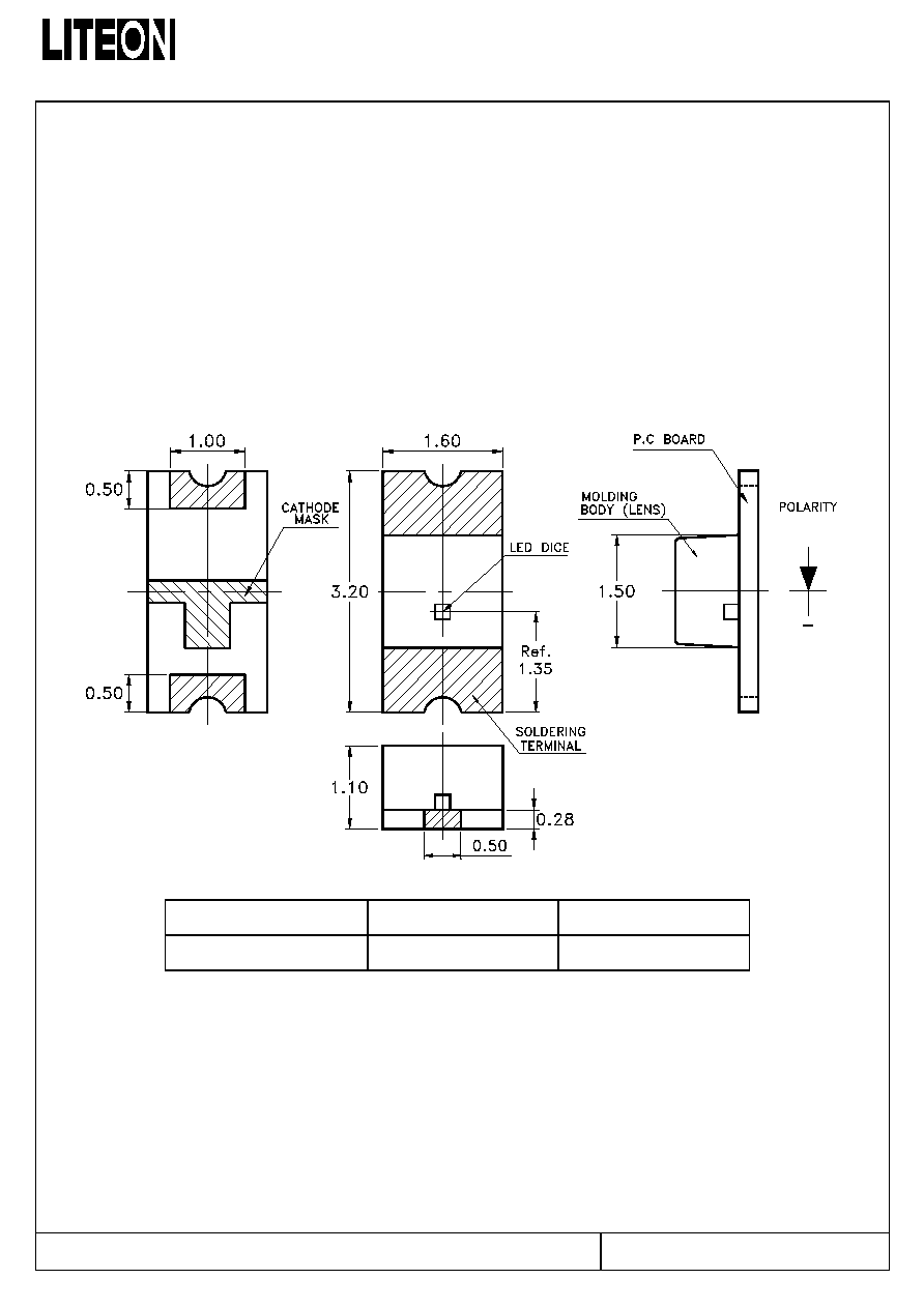
Package Dimensions
+
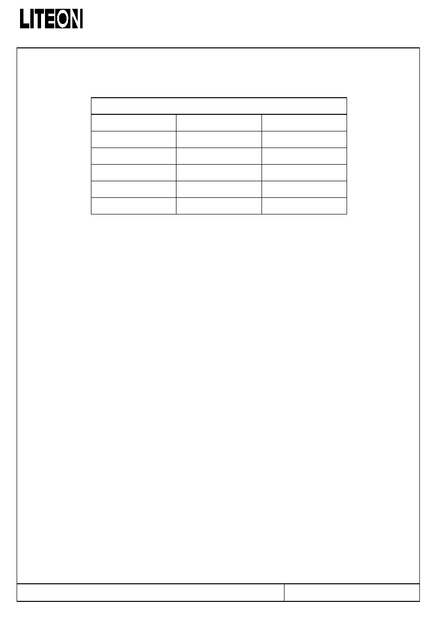
Part No.
Lens
Source Color
LTST-C230KSKT
Water Clear
AllnGaP Yellow
Notes:
1. All dimensions are in millimeters (inches).
2. Tolerance is ± 0.10 mm (.004") unless otherwise noted.
Part No. : LTST-C230KSKT
Page : 1 of 11
BNS-OD-C131/A4
LITE-ON TECHNOLOGY CORPORATION
P r o p e r t y o f L i t e - O n O n l y
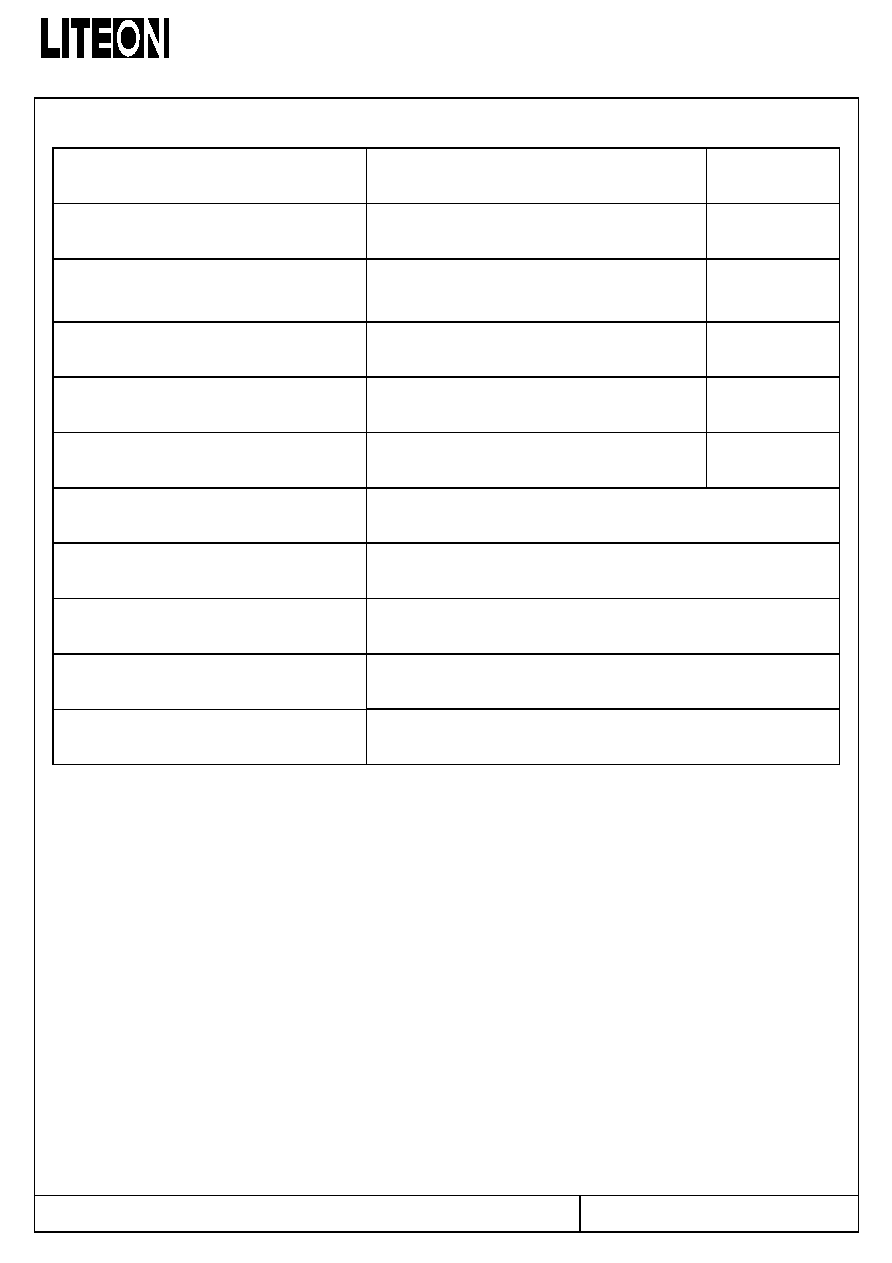
Absolute Maximum Ratings At Ta=25
Parameter LTST-C230KSKT
Unit
Power Dissipation
75
mW
Peak Forward Current
(1/10 Duty Cycle, 0.1ms Pulse Width)
80
mA
DC Forward Current
30
mA
Derating Linear From 50
∞
C
0.4
mA/
∞
C
Reverse Voltage
5
V
Operating Temperature Range
-55
∞
C to + 85
∞
C
Storage Temperature Range
-55
∞
C to + 85
∞
C
Wave Soldering Condition
260
∞
C For 5 Seconds
Infrared Soldering Condition
260
∞
C For 5 Seconds
Vapor Phase Soldering Condition
215
∞
C For 3 Minutes
Part No. : LTST-C230KSKT
Page : 2 of 11
BNS-OD-C131/A4
LITE-ON TECHNOLOGY CORPORATION
P r o p e r t y o f L i t e - O n O n l y
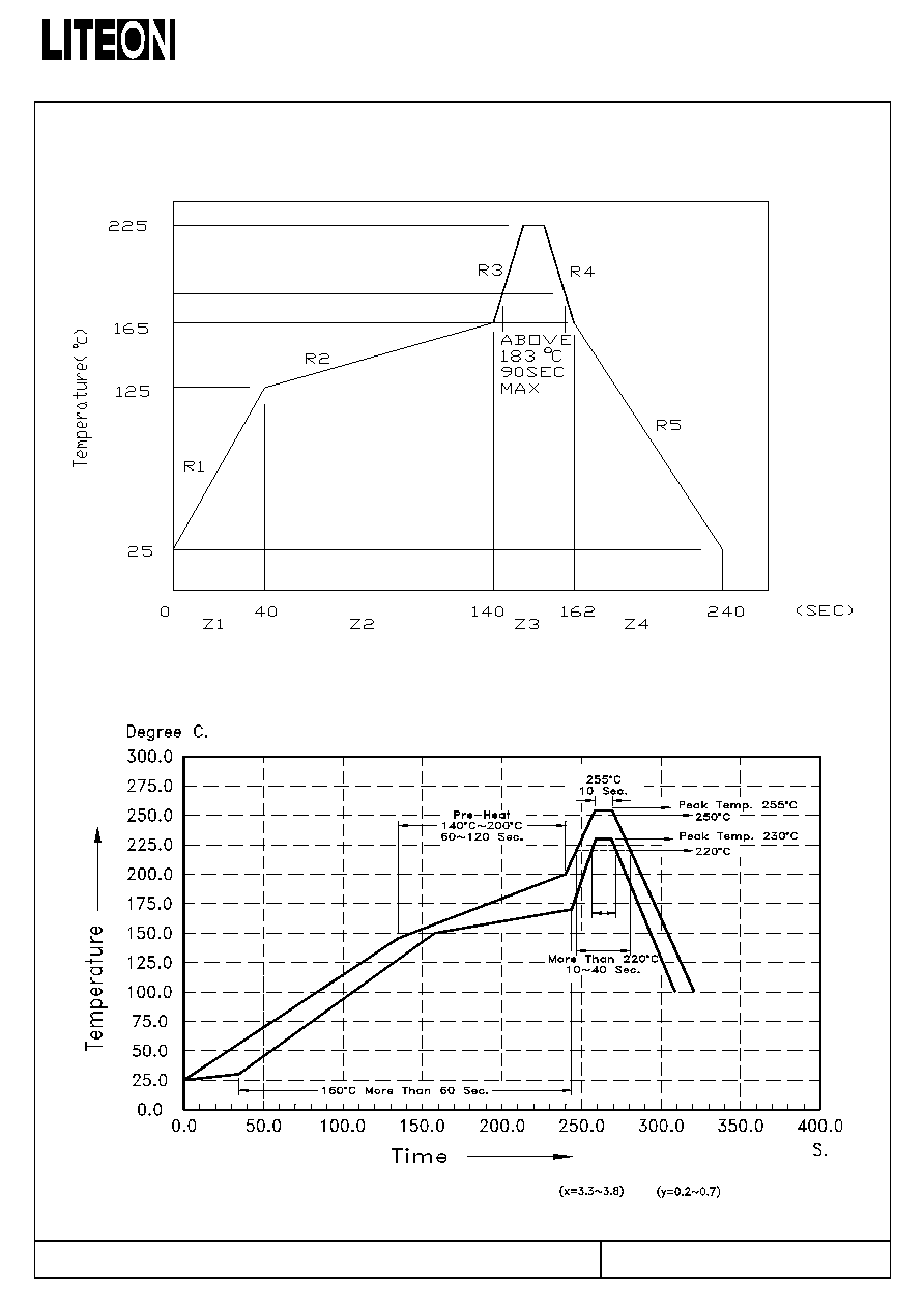
Suggestion Profile:
(1) Suggestion IR Reflow Profile For Normal Process
(2) Suggestion IR Reflow Profile For Pb Free Process
R e c o m m e n d e d P ro file B e tw e e n A s s e m b le A n d H e a t-R e sista n c e L in e
T h e P ro file is a v a ila b le th a t m u s t to u se S n A g C u s o ld e r p a ste
Part No. : LTST-C230KSKT
Page : 3 of 11
BNS-OD-C131/A4
LITE-ON TECHNOLOGY CORPORATION
P r o p e r t y o f L i t e - O n O n l y
Electrical Optical Characteristics At Ta=25
Parameter Symbol
Part No.
LTST-
Min. Typ. Max. Unit Test
Condition
Luminous Intensity
IV
C230KSKT
18.0
60.0
mcd
IF = 20mA
Note 1
Viewing Angle
21/2
C230KSKT
130
deg
Note 2 (Fig.6)
Peak Emission Wavelength
P
C230KSKT
588 nm
Measurement
@Peak (Fig.1)
Dominant Wavelength
d
C230KSKT
587 nm Note
3
Spectral Line Half-Width
C230KSKT
15 nm
Forward Voltage
VF
C230KSKT
2.0
2.4
V
IF = 20mA
Reverse Current
IR
C230KSKT
10
A
VR = 5V
Capacitance C
C230KSKT
40
PF
VF = 0
f = 1MHZ
Notes: 1. Luminous intensity is measured with a light sensor and filter combination that approximates the
CIE eye-response curve.
2. 1/2 is the off-axis angle at which the luminous intensity is half the axial luminous intensity.
3. The dominant wavelength, d is derived from the CIE chromaticity diagram and represents the
single wavelength which defines the color of the device.
Part No. : LTST-C230KSKT
Page : 4 of 11
BNS-OD-C131/A4
LITE-ON TECHNOLOGY CORPORATION
P r o p e r t y o f L i t e - O n O n l y
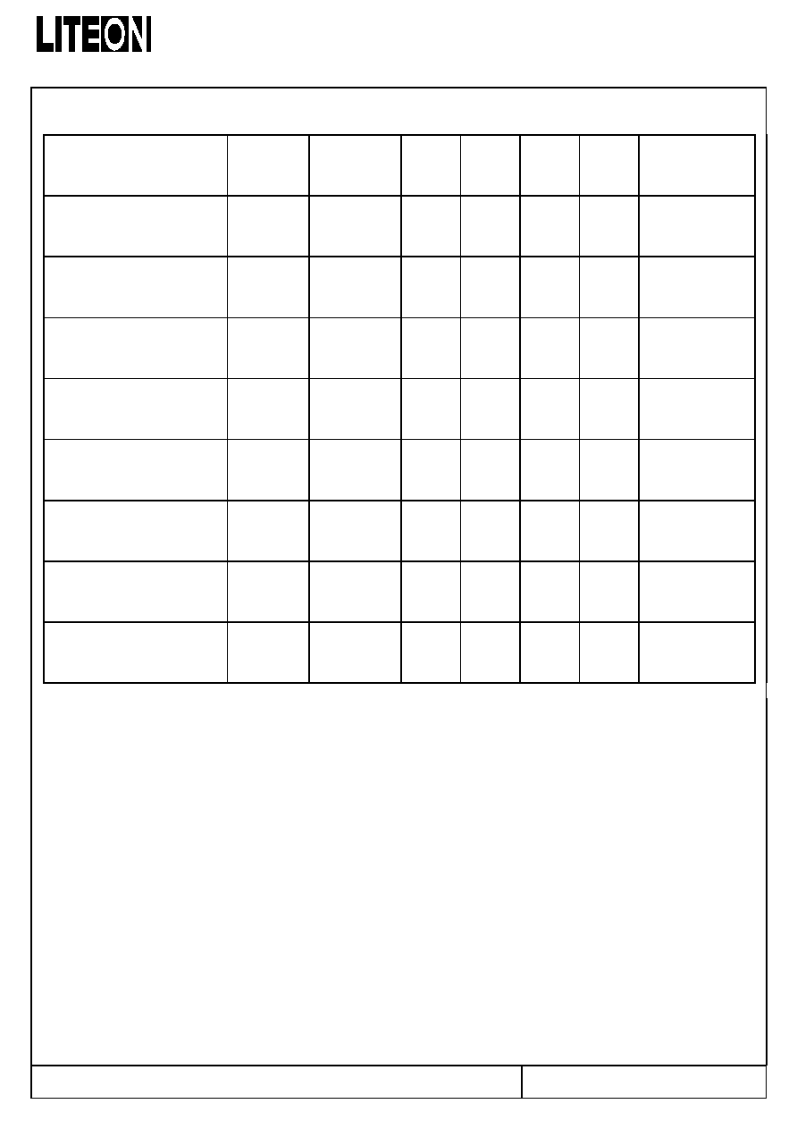
Bin Code List
Part No. : LTST-C230KSKT
Page : 5 of 11
BNS-OD-C131/A4
Luminous Intensity Unit : mcd @20mA
Bin Code
Min.
Max.
M 18.0 28.0
N 28.0 45.0
P 45.0
71.0
Q 71.0
112.0
R 112.0
180.0
Tolerance on each Intensity bin is +/-15%