U.L. RECOGNIZED
File #E71639
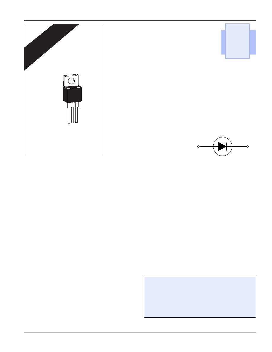
TO-220
Isolated
A
C
©2004 Littelfuse, Inc.
E7 - 1
http://www.littelfuse.com
Thyristor Product Catalog
+ 1 972-580-7777
Rectifiers
(15 A to 25 A)
E7
General Description
Teccor manufactures 15 A rms to 25 A rms rectifiers with volt-
ages rated from 200 V to 1000 V. Due to the electrically-isolated
TO-220 package, these rectifiers may be used in common anode
or common cathode circuits using only one part type, thereby
simplifying stock requirements.
Teccor's silicon rectifiers feature glass-passivated junctions to
ensure long term reliability and stability. In addition, glass offers
a rugged, reliable barrier against junction contamination.
Features
∑
Electrically-isolated packages
∑
High voltage capabilities -- 200 V to 1000 V
∑
High surge capabilities -- up to 350 A
∑
Glass-passivated junctions
E7

http://www.littelfuse.com
E7 - 2
©2004 Littelfuse, Inc.
+ 1 972-580-7777
Thyristor Product Catalog
Rectifiers
Data Sheets
Test Conditions
I
2
t -- RMS surge (non-repetitive) forward current for 8.3 ms for fusing
I
F(AV)
-- Average forward current
I
F(RMS)
-- RMS forward current
I
FSM
-- Peak one-cycle surge current
I
RM
-- Peak reverse current
R
JC
-- Thermal resistance (steady state) junction to case
V
FM
-- Peak forward voltage at rated average forward current
V
R
-- DC blocking voltage
V
RRM
-- Peak repetitive reverse voltage
General Notes
∑
Operating temperature range (T
J
) is -40
∞C to +125 ∞C.
∑
Storage temperature range (T
S
) is -40
∞C to +125 ∞C.
∑
Lead solder temperature is a maximum of 230
∞C for 10 seconds
maximum at a minimum of 1/16" (1.59 mm) from case.
∑
The case temperature (T
C
) is measured as shown on dimensional
outline drawings in the "Package Dimensions" section of this
catalog.
∑
Teccor's electrically-isolated TO-220 devices withstand a high
potential test of 2500 V ac rms from leads to mounting tab over the
operating temperature range.
∑
Typical Reverse Recovery Time (t
rr
) is 4 µs. (Test conditions =
0.9 A forward current and 1.5 A reverse current.)
Electrical Specification Notes
(1) See Figure E7.3 for current rating at specified case temperature.
(2) For more than one full cycle rating, see Figure E7.4.
(3) T
C
= T
J
for test conditions
(4) See package outlines for lead form configurations. When ordering
special lead forming, add type number as suffix to part number.
Electrical Isolation
* UL Recognized File #E71639
** For 4000 V isolation, use "V" suffix in the part number.
Type
Part Number
V
RRM
V
R
I
F(AV)
I
F(RMS)
I
FSM
I
RM
V
FM
I
2
t
R
JC
Isolated
TO-220
Volts
Volts
(1)
Amps
Amps
(2)
Amps
(3)
mA
Volts
Amps
2
Sec
∞C/W
60/50 Hz
T
C
=
25
∞C
T
C
=
100
∞C
T
C
=
125
∞C
T
C
=25
∞C
See "Package Dimensions"
section for variations. (4)
MIN
MIN
MAX
MAX
MAX
MAX
TYP
15 A
D2015L
200
200
9.5
15
225/188
0.1
0.5
1
1.6
210
2.85
D4015L
400
400
9.5
15
225/188
0.1
0.5
1
1.6
210
2.85
D6015L
600
600
9.5
15
225/188
0.1
0.5
1
1.6
210
2.85
D8015L
800
800
9.5
15
225/188
0.1
0.5
1
1.6
210
2.85
DK015L
1000
1000
9.5
15
225/188
0.1
3
1.6
210
2.85
20 A
D2020L
200
200
12.7
20
300/255
0.1
0.5
1
1.6
374
2.5
D4020L
400
400
12.7
20
300/255
0.1
0.5
1
1.6
374
2.5
D6020L
600
600
12.7
20
300/255
0.1
0.5
1
1.6
374
2.5
D8020L
800
800
12.7
20
300/255
0.1
0.5
1
1.6
374
2.5
DK020L
1000
1000
12.7
20
300/255
0.1
3
1.6
374
2.5
25 A
D2025L
200
200
15.9
25
350/300
0.1
0.5
1
1.6
508
2.7
D4025L
400
400
15.9
25
350/300
0.1
0.5
1
1.6
508
2.7
D6025L
600
600
15.9
25
350/300
0.1
0.5
1
1.6
508
2.7
D8025L
800
800
15.9
25
350/300
0.1
0.5
1
1.6
508
2.7
DK025L
1000
1000
15.9
25
350/300
0.1
3
1.6
508
2.7
C
A
Not
Used
Electrical Isolation
from Leads to Mounting Tab *
V AC RMS
TO-220
Isolated
2500
Standard
4000
Optional **

©2004 Littelfuse, Inc.
E7 - 3
http://www.littelfuse.com
Thyristor Product Catalog
+1 972-580-7777
Data Sheets
Rectifiers
Figure E7.1 Instantaneous Forward Current versus Forward Voltage
(Typical)
Figure E7.2 Forward Power Dissipation (Typical)
Figure E7.3 Maximum Allowable Case Temperature versus
Average Forward Current
Figure E7.4 Peak Surge Forward Current versus Surge Current
Duration
0
0.6
0.8
1.0
1.2
1.4
1.6
1.8
0
20
40
60
80
100
120
140
Instantaneous Forward Voltage (v
F
) ≠ Volts
Instantaneous Forward Current (
i
F
) ≠ Amps
15 A Devices
T
C
= 25∞C
20 A Devices
25 A Devices
16
12
0
2
4
6
8
10
12
14
0
4
8
12
16
20
SINGLE PULSE RECTIFICATION
60 Hz SINE WAVE
20 A Devices
15 A Devices
25 A Devices
Average Forward Current [I
F(AV)
] ≠ Amps
Average
Forward
Power D
issipation
[P
F(AV)
] ≠ Watts
0
2
4
6
8
10
12
14
0
70
75
80
85
90
95
100
105
110
115
120
125
20 A Devices
15 A Devices
Average Forward Current [I
F (AV)
] ≠ Amps
Maximum Allowable Case Temperature (T
C
) ≠ ∞C
SUPPLY FREQUENCY: 60 Hz Sine Wave
LOAD: Resistive or Inductive
CASE TEMPERATURE:
Measured As Shown on Dimensional Drawing
16
25 A Devices
10
20
30
40
60
80
100
200
300
400
600
800
1000
1
2
4
6
10
20
40
60
100
200
400
600
1000
Surge Current Duration ≠ Cycles
SUPPLY FREQUENCY: 60 Hz Sinewave
LOAD: Resistive or Inductive
RMS ON-STATE CURRENT: [I
F(RMS)
]
Maximium Rated Value at Specified
Case Temperature
15 A Devices
20 A Devices
25 A Devices
Peak Surge (Non-repetitive)
Forward Current (I
FSM
) ≠ Amps