 | –≠–ª–µ–∫—Ç—Ä–æ–Ω–Ω—ã–π –∫–æ–º–ø–æ–Ω–µ–Ω—Ç: P6KE27 | –°–∫–∞—á–∞—Ç—å:  PDF PDF  ZIP ZIP |
285
w w w . l i t t e l f u s e . c o m
6
SILICON DIODE
ARRA
YS
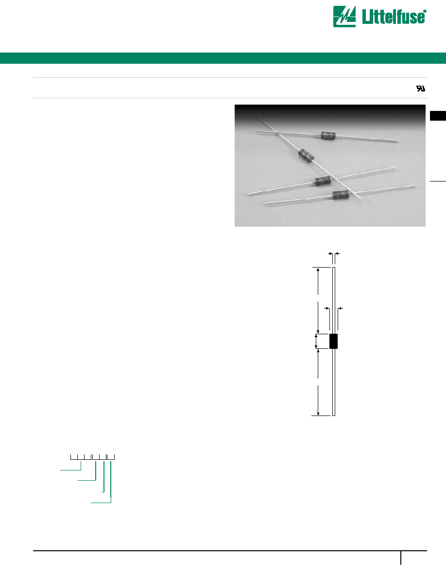
Silicon Avalanche Diodes
600 Watt Axial Transient Voltage Suppressors
Protect sensitive electronics against voltage transients induced by
inductive load switching and lightning. Ideal for the protection
of I/O interfaces, Vcc bus, and other integrated circuits.
FEATURES
∑
Breakdown voltage range 6.8 to 440 Volts
∑
Uni-directional and Bi-directional
∑
Glass passivated junction
∑
Excellent clamping capability
∑
100% surge tested
∑
UL recognised
MAXIMUM RATING
∑
Peak Pulse Power (Ppk): 600 Watts (10 x 1000µs)@25∞C
(see diagram on page 3 for wave form)
∑
1.5 watt steady state
∑
Response time: 1 x 10
-12
seconds (theoretical)
∑
Forward surge rating: 100 Amps, 8.3ms half sine wave, (uni-
directional devices only)
∑
Operating & storage temperature: -55∞C to +150∞C
MECHANICAL CHARACTERISTICS
∑
Case: DO-15, Molded plastic over glass passivated junction
∑
Terminals: Axial leads, solderable per MIL-STD-202"
Method 208
∑
Solderable leads = 230∞C for 10 seconds (1.59mm from case)
∑
Marking: cathode band, (positive terminal, uni-directional
devices only),
device code, logo
∑
Weight: 1.2 grammes (approx)
Agency Approvals:
Recognized under the Components
Program of Underwriters Laboratories.
Agnecy File Number:
E128662
0.76
0.86
3.05
3.25
Min 25.4
6.10
6.47
Min 25.4
P6KE
C A
Voltage
Bi-Directional
5% Voltage Tolerance
Packaging Option
B = Bulk (1000 pcs)
T = Tape and reeled (5000 pcs)
ORDERING INFORMATION
P6KE Series
All dimensions in mm
Æ
Silicon Avalanche Diodes
286
w w w . l i t t e l f u s e . c o m
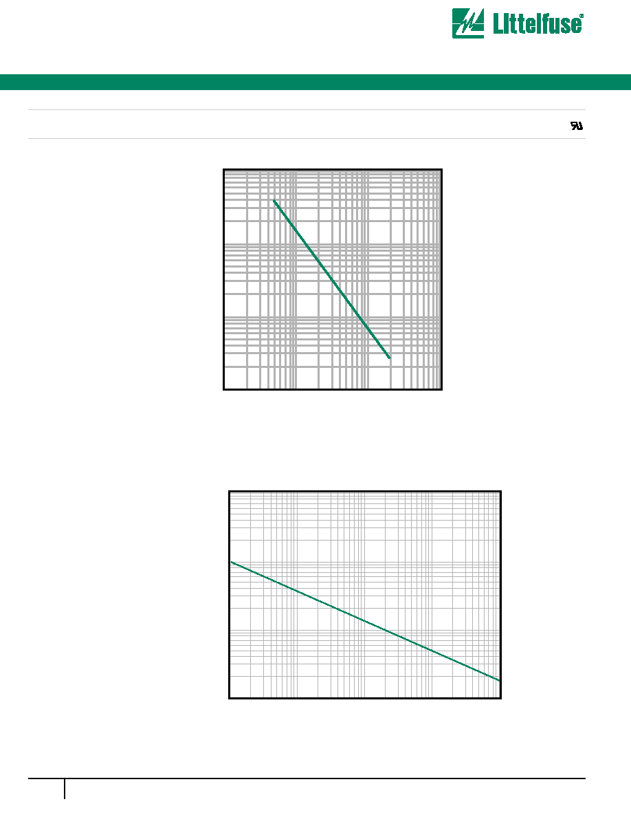
Device Stand-off Voltage - Volts
1
10
100
1000
10000
1000
Cj (pf)
100
10
Pulse Time (tp)
1
µs
10
µs
100
µs
1ms
10ms
100w
500w
Pp
(kw)
2kw
5kw
20kw
100kw
Figure 1 - Capacitance vs. Stand-off Voltage
Figure 2 - Peak Pulse Power vs. Pulse Time
600 Watt Axial Transient Voltage Suppressors
P6KE Series
Æ
287
w w w . l i t t e l f u s e . c o m
6
SILICON DIODE
ARRA
YS
PP6KE6.8*
P6KE6.8A*
P6KE7.5*
P6KE7.5A*
P6KE8.2
P6KE8.2A
P6KE9.1
P6KE9.1A
P6KE10
P6KE10A
P6KE11
P6KE11A
P6KE12*
P6KE12A*
P6KE13
P6KE13A
P6KE15
P6KE15A
P6KE16
P6KE16A
P6KE18*
P6KE18A*
P6KE20
P6KE20A
P6KE22
P6KE22A
P6KE24
P6KE24A
P6KE27*
P6KE27A*
P6KE30*
P6KE30A*
Part
Number
(Uni)
Part
Number
(Bi)
PP6KE6.8C*
P6KE6.8CA*
P6KE7.5C*
P6KE7.5CA*
P6KE8.2C
P6KE8.2CA
P6KE9.1C
P6KE9.1CA
P6KE10C
P6KE10CA
P6KE11C
P6KE11CA
P6KE12C*
P6KE12CA*
P6KE13C
P6KE13CA
P6KE15C*
P6KE15CA*
P6KE16C
P6KE16CA
P6KE18C*
P6KE18CA*
P6KE20C*
P6KE20CA*
P6KE22C
P6KE22CA
P6KE24C
P6KE24CA
P6KE27C
P6KE27CA
P6KE30C*
P6KE30CA*
Reverse
Stand off
Voltage
V
R
(Volts)
5.50
5.80
6.05
6.40
6.63
7.02
7.37
7.78
8.10
8.55
8.92
9.40
9.72
10.20
10.50
11.10
12.10
12.80
12.90
13.60
14.50
15.30
16.20
17.10
17.80
18.80
19.40
20.50
21.80
23.10
24.30
25.60
Breakdown
Voltage
V
BR
(Volts) @
I
T
MIN
6.12
6.45
6.75
7.13
7.38
7.79
8.19
8.65
9.00
9.50
9.90
10.50
10.80
11.40
11.70
12.40
13.50
14.30
14.40
15.20
16.20
17.10
18.00
19.00
19.80
20.90
21.60
22.80
0
24.30
25.70
27.00
28.50
MAX
7.48
7.14
8.25
7.88
9.02
8.61
10.00
9.55
11.00
10.50
12.10
11.60
13.20
12.60
14.30
13.70
16.50
15.80
17.60
16.80
19.80
18.90
22.00
21.00
24.20
23.10
26.40
25.20
29.70
28.40
33.00
31.50
(mA)
10.0
10.0
10.0
10.0
10.0
10.0
1.0
1.0
1.0
1.0
1.0
1.0
1.0
1.0
1.0
1.0
1.0
1.0
1.0
1.0
1.0
1.0
1.0
1.0
1.0
1.0
1.0
1.0
1.0
1.0
1.0
1.0
Maximum
Reverse
Leakage
I
R
@ V
R
(µA)
1000.0
1000.0
500.0
500.0
200.0
200.0
50.0
50.0
10.0
10.0
5.0
5.0
5.0
5.0
5.0
5.0
5.0
5.0
5.0
5.0
5.0
5.0
5.0
5.0
5.0
5.0
5.0
5.0
5.0
5.0
5.0
5.0
Maximum
Clamping
Voltage
V
C
@
I
PP
(Volts)
10.8
10.5
11.7
11.3
12.5
12.1
13.8
13.4
15.0
14.5
16.2
15.6
17.3
16.7
19.0
18.2
22.0
21.2
23.5
22.5
26.5
25.2
29.1
27.7
31.9
30.6
34.7
33.2
39.1
37.5
43.5
41.4
Maximum
Peak Pulse
Current
I
PP
(A)
56.0
57.0
51.0
53.0
48.0
50.0
44.0
45.0
40.0
41.0
37.0
38.0
35.0
36.0
32.0
33.0
27.0
28.0
26.0
27.0
23.0
24.0
21.0
22.0
19.0
20.0
17.0
18.0
15.0
16.0
14.0
14.4
Suffix `C' denotes Bi-directional device. Suffix `A' denotes 5% tolerance device, no suffix denotes a 10% tolerance device.
1.
For Bi-directional devices having V
R
of 10 volts and below, the I
R
limit is doubled.
2.
V
F
= 3.5 Volts max. for devices of V
R
<100v, and V
F
= 5.0 Volts max for devices of V
R
>100V. I
F
=
50A, 300 µS square wave.
* Preferred voltages.
Max
Voltage
Temperature
Variation
of V
BR
(mV/∞C)
0.057
0.057
0.061
0.061
0.065
0.065
0.068
0.068
0.073
0.073
0.075
0.075
0.078
0.078
0.081
0.081
0.084
0.084
0.086
0.086
0.088
0.088
0.090
0.090
0.092
0.092
0.094
0.094
0.096
0.096
0.097
0.097
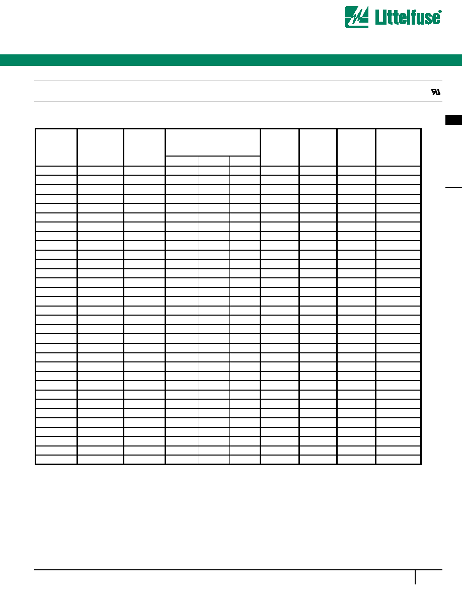
P6KE Series
ELECTRICAL SPECIFICATION @ Tamb 25∞C
Silicon Avalanche Diodes
600 Watt Axial Transient Voltage Suppressors
Æ

Silicon Avalanche Diodes
288
w w w . l i t t e l f u s e . c o m
Part
Number
(Uni)
Part
Number
(Bi)
Reverse
Stand off
Voltage
V
R
(Volts)
Breakdown
Voltage
V
BR
(Volts) @ I
T
Maximum
Reverse
Leakage
I
R
@ V
R
(µA)
Maximum
Clamping
Voltage
V
C
@
I
PP
(Volts)
Maximum
Peak Pulse
Current
I
PP
(A)
Suffix `C' denotes Bi-directional device. Suffix `A' denotes 5% tolerance device, no suffix denotes a 10% tolerance device.
1.
For Bi-directional devices having V
R
of 10 volts and below, the I
R
limit is doubled.
2.
V
F
= 3.5 Volts max. for devices of V
R
<100v, and V
F
= 5.0 Volts max for devices of V
R
>100V. I
F
=
50A, 300 µS square wave.
* Preferred voltages.
Max
Voltage
Temperature
Variation
of V
BR
(mV/∞C)
P6KE Series
ELECTRICAL SPECIFICATION @ Tamb 25∞C
P6KE33*
P6KE33A*
P6KE36*
P6KE36A*
P6KE39
P6KE39A
P6KE43
P6KE43A
P6KE47
P6KE47A
P6KE51
P6KE51A
P6KE56
P6KE56A
P6KE62
P6KE62A
P6KE68
P6KE68A
P6KE75
P6KE75A
P6KE82
P6KE82A
P6KE91
P6KE91A
P6KE100
P6KE100A
P6KE110
P6KE110A
P6KE120
P6KE120A
P6KE130
P6KE130A
P6KE150
P6KE150A
P6KE160
P6KE160A
P6KE33C
P6KE33CA
P6KE36C
P6KE36CA
P6KE39C
P6KE39CA
P6KE43C
P6KE43CA
P6KE47C
P6KE47CA
P6KE51C*
P6KE51CA*
P6KE56C
P6KE56CA
P6KE62C
P6KE62CA
P6KE68C*
P6KE68CA*
P6KE75C
P6KE75CA
P6KE82C
P6KE82CA
P6KE91C
P6KE91CA
P6KE100C
P6KE100CA
P6KE110C
P6KE110CA
P6KE120C
P6KE120CA
P6KE130C
P6KE130CA
P6KE150C
P6KE150CA
P6KE160C
P6KE160CA
26.80
28.20
29.10
30.80
31.60
33.30
34.80
36.80
38.10
40.20
41.30
43.60
45.4
47.8
50.2
53.0
55.1
58.1
60.7
64.1
66.4
70.1
73.7
77.8
81.0
85.5
89.2
94.0
97.2
102.0
105.0
111.0
121.0
128.0
130.0
136.0
MIN
29.70
31.40
32.40
34.20
35.10
37.10
38.70
40.90
42.30
44.70
45.90
48.50
50.4
53.2
55.8
58.9
61.2
64.6
67.5
71.3
73.8
77.9
81.9
86.5
90.0
95.0
99.0
105.0
108.0
114.0
117.0
124.0
135.0
143.0
144.0
152.0
MAX
36.30
34.70
39.60
37.80
42.90
41.00
47.30
45.20
51.70
49.40
56.10
53.60
61.6
58.8
68.2
65.1
74.8
71.4
82.5
78.8
90.2
86.1
100.0
95.5
110.0
105.0
121.0
116.0
132.0
126.0
143.0
137.0
165.0
158.0
176.0
168.0
(mA
1.0
1.0
1.0
1.0
1.0
1.0
1.0
1.0
1.0
1.0
1.0
1.0
1.0
1.0
1.0
1.0
1.0
1.0
1.0
1.0
1.0
1.0
1.0
1.0
1.0
1.0
1.0
1.0
1.0
1.0
1.0
1.0
1.0
1.0
1.0
1.0
5.0
5.0
5.0
5.0
5.0
5.0
5.0
5.0
5.0
5.0
5.0
5.0
5.0
5.0
5.0
5.0
5.0
5.0
5.0
5.0
5.0
5.0
5.0
5.0
5.0
5.0
5.0
5.0
5.0
5.0
5.0
5.0
5.0
5.0
5.0
5.0
47.7
45.7
52.0
49.9
56.4
53.9
61.9
59.3
67.8
64.8
73.5
70.1
80.5
77.0
89.0
85.0
98.0
92.0
108.0
103.0
118.0
113.0
131.0
125.0
144.0
137.0
158.0
152.0
173.0
165.0
187.0
179.0
215.0
207.0
230.0
219.0
12.6
13.2
11.6
12.0
10.5
11.2
9.6
10.1
8.9
9.3
8.2
8.6
7.40
7.80
6.80
7.10
6.10
6.50
5.50
5.80
5.10
5.30
4.50
4.80
4.20
4.40
3.80
4.00
3.50
3.60
3.20
3.30
2.80
2.90
2.60
2.70
0.098
0.098
0.099
0.099
0.100
0.100
0.101
0.101
0.101
0.101
0.102
0.102
0.103
0.103
0.104
0.104
0.104
0.104
0.105
0.105
0.105
0.105
0.106
0.106
0.106
0.106
0.107
0.107
0.107
0.107
0.107
0.107
0.108
0.108
0.108
0.108
600 Watt Axial Transient Voltage Suppressors
Æ

289
w w w . l i t t e l f u s e . c o m
6
SILICON DIODE
ARRA
YS
Silicon Avalanche Diodes
Part
Number
(Uni)
Part
Number
(Bi)
Reverse
Stand off
Voltage
V
R
(Volts)
Breakdown
Voltage
V
BR
(Volts) @ I
T
Maximum
Reverse
Leakage
I
R
@ V
R
(µA)
Maximum
Clamping
Voltage
V
C
@
I
PP
(Volts)
Maximum
Peak Pulse
Current
I
PP
(A)
Max
Voltage
Temperature
Variation
of V
BR
(mV/∞C)
P6KE170
P6KE170A
P6KE180
P6KE180A
P6KE200
P6KE200A
P6KE220
P6KE220A
P6KE250
P6KE250A
P6KE300
P6KE300A
P6KE350
P6KE350A
P6KE400
P6KE400A
P6KE440
P6KE440A
P6KE170C
P6KE170CA
P6KE180C
P6KE180CA
P6KE200C
P6KE200CA
P6KE220C*
P6KE220CA
P6KE250C
P6KE250CA
P6KE300C
P6KE300CA
P6KE350C
P6KE350CA
P6KE400C
P6KE400CA
P6KE440C
P6KE440CA
138.0
145.0
146.0
154.0
162.0
171.0
175.0
185.0
202.0
214.0
243.0
256.0
284.0
300.0
324.0
342.0
356.0
376.0
MIN
153.0
162.0
162.0
171.0
180.0
190.0
198.0
209.0
225.0
237.0
270.0
285.0
315.0
332.0
360.0
380.0
396.0
418.0
MAX
187.0
179.0
198.0
189.0
220.0
210.0
242.0
231.0
275.0
263.0
330.0
315.0
385.0
368.0
440.0
420.0
484.0
462.0
(mA)
1.0
1.0
1.0
1.0
1.0
1.0
1.0
1.0
1.0
1.0
1.0
1.0
1.0
1.0
1.0
1.0
1.0
1.0
5.0
5.0
5.0
5.0
5.0
5.0
5.0
5.0
5.0
5.0
5.0
5.0
5.0
5.0
5.0
5.0
5.0
5.0
244.0
234.0
258.0
246.0
287.0
274.0
344.0
328.0
360.0
344.0
430.0
414.0
504.0
482.0
574.0
548.0
631.0
602.0
2.50
2.60
2.30
2.40
2.10
2.20
1.75
1.83
1.67
1.75
1.40
1.45
1.20
1.25
1.05
1.10
0.95
1.00
0.108
0.108
0.108
0.108
0.108
0.108
0.108
0.108
0.110
0.110
0.110
0.110
0.110
0.110
0.110
0.110
0.110
0.110
ELECTRICAL SPECIFICATION @ Tamb 25∞C
P6KE Series
Suffix `C' denotes Bi-directional device. Suffix `A' denotes 5% tolerance device, no suffix denotes a 10% tolerance device.
1.
For Bi-directional devices having V
R
of 10 volts and below, the I
R
limit is doubled.
2.
V
F
= 3.5 Volts max. for devices of V
R
<100v, and V
F
= 5.0 Volts max for devices of V
R
>100V. I
F
=
50A, 300 µS square wave.
* Preferred voltages.
600 Watt Axial Transient Voltage Suppressors
Æ