 | –≠–ª–µ–∫—Ç—Ä–æ–Ω–Ω—ã–π –∫–æ–º–ø–æ–Ω–µ–Ω—Ç: Q4004D4 | –°–∫–∞—á–∞—Ç—å:  PDF PDF  ZIP ZIP |
©2004 Littelfuse, Inc.
E2 - 1
http://www.littelfuse.com
Thyristor Product Catalog
+1 972-580-7777
*
Selected Packag
es
U.L. RECOGN
IZED
File #E7163
9
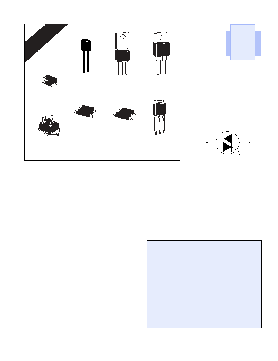
Triacs
(0.8 A to 35 A)
E2
General Description
These gated triacs from Teccor Electronics are part of a broad
line of bidirectional semiconductors. The devices range in current
ratings from 0.8 A to 35 A and in voltages from 200 V to 1000 V.
The triac may be gate triggered from a blocking to conduction
state for either polarity of applied voltage and is designed for AC
switching and phase control applications such as speed and tem-
perature modulation controls, lighting controls, and static switch-
ing relays. The triggering signal is normally applied between the
gate and MT1.
Isolated packages are offered with internal construction, having
the case or mounting tab electrically isolated from the semicon-
ductor chip. This feature facilitates the use of low-cost assembly
and convenient packaging techniques. Tape-and-reel capability
is available. See "Packing Options" section of this catalog.
All Teccor triacs have glass-passivated junctions to ensure long-
term device reliability and parameter stability. Teccor's glass-
passivated junctions offer a rugged, reliable barrier against junc-
tion contamination.
Variations of devices covered in this data sheet are available for
custom design applications. Consult factory for more information.
R
oHS
Features
∑
RoHS Compliant
∑
Electrically-isolated packages
∑
Glass-passivated junctions
∑
Voltage capability -- up to 1000 V
∑
Surge capability -- up to 200 A
Compak Package
∑
Surface mount package -- 0.8 A and 1 A series
∑
New small profile three-leaded Compak package
∑
Packaged in embossed carrier tape with 2,500
devices per reel
∑
Can replace SOT-223
E2
MT2
MT1
G
*TO-220
3-lead
Compak
TO-92
TO-251
V-Pak
TO-263
D
2
Pak
TO-92
TO-252
D-Pak
*TO-3
Fastpak
TO-202
Triacs
Data Sheets
http://www.littelfuse.com
E2 - 2
©2004 Littelfuse, Inc.
+1 972-580-7777
Thyristor Product Catalog
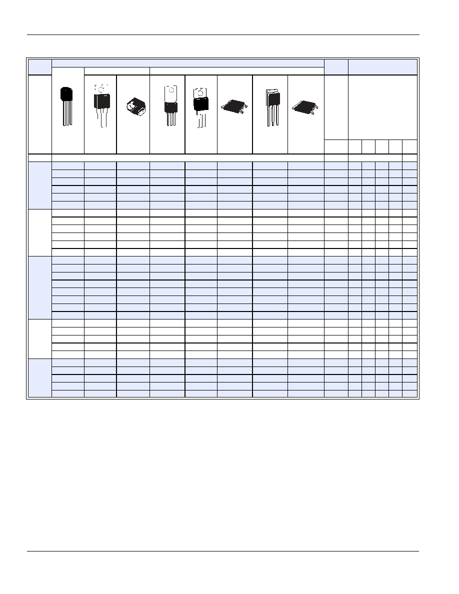
See "General Notes" on page E2 - 4 and "Electrical Specification Notes" on page E2 - 5.
I
T(RMS)
Part Number
V
DRM
I
GT
Isolated
Non-isolated
(4)
TO-92
TO-220
Compak
TO-202
TO-220
TO-252
D-Pak
TO-251
V-Pak
TO-263
D
2
Pak
(1)
Volts
(3) (7) (15)
mAmps
QI
QII QIII QIV
QIV
MAX
See "Package Dimensions" section for variations. (11)
MIN
MAX
TYP
0.8 A
Q2X8E3
Q2X3
200
10
10
10
25
Q4X8E3
Q4X3
400
10
10
10
25
Q6X8E3
Q6X3
600
10
10
10
25
Q2X8E4
Q2X4
200
25
25
25
50
Q4X8E4
Q4X4
400
25
25
25
50
Q6X8E4
Q6X4
600
25
25
25
50
1 A
Q201E3
Q2N3
200
10
10
10
25
Q401E3
Q4N3
400
10
10
10
25
Q601E3
Q6N3
600
10
10
10
25
Q201E4
Q2N4
200
25
25
25
50
Q401E4
Q4N4
400
25
25
25
50
Q601E4
Q6N4
600
25
25
25
50
4 A
Q2004L3
Q2004F31
Q2004D3
Q2004V3
200
10
10
10
25
Q4004L3
Q4004F31
Q4004D3
Q4004V3
400
10
10
10
25
Q6004L3
Q6004F31
Q6004D3
Q6004V3
600
10
10
10
25
Q2004L4
Q2004F41
Q2004D4
Q2004V4
200
25
25
25
50
Q4004L4
Q4004F41
Q4004D4
Q4004V4
400
25
25
25
50
Q6004L4
Q6004F41
Q6004D4
Q6004V4
600
25
25
25
50
Q8004L4
Q8004D4
Q8004V4
800
25
25
25
50
QK004L4
QK004D4
QK004V4
1000
25
25
25
50
6 A
Q2006L4
Q2006F41
Q2006R4
Q2006N4
200
25
25
25
50
Q4006L4
Q4006F41
Q4006R4
Q4006N4
400
25
25
25
50
Q6006L5
Q6006F51
Q6006R5
Q6006N5
600
50
50
50
75
Q8006L5
Q8006R5
Q8006N5
800
50
50
50
75
QK006L5
QK006R5
QK006N5
1000
50
50
50
75
8 A
Q2008L4
Q2008F41
Q2008R4
Q2008N4
200
25
25
25
50
Q4008L4
Q4008F41
Q4008R4
Q4008N4
400
25
25
25
50
Q6008L5
Q6008F51
Q6008R5
Q6008N5
600
50
50
50
75
Q8008L5
Q8008R5
Q8008N5
800
50
50
50
75
QK008L5
QK008R5
QK008N5
1000
50
50
50
75
MT1
G
MT2
MT1
MT2
G
G
MT1
MT2
MT1
G
MT2
MT2
MT1
G
MT2
MT2
MT2
MT2
MT1
G
MT2
MT2
G
MT1
MT2
MT2
MT1
G
Data Sheets
Triacs
©2004 Littelfuse, Inc.
E2 - 3
http://www.littelfuse.com
Thyristor Product Catalog
+1 972-580-7777
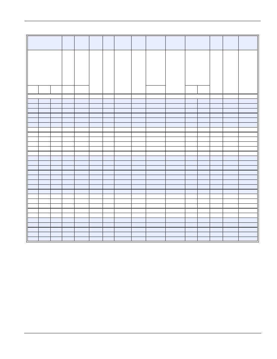
See "General Notes" on page E2 - 4 and "Electrical Specification Notes" on page E2 - 5.
I
DRM
V
TM
V
GT
I
H
I
GTM
P
GM
P
G(AV)
I
TSM
dv/dt(c)
dv/dt
t
gt
I
2
t
di/dt
(1) (16)
mAmps
(1) (5)
Volts
(2) (6)
(15) (18)
(19)
Volts
(1) (8)
(12)
mAmps
(14)
Amps
(14)
Watts
Watts
(9) (13)
Amps
(1) (4) (13)
Volts/µSec
(1)
Volts/
µSec
(10)
µSec
Amp
2
Sec Amps/µSec
T
C
=
25 ∞C
T
C
=
100 ∞C
T
C
=
125 ∞C
T
C
=
25 ∞C
T
C
=
25 ∞C
60/50 Hz
T
C
=
100 ∞C
T
C
=
125 ∞C
MAX
MAX
MAX
MAX
TYP
MIN
TYP
0.02
0.5
1
1.6
2
15
1
10
0.2
10/8.3
1
40
30
2.5
0.41
20
0.02
0.5
1
1.6
2
15
1
10
0.2
10/8.3
1
35
25
2.5
0.41
20
0.02
0.5
1
1.6
2
15
1
10
0.2
10/8.3
1
25
15
2.5
0.41
20
0.02
0.5
1
1.6
2.5
25
1
10
0.2
10/8.3
1
50
40
3
0.41
20
0.02
0.5
1
1.6
2.5
25
1
10
0.2
10/8.3
1
45
35
3
0.41
20
0.02
0.5
1
1.6
2.5
25
1
10
0.2
10/8.3
1
35
25
3
0.41
20
0.02
0.5
1
1.6
2
15
1
10
0.2
20/16.7
1
40
30
2.5
1.6
30
0.02
0.5
1
1.6
2
15
1
10
0.2
20/16.7
1
40
30
2.5
1.6
30
0.02
0.5
1
1.6
2
15
1
10
0.2
20/16.7
1
30
20
2.5
1.6
30
0.02
0.5
1
1.6
2.5
25
1
10
0.2
20/16.7
1
50
40
3
1.6
30
0.02
0.5
1
1.6
2.5
25
1
10
0.2
20/16.7
1
50
40
3
1.6
30
0.02
0.5
1
1.6
2.5
25
1
10
0.2
20/16.7
1
40
30
3
1.6
30
0.05
0.5
2
1.6
2
20
1.2
15
0.3
55/46
2
50
40
2.5
12.5
50
0.05
0.5
2
1.6
2
20
1.2
15
0.3
55/46
2
50
40
2.5
12.5
50
0.05
0.5
2
1.6
2
20
1.2
15
0.3
55/46
2
40
30
2.5
12.5
50
0.05
0.5
2
1.6
2.5
30
1.2
15
0.3
55/46
2
100
75
3
12.5
50
0.05
0.5
2
1.6
2.5
30
1.2
15
0.3
55/46
2
100
75
3
12.5
50
0.05
0.5
2
1.6
2.5
30
1.2
15
0.3
55/46
2
75
50
3
12.5
50
0.05
0.5
2
1.6
2.5
30
1.2
15
0.3
55/46
2
60
40
3
12.5
50
0.05
3
1.6
2.5
30
1.2
15
0.3
55/46
2
50
3
12.5
50
0.05
0.5
2
1.6
2.5
50
1.6
18
0.5
80/65
4
200
120
3
26.5
70
0.05
0.5
2
1.6
2.5
50
1.6
18
0.5
80/65
4
200
120
3
26.5
70
0.05
0.5
2
1.6
2.5
50
1.6
18
0.5
80/65
4
150
100
3
26.5
70
0.05
0.5
2
1.6
2.5
50
1.6
18
0.5
80/65
4
125
85
3
26.5
70
0.05
3
1.6
2.5
50
1.6
18
0.5
80/65
4
100
3
26.5
70
0.05
0.5
2
1.6
2.5
50
1.8
20
0.5
100/83
4
250
150
3
41
70
0.05
0.5
2
1.6
2.5
50
1.8
20
0.5
100/83
4
250
150
3
41
70
0.05
0.5
2
1.6
2.5
50
1.8
20
0.5
100/83
4
220
125
3
41
70
0.05
0.5
2
1.6
2.5
50
1.8
20
0.5
100/83
4
150
100
3
41
70
0.05
3
1.6
2.5
50
1.8
20
0.5
100/83
4
100
3
41
70
Triacs
Data Sheets
http://www.littelfuse.com
E2 - 4
©2004 Littelfuse, Inc.
+1 972-580-7777
Thyristor Product Catalog
Specific Test Conditions
di/dt -- Maximum rate-of-change of on-state current; I
GT
= 200 mA with
0.1
µ
s rise time
dv/dt -- Critical rate-of-rise of off-state voltage at rated V
DRM
gate open
dv/dt(c) -- Critical rate-of-rise of commutation voltage at rated V
DRM
and I
T(RMS)
commutating di/dt = 0.54 rated I
T(RMS)
/ms; gate
unenergized
I
2
t -- RMS surge (non-repetitive) on-state current for period of 8.3 ms
for fusing
I
DRM
-- Peak off-state current, gate open; V
DRM
= maximum rated value
I
GT
-- DC gate trigger current in specific operating quadrants;
V
D
= 12 V dc
I
GTM
-- Peak gate trigger current
I
H
-- Holding current (DC); gate open
I
T(RMS)
-- RMS on-state current conduction angle of 360∞
I
TSM
-- Peak one-cycle surge
P
G(AV)
-- Average gate power dissipation
P
GM
-- Peak gate power dissipation;
I
GT
I
GTM
t
gt
-- Gate controlled turn-on time; I
GT
= 200 mA with 0.1
µ
s rise time
V
DRM
-- Repetitive peak blocking voltage
V
GT
-- DC gate trigger voltage; V
D
= 12 V dc; R
L
= 60
V
TM
-- Peak on-state voltage at maximum rated RMS current
General Notes
∑
All measurements are made at 60 Hz with a resistive load at an
ambient temperature of +25
∞C unless specified otherwise.
∑
Operating temperature range (T
J
) is -65
∞C to +125 ∞C for TO-92,
-25 ∞C to +125 ∞C for Fastpak, and -40
∞C to +125 ∞C for all other
devices.
∑
Storage temperature range (T
S
) is -65
∞C to +150 ∞C for TO-92,
-40
∞C to +150 ∞C for TO-202, and -40 ∞C to +125 ∞C for all other
devices.
∑
Lead solder temperature is a maximum of 230
∞C for 10 seconds,
maximum;
1/16" (1.59 mm) from case.
∑
The case temperature (T
C
) is measured as shown on the dimen-
sional outline drawings. See "Package Dimensions" section of this
catalog.
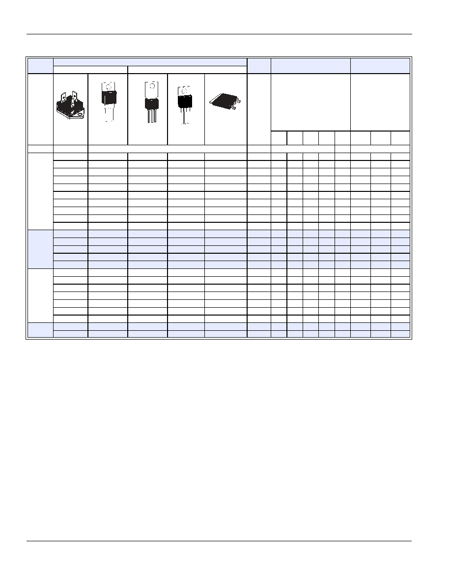
I
T(RMS)
Part Number
V
DRM
I
GT
I
DRM
Isolated
Non-isolated
(4) (16)
TO-3
Fastpak
TO-220
TO-202
TO-220
TO-263
D
2
Pak
(1)
Volts
(3) (7) (15)
mAmps
(1) (16)
mAmps
QI
QII
QIII
QIV
QIV
T
C
=
25 ∞C
T
C
=
100 ∞C
T
C
=
125 ∞C
MAX
See "Package Dimensions" section for variations. (11)
MIN
MAX
TYP
MAX
10 A
Q2010L4
Q2010R4
Q2010N4
200
25
25
25
50
0.05
1
Q4010L4
Q4010R4
Q4010N4
400
25
25
25
50
0.05
1
Q6010L4
Q6010R4
Q6010N4
600
25
25
25
50
0.05
1
Q8010L4
Q8010R4
Q8010N4
800
25
25
25
50
0.1
1
QK010L4
QK010R4
QK010N4
1000
25
25
25
50
0.1
3
Q2010L5
Q2010F51
Q2010R5
Q2010N5
200
50
50
50
75
0.05
0.5
2
Q4010L5
Q4010F51
Q4010R5
Q4010N5
400
50
50
50
75
0.05
0.5
2
Q6010L5
Q6010F51
Q6010R5
Q6010N5
600
50
50
50
75
0.05
0.5
2
Q8010L5
Q8010R5
Q8010N5
800
50
50
50
75
0.1
0.5
2
QK010L5
QK010R5
QK010N5
1000
50
50
50
75
0.1
3
15 A
Q2015L5
Q2015R5
Q2015N5
200
50
50
50
0.05
0.5
2
Q4015L5
Q4015R5
Q4015N5
400
50
50
50
0.05
0.5
2
Q6015L5
Q6015R5
Q6015N5
600
50
50
50
0.05
0.5
2
Q8015L5
Q8015R5
Q8015N5
800
50
50
50
0.1
1
3
QK015L5
QK015R5
QK015N5
1000
50
50
50
0.1
3
25 A
Q2025R5
Q2025N5
200
50
50
50
0.1
1
3
Q4025R5
Q4025N5
400
50
50
50
0.1
1
3
Q6025R5
Q6025N5
600
50
50
50
0.1
1
3
Q8025R5
Q8025N5
800
50
50
50
0.1
1
3
QK025R5
QK025N5
1000
50
50
50
0.1
3
Q6025P5
600
50
50
50
120
0.1
5
Q8025P5
800
50
50
50
120
0.1
5
35 A
Q6035P5
600
50
50
50
120
0.1
5
Q8035P5
800
50
50
50
120
0.1
5
MT1
MT2
Gate
MT1
MT2
G
MT1
G
MT2
MT2
MT1
G
MT2
MT2
MT2
MT2
MT1
G
Data Sheets
Triacs
©2004 Littelfuse, Inc.
E2 - 5
http://www.littelfuse.com
Thyristor Product Catalog
+1 972-580-7777
Electrical Specification Notes
(1) For either polarity of MT2 with reference to MT1 terminal
(2) For either polarity of gate voltage (V
GT
) with reference to MT1
terminal
(3) See Gate Characteristics and Definition of Quadrants.
(4) See Figure E2.1 through Figure E2.7 for current rating at specific
operating temperature.
(5) See Figure E2.8 through Figure E2.10 for i
T
versus v
T
.
(6) See Figure E2.12 for V
GT
versus T
C
.
(7) See Figure E2.11 for I
GT
versus T
C
.
(8) See Figure E2.14 for I
H
versus T
C
.
(9) See Figure E2.13 for surge rating with specific durations.
(10) See Figure E2.15 for t
gt
versus I
GT
.
(11) See package outlines for lead form configurations. When ordering
special lead forming, add type number as suffix to part number.
(12) Initial on-state current = 200 mA dc for 0.8 A to10 A devices,
400 mA dc for 15 A to 35 A devices
(13) See Figure E2.1 through Figure E2.6 for maximum allowable case
temperature at maximum rated current.
(14) Pulse width
10
µ
s;
I
GT
I
GTM
(15) R
L
= 60
for 0.8 A to10 A triacs; R
L
= 30
for 15 A to 35 A triacs
(16) T
C
= T
J
for test conditions in off state
(17) I
GT
= 300 mA for 25 A and 35 A devices
(18) Quadrants I, II, III only
(19) Minimum non-trigger V
GT
at 125 ∞C is 0.2 V for all except 50 mA
MAX QIV devices which are 0.2 V at 110 ∞C.
Gate Characteristics
Teccor triacs may be turned on between gate and MT1 terminals
in the following ways:
∑
In-phase signals (with standard AC line) using Quadrants I
and III
∑
Application of unipolar pulses (gate always positive or nega-
tive), using Quadrants II and III with negative gate pulses and
Quadrants I and IV with positive gate pulses
However, due to higher gate requirements for Quadrant IV, it
is recommended that only negative pulses be applied. If pos-
itive pulses are required, see "Sensitive Triacs" section of
this catalog or contact the factory. Also, see
Figure AN1002.8, "Amplified Gate" Thyristor Circuit.
V
TM
V
GT
I
H
I
GTM
P
GM
P
G(AV)
I
TSM
dv/dt(c)
dv/dt
t
gt
I
2
t
di/dt
(1) (5)
Volts
(2) (6) (15)
(18) (19)
Volts
(1) (8) (12)
mAmps
(14)
Amps
(14)
Watts
Watts
(9) (13)
Amps
(1) (4) (13)
Volts/µSec
(1)
Volts/
µSec
(10) (17)
µSec
Amps
2
Sec Amps/µSec
T
C
= 25 ∞C
T
C
= 25 ∞C
60/50 Hz
T
C
=
100 ∞C
T
C
=
125 ∞C
MAX
MAX
MAX
TYP
MIN
TYP
1.6
2.5
35
1.8
20
0.5
120/100
2
150
3
60
70
1.6
2.5
35
1.8
20
0.5
120/100
2
150
3
60
70
1.6
2.5
35
1.8
20
0.5
120/100
2
100
3
60
70
1.6
2.5
35
1.8
20
0.5
120/100
2
75
3
60
70
1.6
2.5
35
1.8
20
0.5
120/100
2
50
3
60
70
1.6
2.5
50
1.8
20
0.5
120/100
4
350
225
3
60
70
1.6
2.5
50
1.8
20
0.5
120/100
4
350
225
3
60
70
1.6
2.5
50
1.8
20
0.5
120/100
4
300
200
3
60
70
1.6
2.5
50
1.8
20
0.5
120/100
4
250
175
3
60
70
1.6
2.5
50
1.8
20
0.5
120/100
4
150
3
60
70
1.6
2.5
70
2
20
0.5
200/167
4
400
275
4
166
100
1.6
2.5
70
2
20
0.5
200/167
4
400
275
4
166
100
1.6
2.5
70
2
20
0.5
200/167
4
350
225
4
166
100
1.6
2.5
70
2
20
0.5
200/167
4
300
200
4
166
100
1.6
2.5
70
2
20
0.5
200/167
4
200
4
166
100
1.8
2.5
100
2
20
0.5
200/167
5
400
275
4
166
100
1.8
2.5
100
2
20
0.5
200/167
5
400
275
4
166
100
1.8
2.5
100
2
20
0.5
200/167
5
350
225
4
166
100
1.8
2.5
100
2
20
0.5
200/167
5
300
200
4
166
100
1.8
2.5
100
2
20
0.5
200/167
5
200
4
166
100
1.4
2.75
50
2
20
0.5
250/220
5
550
475
3
260
100
1.4
2.75
50
2
20
0.5
250/220
5
450
400
3
260
100
1.5
2.75
50
2
20
0.5
350/300
5
550
475
3
508
100
1.5
2.75
50
2
20
0.5
350/300
5
450
400
3
508
100