Silicon Avalanche Diodes
286
w w w . l i t t e l f u s e . c o m
500 Watt Axial Leaded Transient Voltage Suppressors
Æ
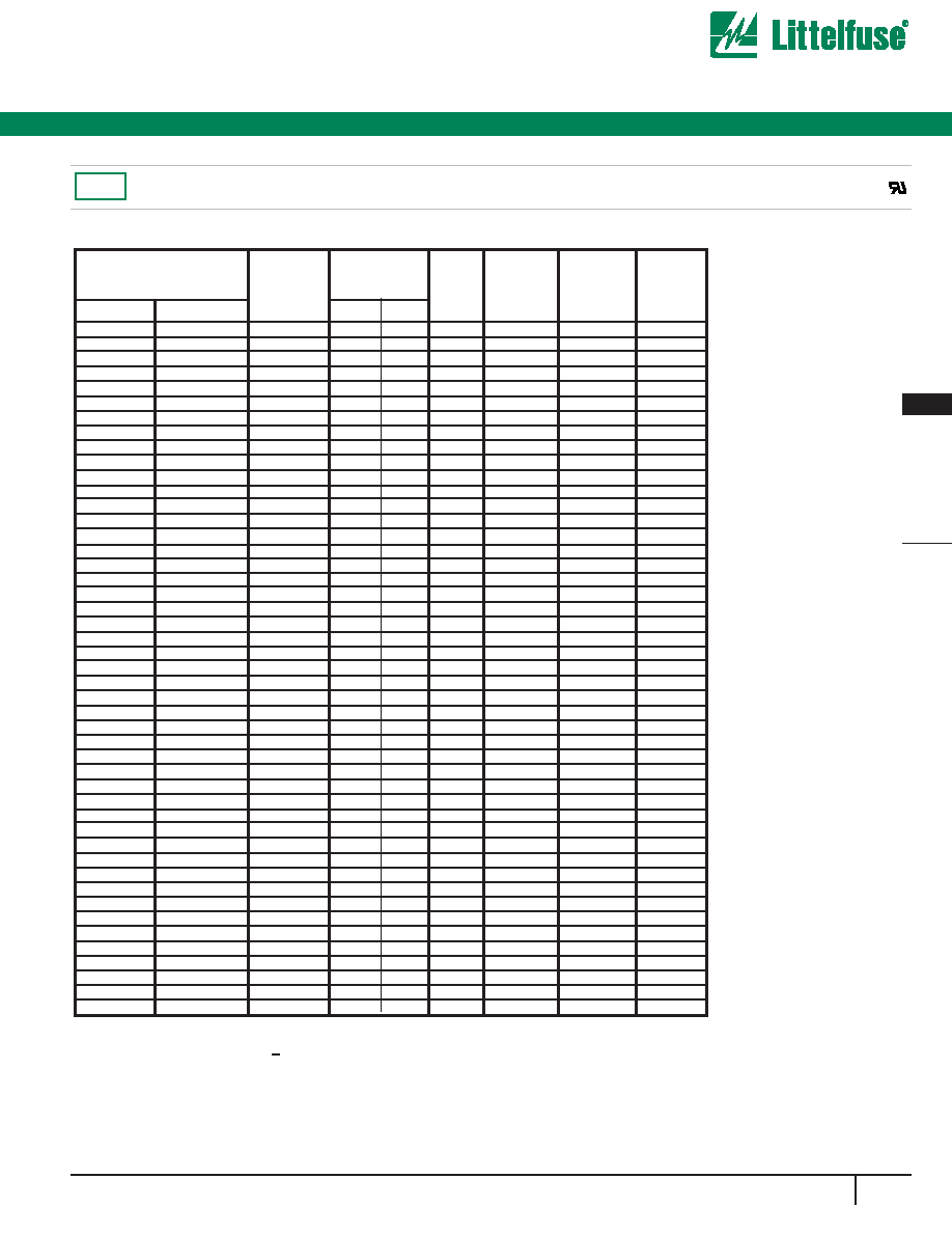
MAXIMUM RATINGS AND CHARACTERISTICS @25∞C
AMBIENT TEMPERATURE (unless otherwise noted)
UNIT
Watts
Amps
Watts
Amps
∞C
Notes:
1. Non-repetitive current pulse, per Fig.3 and derated above
TA= 25∞C per Fig.2
2. Mounted on Copper Pad area of 1.6x1.6"(40x40mm)
per Fig.5.
3. 8.3 ms single half sine-wave, or equivalent square wave, Duty
cycle= 4 pulses per minutes maximum.
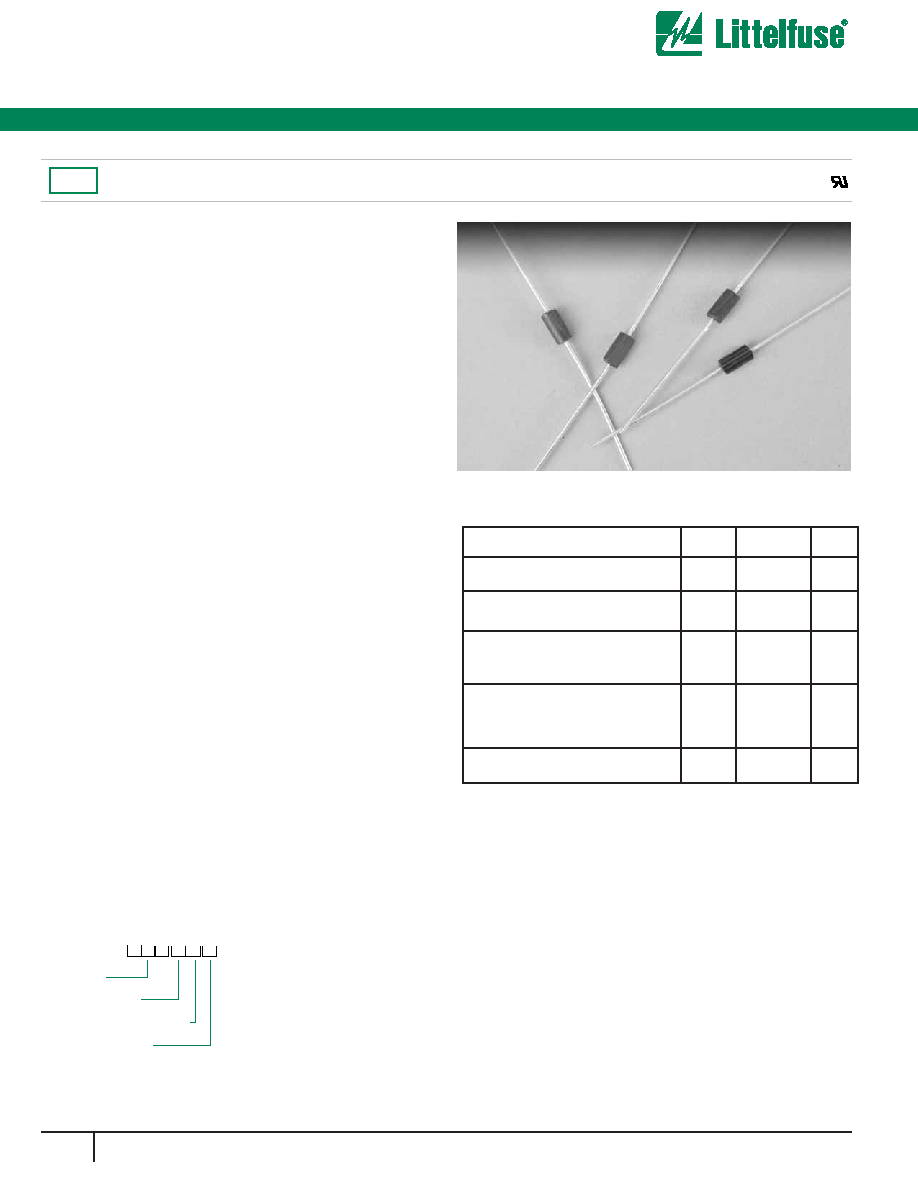
The SA Series is designed specifically to protect sensitive
electronics equipment from voltage transients induced by
lightning and other transient voltage events. These devices are
ideal for the protection of I/O interfaces, Vcc bus and other
vulnerable circuits used in computer and consumer electronic
applications.
FEATURES
∑
RoHS
Compliant
∑
5.0 to 180 Volts
∑
Uni-directional and Bi-directional
∑
Glass passivated chip junction
∑
500W peak pulse power capability on 10/1000µs waveform
∑
Excellent clamping capability
∑
Repetition rate (duty cycle): 0.01%
∑
Low incremental surge resistance
∑
Fast response time: typically less than 1.0ps from 0 Volts to
BV for unidirectional and 5.0ns for bidirectional types
∑
Typical IR less than 1µA above 10V
∑
High temperature soldering guaranteed: 265∞C/10
seconds/.375",(9.5mm) lead length, 5lbs.,(2.3kg) tension
Agency Approvals:
Recognized under the Components
Program of Underwriters Laboratories.
Agency File Number:
E128662
SA
C A
Voltage
Bi-Directional
5% Voltage Tolerance
Packing Option
B = Bulk (1000 pcs)
T = Tape and reeled (4000 pcs)
SYMBOL
PPPM
IPPM
PM(AV)
IFSM
Tj, TSTG
VALUE
Min
500
SEE
TABLE 1
3
70
-55 to +175
RATING
Peak Pulse Power Dissipation on
10/1000µs waveform(Note 1, FIG. 1)
Peak Pulse Current of on 10/1000µs
waveform (Note 1, FIG. 3)
Steady State Power Dissipation at
TL=75∞C, Lead lengths .375",
(9.5mm)(Note 2)
Peak Forward Surge Current, 8.3ms
Single Half Sine-Wave Superimposed
on Rated Load, (JEDEC Method)
(Note 3)
Operating junction and Storage
Temperature Range
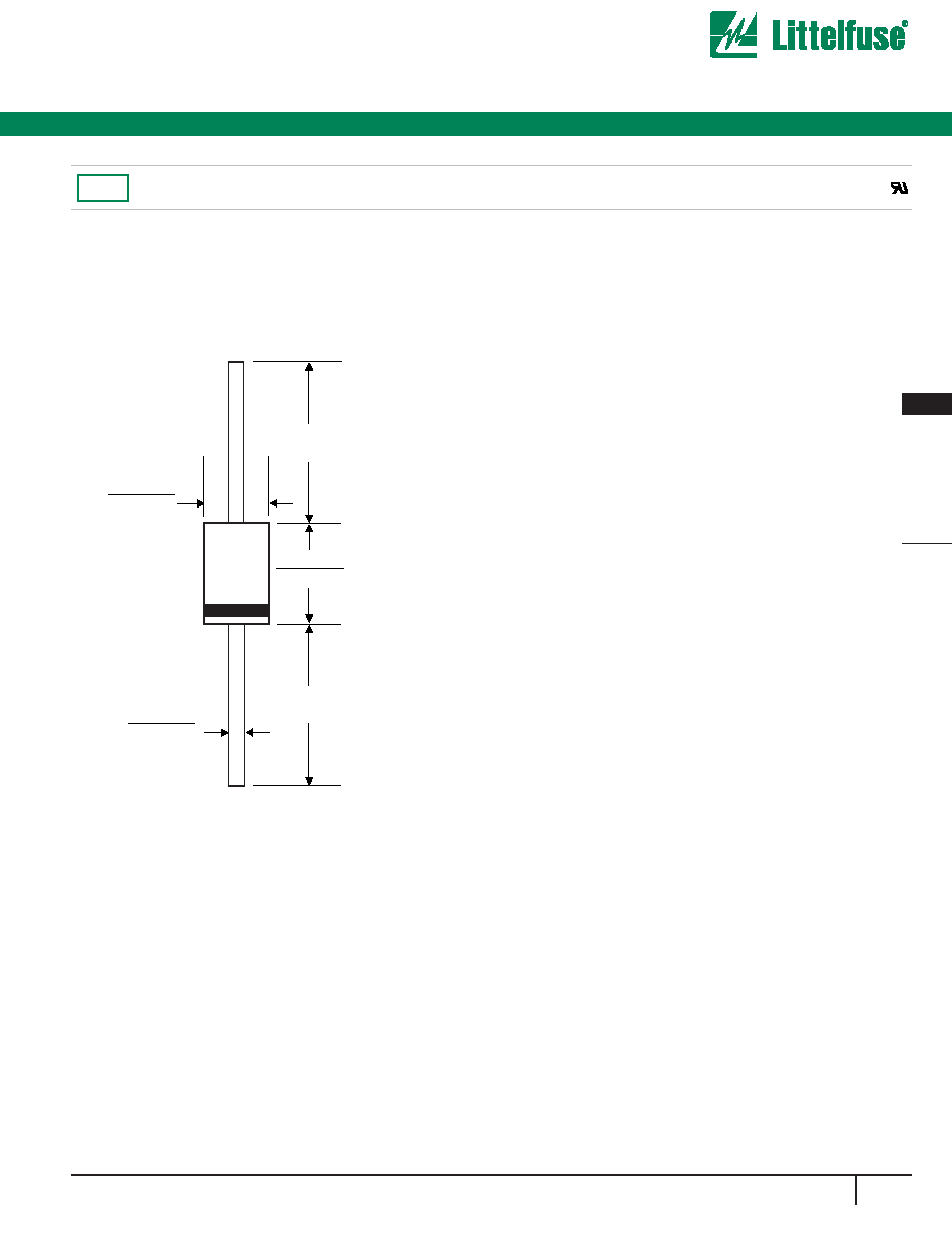
Mechanical Specifications:
Weight:
0.015 ounce, 0.4 gram
Case:
JEDEC DO-15 Molded Plastic over
passivated junction
Mounting Position:
Any
Polarity:
Color band denotes cathode except
Bidirectional
Terminal:
Plated Axial leads, solderable per
MIL-STD-750, Method 2026
ORDERING INFORMATION
SA Series
RoHS
Silicon Avalanche Diodes
288
w w w . l i t t e l f u s e . c o m
500 Watt Axial Leaded Transient Voltage Suppressors
Æ
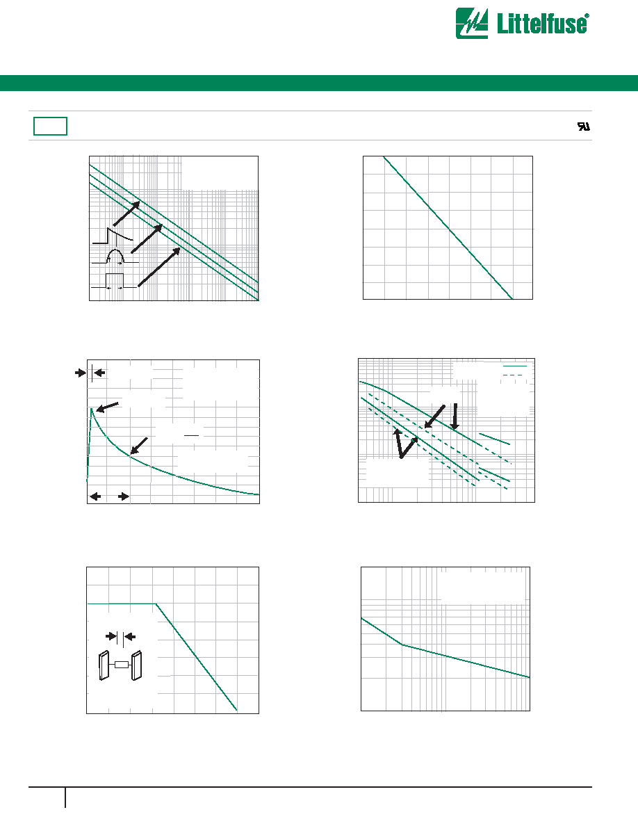
Fig. 1 Peak Pulse Power Rating Curve
P
PPM
- Peak Pulse Power (KW)
0.1s
1.0s
10s
100s
1.0ms
10ms
0.1
1
10
30
Non-repetitive Pulse
Waveform Shown in Fig. 3
TA=25∞C
td- Pulse Width (sec.)
Fig. 2 Pulse Derating Curve
TA- Ambient Temperature (∞C)
Peak Pulse Power (P
PP
) or Current (I
PP
)
Derating in Percentage, %
0
0
25
25
50
50
75
75
100
100
125 150 175 200
Fig. 3 Pulse Waveform
I PPM
- Peak Pulse Current, % I
RSM
0
0
50
100
150
1.0
2.0
3.0
4.0
tr=10µsec
Peak Value
IPPM
Half Value IPPM
2
TJ=25∞C
Pulse Width(td) is defined
as the point where the peak
current decays to 50% of IPPM
10/1000µsec. Waveform
as defined by R.E.A
td
t-Time (ms)
Fig. 6- Maximum Non-Repetitive
I PSM
-Peak Forward Surge Current (A)
1
10
100
200
10
100
Number of Cycles at 60Hz
Forward Surge Current
Uni-Directional Only
8.3 Single Half Sine-Wave
(JEDEC Method)
Undirectional Only
Fig. 4- Typical Junction Capacitance
C
J-Junction Capacitance (pF)
6000
1000
100
10
5
100
500
VWM-Reverse Stand-Off Voltage (V)
VR=Rated
Stand-Off Voltage
TJ=25∞C
f=1MHZ
Vsig=50mVp-p
Uni-Directional
Bi-Directional
VR=
Fig. 5 Steady State Power
Derating Curve
T1- Lead Temperature (∞C)
Steady State Power Dissipation (W)
0
0
25
1.0
50
2.0
75
3.0
100
4.0
125 150 175 200
L=0.375"(9.5mm)
Lead Lengths
1.6x1.6x.040
(40x40x1mm)
Copper Heat Sinks
P
P
P
Td
Td
Td
Half SINE
Exponential
Square
SA Series
RoHS