95
w w w . l i t t e l f u s e . c o m
2
V
ARIST
OR
PR
ODUCTS
Varistor Products
High Energy Industrial Thermally Protected
TMOV34S
Æ
Varistor Series
Æ
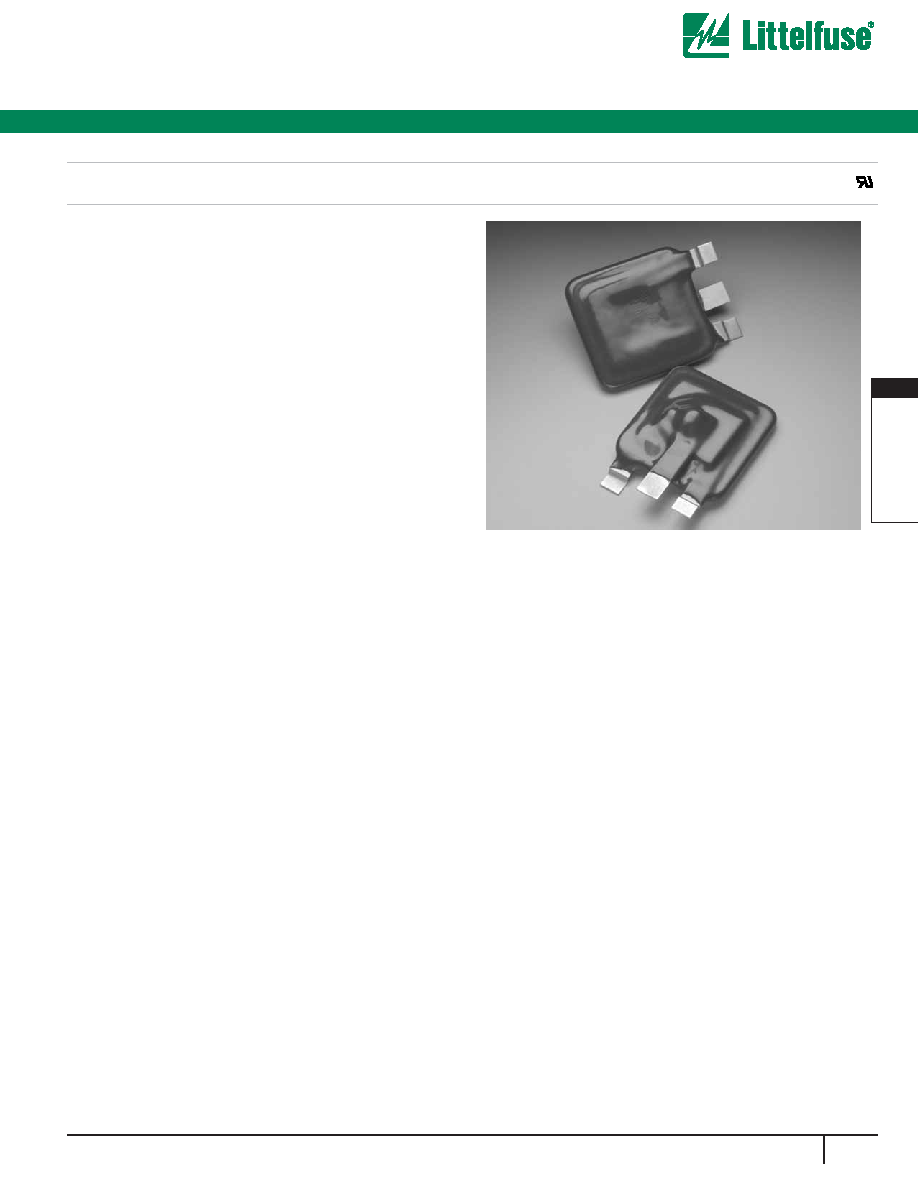
The Littelfuse Industrial TMOV34S series thermally protected varistor
represents a new development in circuit protection. It consists of a 34mm
square format varistor element ( MOV) with an integral thermally activated
element designed to open in the event of overheating due to abnormal
over-voltage, limited current conditions as outlined in UL1449 Feb. 1998
edition.The device has a third lead, an indicator lead, which may be used
to indicate that the MOV has been disconnected from the circuit. This lead
facilitates connection to monitoring circuitry. The TMOV34S devices offer
quick thermal response due to the close proximity of the integrated ther-
mal element to the MOV body. The integrated configuration also offers
lower inductance than most discreet solutions resulting in improved
clamping performance to fast over-voltage transients.
Features
∑ US Patent for Thermally Protected MOV- Patent # 6636403
∑ Designed to facilitate compliance to UL1449 for TVSS product.
∑ Hi Peak Current Rating to 40 kA.
∑ -55 Deg C to +85 Deg C operating temp.
∑ Agency Recognition : UL
∑ Alternative Design available with narrow
3mm wide monitor (right) lead.
AGENCY APPROVALS:
Recognized by UL under File UL E75901
34mm Devices-Devices are approved as an MOV to UL1449. Devices with
ratings greater than 420VAC are not affected by these abnormal voltage con-
ditions.
Accelerated Aging Testing-34mm devices comply with Acclerated Aging
Test requirements per. ANSI/IEEE C62.11 and may be used in secondary
surge arrestors.
AGENCY FILE NUMBERS: ULE75961 (UL1449)
Applications
∑ TVSS Products
∑ AC Panel Protection Modules
∑ AC Line Power Supplies
∑ AC Power Meters
∑ UPS (Uninterruptable Power Supply)
∑ Inverters
∑ AC/DC Power Supplies
∑ DIN Rail
96
w w w . l i t t e l f u s e . c o m
Varistor Products
High Energy Industrial Thermally Protected
TMOV34S
Æ
Varistor Series
MAXIMUM RATING (85∞C)
SPECIFICATIONS (25∞C)
CONTINUOUS
TRANSIENT
AC
DC
VOLTS
VOLTS
ENERGY
2ms
PEAK SURGE
CURRENT
8/20µs
VARISTOR
VOLTAGE AT 1mA
TEST CURRENT
MAXIMUM
CLAMPING VOLTAGE
8/20µs at
200A
TYPICAL
CAPACITANCE
f = 1MHz
VM(AC)RMS
VM(AC)RMS
VM(AC)
VN(DC)
MIN
VN(DC)
MAX
VC
C
PART
NUMBER
(V)
(J)
(V)
(V)
(pF)
MCOV
SURGE
ARRESTER
(V)
ITM
1 x PULSE
WTM
1 x PULSE
(A)
TMOV34S111M
115
150
98
235
40000
1
163
202
305
11500
TMOV34S131M
130
175
111
270
40000
2
184
228
345
10000
TMOV34S141M
140
188
119
291
40000
3
198
248
375
9000
TMOV34S151M
150
200
128
300
40000
4
212
268
405
8000
TMOV34S181M
180
240
153
330
40000
5
254
312
488
6800
TMOV34S201M
200
265
170
335
40000
283
357
540
6500
TMOV34S251M
250
330
213
370
40000
354
429
650
5000
TMOV34S271M
275
369
234
400
40000
389
473
730
4500
TMOV34S301M
300
400
255
435
40000
433
528
780
4050
TMOV34S321M
320
420
272
460
40000
462
561
830
3800
TMOV34S331M
330
435
281
475
40000
476
581
855
3700
TMOV34S351M
350
460
298
500
40000
505
616
910
3500
TMOV34S391M
385
506
327
550
40000
555
678
1005
3300
TMOV34S421M
6
420
560
357
600
40000
610
748
1130
3000
TMOV34S461M
6
460
610
391
620
40000
642
783
1188
2800
TMOV34S481M
6
480
640
408
650
40000
670
825
1240
2700
TMOV34S511M
6
510
675
434
700
40000
735
910
1350
2500
TMOV34S551M
6
550
700
468
735
40000
770
939
1415
2250
TMOV34S571M
6
575
730
489
770
40000
805
1000
1480
2200
TMOV34S621M
6
620
800
527
840
40000
880
1074
1589
2100
TMOV34S661M
6
660
850
561
900
40000
940
1160
1720
2000
TMOV34S681M
6
680
890
578
950
40000
980
1195
1772
1970
TMOV34S751M
6
750
970
638
1050
40000
1080
1320
2000
1800
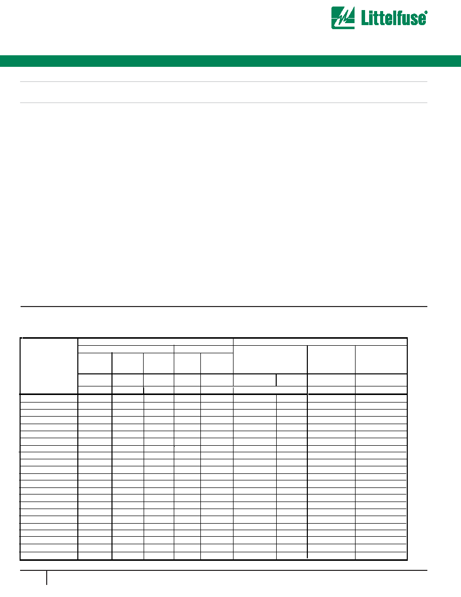
Absolute Maximum Ratings
For ratings of individual members of a series, see Device Ratings and Specifications chart
Continuous:
Steady State Applied Voltage:
AC Voltage Range (VM(AC)RMS) . . . . . . . . . . . . . . . . . . . . . . . . . . . . . . . . . . . . . . . . . . . . . . . . . . . . . . . . . . . . . . . . . 115 to 750
V
Transient:
Peak Pulse Current (ITM)
For 8x20µs Current Wave, single pulse. . . . . . . . . . . . . . . . . . . . . . . . . . . . . . . . . . . . . . . . . . . . . . . . . . . . . . up to 40,000
A
Single-Pulse Energy Capability
For 2ms Current Wave . . . . . . . . . . . . . . . . . . . . . . . . . . . . . . . . . . . . . . . . . . . . . . . . . . . . . . . . . . . . . . . . . . . 235 to 1050
J
Operating Ambient Temperature Range (TA). . . . . . . . . . . . . . . . . . . . . . . . . . . . . . . . . . . . . . . . . . . . . . . . . . . . . . . . . -55 to +85
∞C
Storage Temperature (TSTG). . . . . . . . . . . . . . . . . . . . . . . . . . . . . . . . . . . . . . . . . . . . . . . . . . . . . . . . . . . . . . . . . . . . -55 to +125
o
C
Temperature Coefficient (
V) of Clamping Voltage (VC) at Specified Test Current . . . . . . . . . . . . . . . . . . . . . . . . . . . . . . . <0.01
%/
o
C
Hi-Pot Encapsulation (Isolation Voltage Capability) . . . . . . . . . . . . . . . . . . . . . . . . . . . . . . . . . . . . . . . . . . . . . . . . . . . . . . . . 2500
V
Thermal Protection Isolation Voltage Capability (when operated)
-Under UL1449 Limited Current Test Procedure-see Note #1. . . . . . . . . . . . . . . . . . . . . . . . . . . . . . . . . . . . . . . . . . . . . . . 600
V
Insulation Resistance . . . . . . . . . . . . . . . . . . . . . . . . . . . . . . . . . . . . . . . . . . . . . . . . . . . . . . . . . . . . . . . . . . . . . . . . . . . . . . 1,000
M
I#1 - Under Ul1449 limited current testing parts rated >420V will not open due to 600V voltage limit. Devices with ratings >420V have not yet been evaluated.
CAUTION: Stresses above those listed in "Absolute Maximum Ratings" may cause permanent damage to the device. This is a stress only rating and operation of the device
at these or any other conditions above those indicated in the operational sections of this specification is not implied.
Device Ratings and Specifications - TMOV Varistor Series
TM
Absolute Maximum Ratings
UNITS
97
w w w . l i t t e l f u s e . c o m
2
V
ARIST
OR
PR
ODUCTS
Varistor Products
High Energy Industrial Thermally Protected
TMOV34S
Æ
Varistor Series
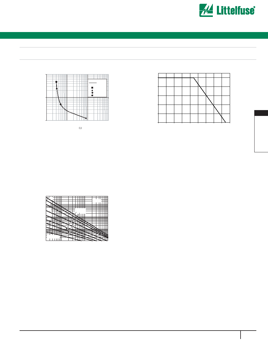
* Figure 4: Typical time to open circuit under UL1449
Abnormal Overvoltage Limited Current Test
0.1
1
10
10
100
1000
10000
Time s
0.125A
0.5A
2.5A
5A
Typical
For applications exceeding 85∫C ambient
temperature, the peak surge current and energy
ratings must be reduced as shown in Figure 3.
Figure 5: Peak Current & Energy Derating Curve
0
20
40
60
80
100
-55
50
60
70
80
90
100
110
120
130
AMBIENT TEMPERATURE (∫C)
PERCENT OF RATED VALU
E
Thermal Characteristics
Note : The Industrial TMOV Series TMOV34S devices are intended, in
conjunction with appropriate enclosure design, to help facilitate TVSS
module compliance to UL 1449, Section 37.4 (abnormal over-voltage lim-
ited current requirements). Under these extreme abnormal over-voltage
conditions, the units will exhibit substantial heating and potential venting
prior to opening. Modules should be designed to contain this possibility.
Application testing is strongly recommended.
Pulse Rating Curves
FIGURE 6. SURGE CURRENT RATING CURVES FOR
HB34, HF34 and HG34
Hx34
50,000
20,000
10,000
5,000
2,000
1,000
500
200
100
50
20
10
20
100
1,000
10,000
SURGE CURRENT (A)
IMPULSE DURATION (µs)
10
1
INDEFINITE
10
5
10
2
2
10
3
10
4
10
6
98
w w w . l i t t e l f u s e . c o m
Varistor Products
High Energy Industrial Thermally Protected
TMOV34S
Æ
Varistor Series
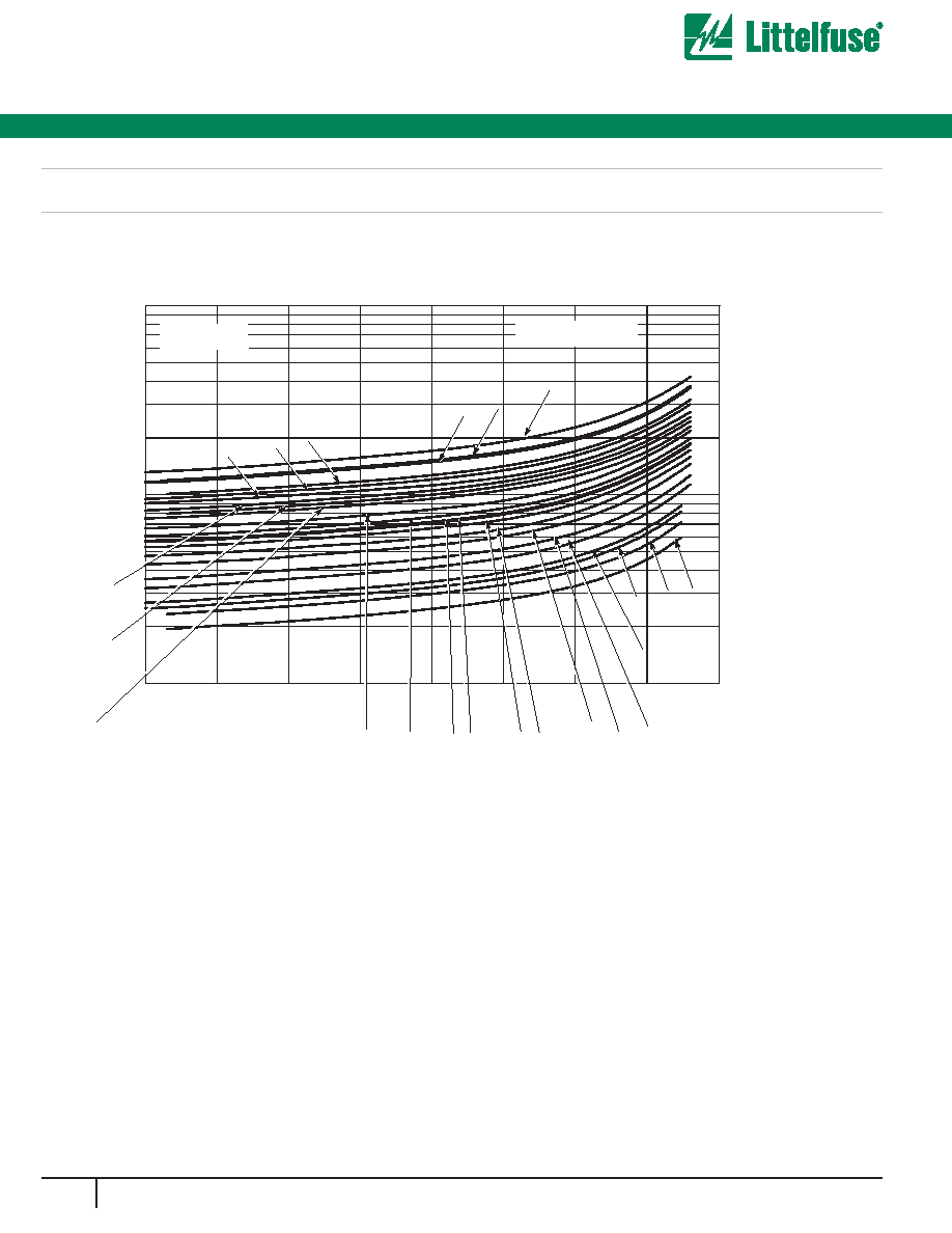
Transient V-I Characteristic Curves
1000
10000
0.001
0.01
0.1
1
10
100
10000
100000
TMOV34S
TA = -55 C to 85C
Current - AMPS
Voltage
Volts
V751
V681
V661
V571
V551
V511
V391
V351 V331 V321
V271
V251 V201 V181
V151
V141
V111
V131
V301
V481
V441
V421
100
1000
Fig 7. V-I Characteristic Curves For TMOV34S
Æ
Varistor
99
w w w . l i t t e l f u s e . c o m
2
V
ARIST
OR
PR
ODUCTS
Varistor Products
High Energy Industrial Thermally Protected
TMOV34S
Æ
Varistor Series
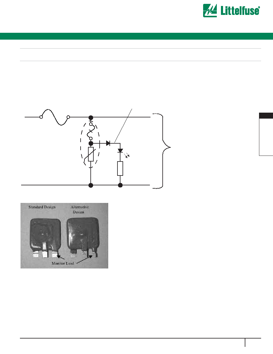
R
LED
Line Fuse
TMOV34S
Neutral
Line
To Protected Circuit
Normally On
Monitor Lead
i
TMOV Varistor Application Examples
The application examples below show how the indicator lead on the
i
TMOV can be used to indicate that the thermal element has been
opened. This signifies that the circuit is no longer protected from
transients by the MOV.
100
w w w . l i t t e l f u s e . c o m
Varistor Products
High Energy Industrial Thermally Protected
TMOV34S
Æ
Varistor Series
Ordering Information
TMOV
34
S
M
150
DEVICE FAMILY
Littelfuse Thermally Protected MOV
DISC DIAMETER (mm)
34 mm
CERAMIC SHAPE
S: Square
Series Designator
M: 3-Leaded TMOV34S Varistor Series
Supplied in Bulk Pack
V
M(AC)RMS
115V to 750V
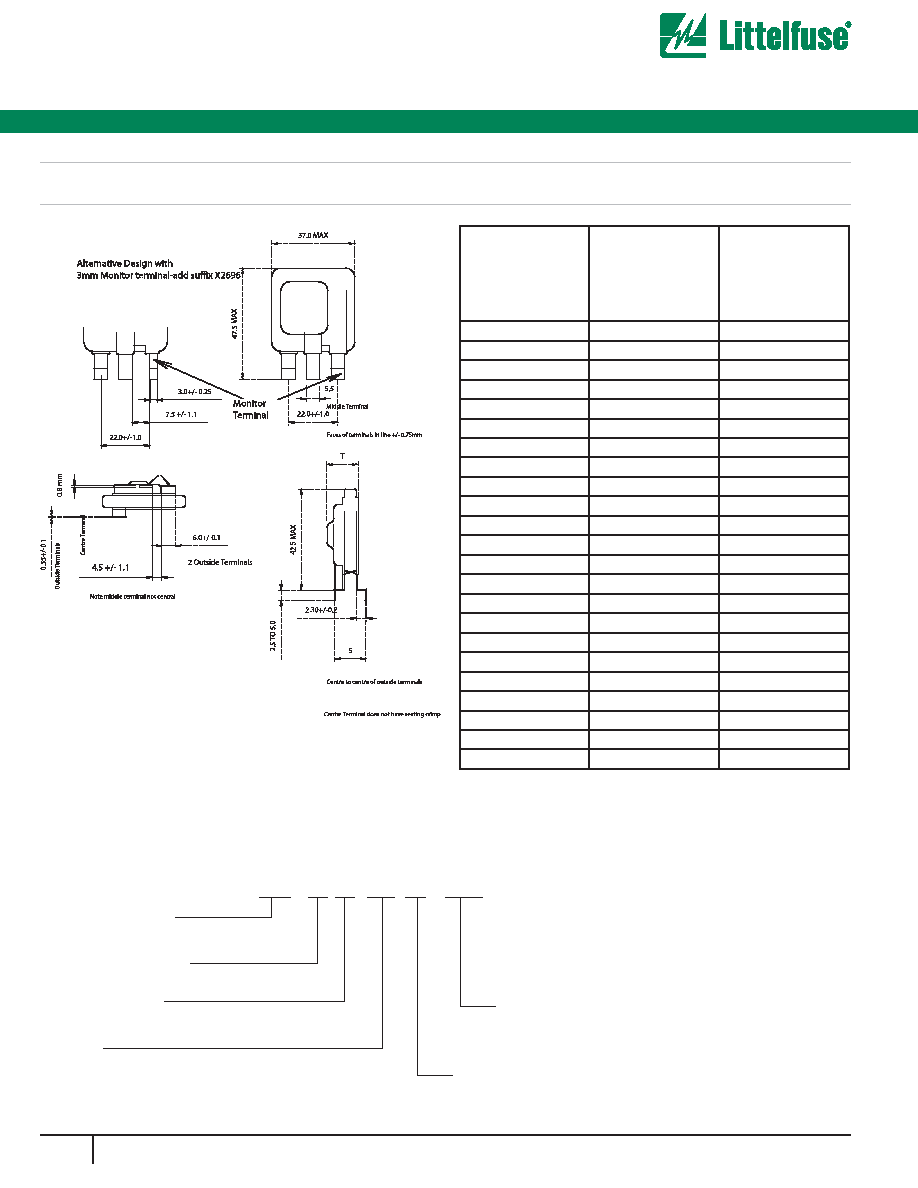
X2696
Optional Design
5 digit suffix when alternative 3mm
wide monitor lead is required
Standard Parts
Part Number
T max
Body Thickness
S
Mounting Terminal
Offset
TMOV34S111M
11.9
5.2 ±.65
TMOV34S131M
12.2
5.5 ±.65
TMOV34S141M
12.3
5.7 ±0.85
TMOV34S151M
12.4
5.9 ±0.85
TMOV34S181M
12.8
6.3 ±0.85
TMOV34S201M
13.0
6.5 ±0.85
TMOV34S251M
11.8
6.25 ±0.85
TMOV34S271M
12.0
6.5 ±0.85
TMOV34S301M
12.3
6.8 ±1.0
TMOV34S321M
12.5
6.9 ±1.0
TMOV34S331M
13.0
7.2 ±1.0
TMOV34S351M
13.1
7.4 ±1.0
TMOV34S391M
13.2
7.6 ±1.0
TMOV34S421M
13.4
7.85 ±1.0
TMOV34S461M
13.7
8.15 ±1.0
TMOV34S481M
13.9
8.25 ±1.0
TMOV34S511M
14.2
8.6 ±1.0
TMOV34S551M
14.8
8.65 ±1.0
TMOV34S571M
15.0
8.85 ±1.0
TMOV34S621M
15.4
9.25 ±1.0
TMOV34S661M
15.8
9.65 ±1.0
TMOV34S681M
16.0
9.85 ±1.0
TMOV34S751M
16.3
10.65 ±1.0
NOTE:
Dimension in mm is typical, unless
To order alternative design with narrow 3mm monitor
lead(right hand terminal as shown) add suffix X2696 to part number
otherwise specified