Surface Mount Varistors
158
w w w . l i t t e l f u s e . c o m
Multilayer Transient Voltage Surge Suppressor
AUML Varistor Series
The AUML Series of Multilayer Transient Surge Suppressors was specifi-
cally designed to suppress the destructive transient voltages found in an
automobile. The most common transient condition results from large
inductive energy discharges. The electronic systems in the automobile,
e.g. antilock brake systems, direct ignition systems, engine control,
airbag control systems, wiper motor controls, etc., are susceptible to
damage from these voltage transients and thus require protection. The
AUML transient suppressors have temperature independent suppression
characteristics affording protection from -55
o
C to 125
o
C.
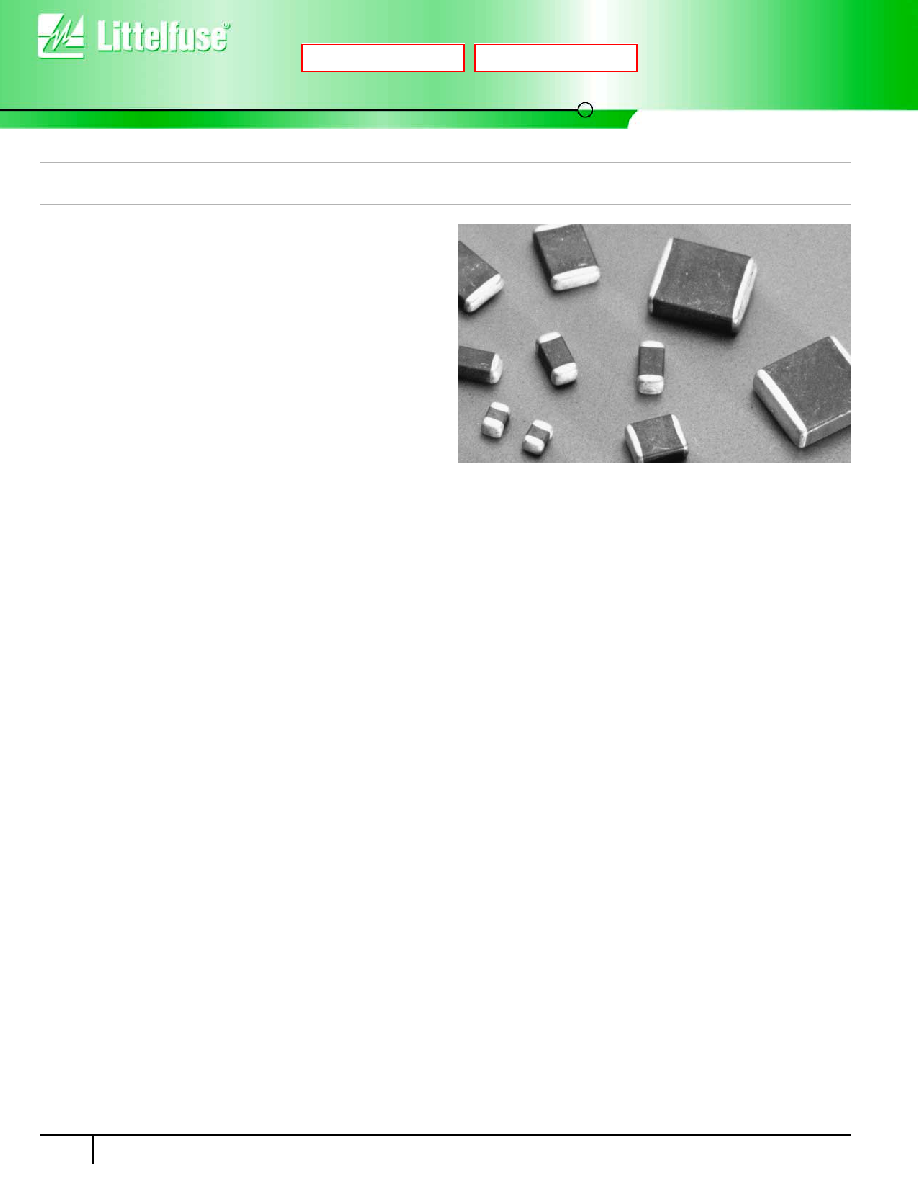
The AUML suppressor is manufactured from semiconducting ceramics
which offer rugged protection and excellent transient energy absorption
in a small package. The devices are available in ceramic leadless chip
form, eliminating lead inductance and assuring fast speed of response to
transient surges. These Suppressors require significantly smaller space
and land pads than silicon TVS diodes, offering greater circuit board
layout flexibility for the designer.
Also see the Littelfuse ML, MLN and MLE Series of Multilayer Suppressors.
Features
∑ Load Dump Energy Rated per SAE Specification J1113
∑ Leadless, Surface Mount Chip Form
∑ "Zero" Lead Inductance
∑ Variety of Energy Ratings Available
∑ No Temperature Derating up to 125
o
C Ambient
∑ High Peak Surge Current Capability
∑ Low Profile, Compact Industry Standard Chip Size; (1206, 1210,
1812 and 2220 Sizes)
∑ Inherent Bidirectional Clamping
∑ No Plastic or Epoxy Packaging Assures Better than 94V-0
Flammability Rating
Next
Previous
AUML Varistor Series
Surface Mount Varistors
Multilayer Transient Voltage Surge Suppressor
159
w w w . l i t t e l f u s e . c o m
3
SURF
A
CE MOUNT
V
ARIST
ORS
Absolute Maximum Ratings
For ratings of individual members of a series, see Device Ratings and Specifications chart
Continuous:
Steady State Applied Voltage:
DC Voltage Range (VM(DC)) . . . . . . . . . . . . . . . . . . . . . . . . . . . . . . . . . . . . . . . . . . . . . . . . . . . . . . . . . . . . . . . . . . . . . . . . . 18
V
Transient:
Load Dump Energy, (WLD) . . . . . . . . . . . . . . . . . . . . . . . . . . . . . . . . . . . . . . . . . . . . . . . . . . . . . . . . . . . . . . . . . . . . . . . . 1.5 to 25
J
Jump Start Capability (5 minutes), (VJUMP). . . . . . . . . . . . . . . . . . . . . . . . . . . . . . . . . . . . . . . . . . . . . . . . . . . . . . . . . . . . . 24.5
V
Operating Ambient Temperature Range (TA). . . . . . . . . . . . . . . . . . . . . . . . . . . . . . . . . . . . . . . . . . . . . . . . . . . . . . . . . . . . . -55 to 125
O
C
Storage Temperature Range (TSTG) . . . . . . . . . . . . . . . . . . . . . . . . . . . . . . . . . . . . . . . . . . . . . . . . . . . . . . . . . . . . . . . . . . -55 to 150
O
C
Temperature Coefficient (
v) of Clamping Voltage (VC) at Specified Test Current . . . . . . . . . . . . . . . . . . . . . . . . . . . . . . . . . . . <0.01
%/
O
C
CAUTION: Stresses above those listed in "Absolute Maximum Ratings" may cause permanent damage to the device. This is a stress only rating and operation of the device
at these or any other conditions above those indicated in the operational sections of this specification is not implied.
Device Ratings and Specifications
Power Dissipation Ratings
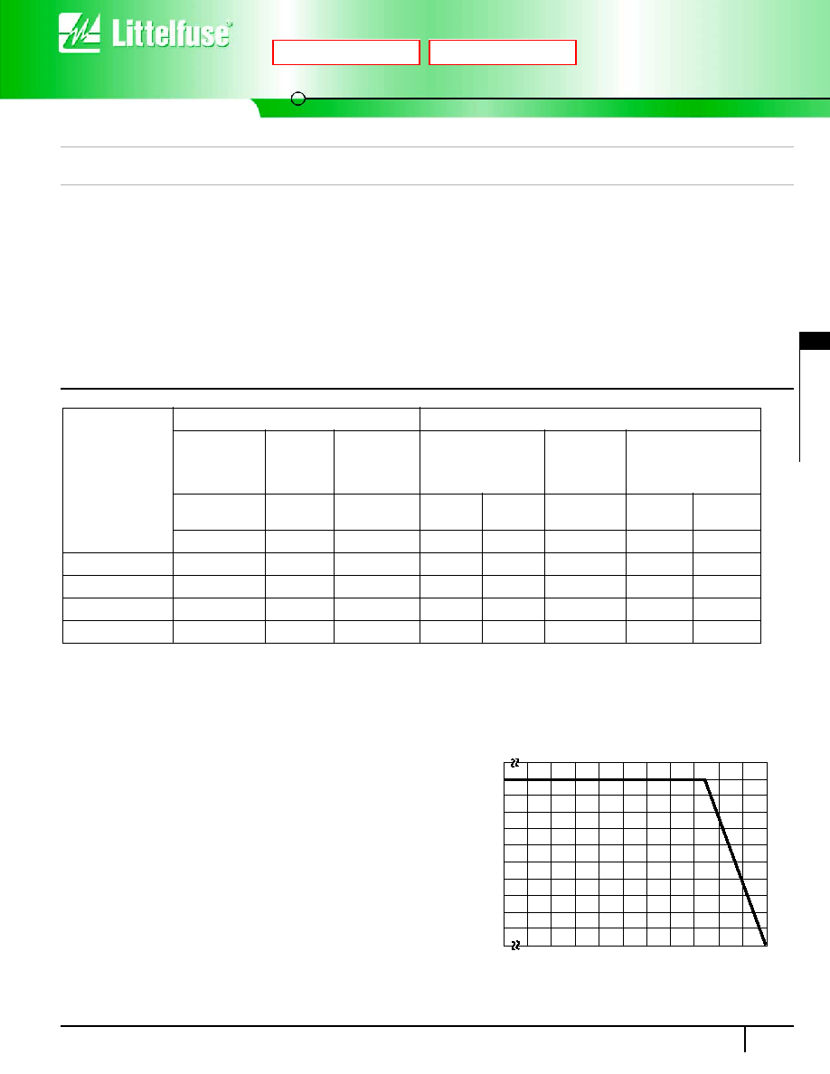
When transients occur in rapid succession, the average power dissipa-
tion is the energy (watt-seconds) per pulse times the number of pulses
per second. The power so developed must be within the specifications
shown on the Device Ratings and Characteristics table for the specific
device. Certain parameter ratings must be derated at high temperatures
as shown in Figure 1.
AUML SERIES UNITS
PART
NUMBER
MAXIMUM RATINGS (125
o
C)
SPECIFICATIONS (25
o
C)
MAXIMUM
CONTINUOUS
DC VOLTAGE
JUMP
START
VOLTAGE
(5 MIN)
LOAD DUMP
ENERGY
(10 PULSES)
NOMINAL VARISTOR
VOLTAGE AT 10mA
DC TEST CURRENT
MAXIMUM
STANDBY
LEAKAGE
(AT 13VDC)
MAXIMUM CLAMPING
VOLTAGE (V
C
)
AT TEST CURRENT
(8/20ms)
V
M(DC)
V
JUMP
W
LD
V
N(DC)
MIN
V
N(DC)
MAX
I
L
V
C
I
P
(V)
(V)
(J)
(V)
(V)
(mA)
(V)
(A)
V18AUMLA1206
18
24.5
1.5
23
32
50
40
1.5
V18AUMLA1210
18
24.5
3
23
32
50
40
1.5
V18AUMLA1812
18
24.5
6
23
32
100
40
5
V18AUMLA2220
18
24.5
25
23
32
200
40
10
NOTES:
1. Average power dissipation of transients not to exceed 0.1W, 0.15W, 0.3W and 1W for model sizes 1206, 1210, 1812 and 2220 respectively.
2. Load dump energy rating (into the suppressor) of a voltage transient with a resultant time constant of 115ms to 230ms.
3. Thermal shock capability per Mil-Std-750, Method 1051: -55
o
C to 125
o
C, 5 minutes at 25
o
C, 25 Cycles: 15 minutes at each extreme.
4. For application specific requirements, please contact Littelfuse.
For automotive 24V and 42V applications please contact your Littelfuse representative or visit www.littelfuse.com for the latest product update.
FIGURE 1. CURRENT, ENERGY AND POWER DERATING
CURVE
100
90
80
70
60
50
40
30
20
10
0
-55
50
60
70
80
90
100 110
120
130
140 150
PERCENT OF RA
TED
V
ALUE
AMBIENT TEMPERATURE (
o
C)
Next
Previous
Multilayer Transient Voltage Surge Suppressor
AUML Varistor Series
Surface Mount Varistors
160
w w w . l i t t e l f u s e . c o m
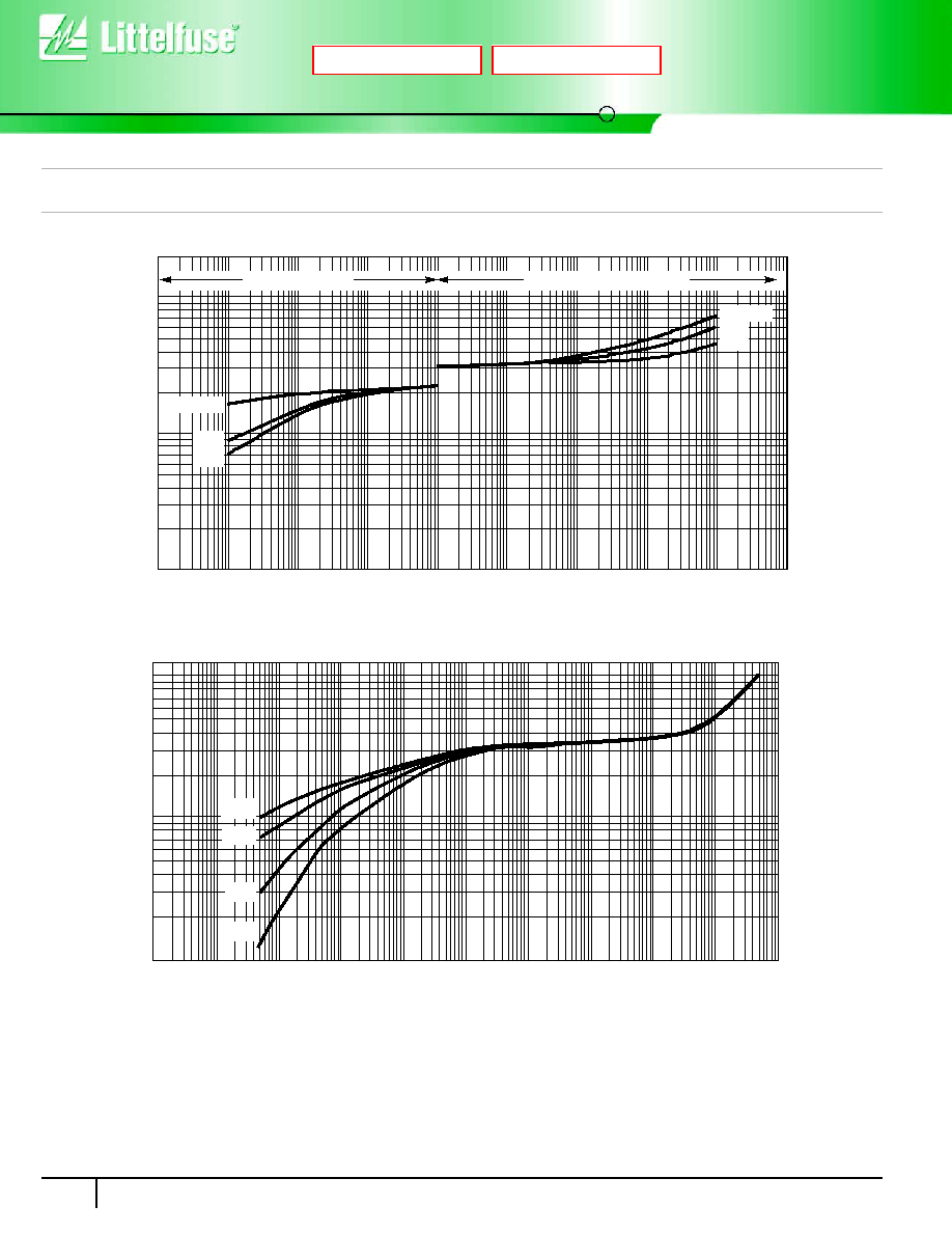
Temperature Effects
In the leakage region of the AUML suppressor, the device characteristics
approaches a linear (ohmic) relationship and shows a temperature
dependent affect. In this region the suppressor is in a high resistance
mode (approaching 10
6
) and appears as a near open-circuit. Leakage
currents at maximum rated voltage are in the microamp range. When
clamping transients at higher currents (at and above the ten milliamp
V-I Characteristics Curves
range), the AUML suppressor approaches a 1-10 characteristic. In
this region the characteristics of the AUML are virtually temperature
independent. Figure 3 shows the typical effect of temperature on the
V-I characteristics of the AUML suppressor.
FIGURE 2. MAXIMUM LEAKAGE CURRENT/CLAMPING VOLTAGE CURVE FOR AUML SERIES AT 25
o
C
FIGURE 3. TYPICAL V-I CHARACTERISTICS OF THE V18AUMLA2220 at -40
o
C, 25
o
C, 85
o
C AND 125
o
C
VO
L
T
AG
E
100
1
1mA
10mA
100mA
1A
10A
100A
CURRENT
100mA
10mA
10
1210/1206
1812
2220
MAXIMUM LEAKAGE
MAXIMUM CLAMPING VOLTAGE
1210/1206
1812
2220
100
10
1
VO
L
T
AG
E
1mA
100mA
10mA
1mA
-40
o
C
25
o
C
85
o
C
10mA
100mA
1A
10A
100A
1000A
CURRENT
125
o
C
Next
Previous
AUML Varistor Series
Surface Mount Varistors
Multilayer Transient Voltage Surge Suppressor
161
w w w . l i t t e l f u s e . c o m
3
SURF
A
CE MOUNT
V
ARIST
ORS
Load Dump Energy Capability
A Load dump transient occurs when the alternator load in the automobile
is abruptly reduced. The worst case scenario of this transient occurs
when the battery is disconnected while operating at full rated load. There
are a number of different load dump specifications in existence in the
automotive industry, with the most common one being that recommend-
ed by the Society of Automotive Engineers, specification #SAE J1113.
Because of the diversity of these load dump specifications Littelfuse
defines the load dump energy capability of the AUML suppressor range
as that energy dissipated by the device itself, independent of the test
circuit setup. The resultant load dump energy handling capability serves
as an excellent figure of merit for the AUML suppressor. Standard load
dump specifications require a device capability of 10 pulses at rated
energy, across a temperature range of -40
o
C to 125
o
C. This capability
requirement is well within the ratings of all of the AUML series (Figure 5).
Further testing on the AUML series has concentrated on extending the
number of load dump pulses, at rated energy, which are applied to the
devices. The reliability information thus generated gives an indication of
the inherent capability of these devices. As an example of device durabil-
ity the 1210 size has been subjected to over 2000 pulses at its rated
energy of 3 joules; the 1812 size has been pulsed over 1000 times at 6
joules and 2220 size has been pulsed at its rated energy of 25 joules
over 300 times. In all cases there has been little or no change in the
device characteristics (Figure 6).
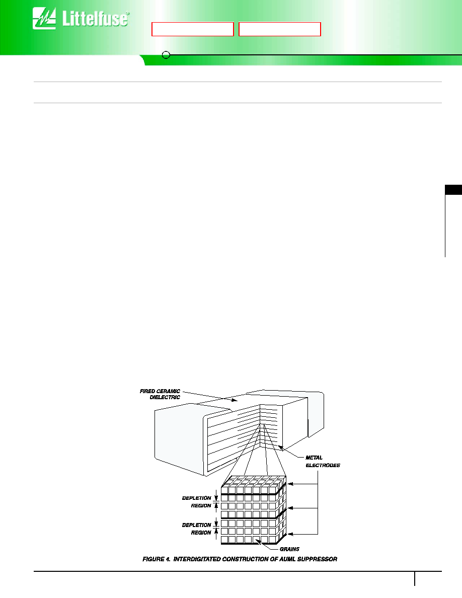
The very high energy absorption capability of the AUML suppressor is
achieved by means of a highly controlled manufacturing process. This
technology ensures that a largevolume of suppressor material, with an
interdigitated layer construction, is available for energy absorption in an
extremely small package. Unlike equivalent rated silicon TVS diodes, the
entire AUML device volume is available to dissipate the load dump energy.
Hence, the peak temperatures generated by the load dump transient are sig-
nificantly lower and evenly dissipated throughout the complete device (Figure
4). This even energy dissipation ensures that there are lower peak tempera-
tures generated at the P-N grain boundaries of the AUML suppressor.
There are a number of different size devices available in the AUML series,
each one with a load dump energy rating, which is size dependent.
Experience has shown that while the effects of a load dump transient is
of real concern, its frequency of occurrence is much less than those of
low energy inductive spikes. Such low energy inductive spikes may be
generated as a result of motors switching on and off, from ESD occur-
rences, fuse blowing, etc. It is essential that the suppression technology
selected also has the capability to suppress such transients. Testing on
the V18AUMLA2220 has shown that after being subjected to a repetitive
energy pulse of 2 joules, over 6000 times, no characteristic changes
have occurred (Figure 7.)
Speed of Response
The clamping action of the AUML suppressor depends on a conduction
mechanism similar to that of other semiconductor devices (i.e. P-N
Junctions). The apparent slow response time often associated with
transient voltage suppressors (Zeners, MOVs) is often due to parasitic
inductance in the package and leads of the device and less dependent
of the basic material (silicon, zinc oxide). Thus, the single most critical
element affecting the response time of any suppressor is its lead induc-
tance. The AUML suppressor is a surface mount device, with no leads or
external packaging, and thus, it has virtually zero inductance. The actual
response time of a AUML surge suppressor is in the 1 to 5 nanosecond
range, more than sufficient for the transients which are likely to be
encountered in an automotive environment.
Next
Previous

Multilayer Transient Voltage Surge Suppressor
AUML Varistor Series
Surface Mount Varistors
162
w w w . l i t t e l f u s e . c o m
Next
Previous