 | –≠–ª–µ–∫—Ç—Ä–æ–Ω–Ω—ã–π –∫–æ–º–ø–æ–Ω–µ–Ω—Ç: V202CA60 | –°–∫–∞—á–∞—Ç—å:  PDF PDF  ZIP ZIP |

114
w w w . l i t t e l f u s e . c o m
Varistor Products
CA Varistor Series
The CA Series of transient surge suppressors are industrial high-energy
disc varistors (MOVs) intended for special applications requiring unique
electrical contact or packaging methods provided by the customer. The
electrode finish of these devices is solderable and can also be used with
pressure contacts. Discs of the same diameter may be stacked.
This series of industrial disc varistors are available in three diameter
sizes of 32, 40, and 60mm, with disc thicknesses ranging from 1.8mm
minimum to 32mm maximum. They offer a wide voltage range of from
250 to 2800 VM(AC)RMS .
For information on soldering considerations, refer to AN8820 update.
"Recommendations for Soldering Terminal Leads to MOV Varistor Discs".
Features
∑ Provided In Disc Form For Unique Packaging By Customer
∑ Solderable Electrode Finish Options
∑ Pressure Contacts and/or Disc Stacking May be Utilized
∑ Standard Disc Sizes 32mm, 40mm, and 60mm Diameter
∑ Available Edge Passivation Insulation
∑ Wide Operating Voltage Range VM(AC)RMS 250V to 2800V
∑ High Peak Pulse Current Range . . . . . . . . . . ITM 20,000A to
70,000A
∑ Very High Energy Capability WTM . . . . . . . . . . . . . . .330J to 10,000J
∑ No Derating Up to 85
o
C Ambient
High Energy Industrial Disc
115
w w w . l i t t e l f u s e . c o m
Varistor Products
2
V
ARIST
OR
PR
ODUCTS
High Energy Industrial Disc
CA Varistor Series
Absolute Maximum Ratings
For ratings of individual members of a series, see Device Ratings and Specifications chart
Continuous:
Steady State Applied Voltage:
AC Voltage Range (VM(AC)RMS) . . . . . . . . . . . . . . . . . . . . . . . . . . . . . . . . . . . . . . . . . . . . . . . . . . . . . . . . . . . . . . . . . . . . . 250 to 2800
V
DC Voltage Range (VM(DC)) . . . . . . . . . . . . . . . . . . . . . . . . . . . . . . . . . . . . . . . . . . . . . . . . . . . . . . . . . . . . . . . . . . . . . . . . . 330 to 3500
V
Transient:
Peak Pulse Current (ITM)
For 8/20µs Current Wave (See Figure 2) . . . . . . . . . . . . . . . . . . . . . . . . . . . . . . . . . . . . . . . . . . . . . . . . . . . . . . . . . . . . . . 20,000 to 70,000
A
Single Pulse Energy Range
For 2ms Current Square Wave (WTM) . . . . . . . . . . . . . . . . . . . . . . . . . . . . . . . . . . . . . . . . . . . . . . . . . . . . . . . . . . . . . . . . . 330 to 10,000
J
Operating Ambient Temperature Range (TA). . . . . . . . . . . . . . . . . . . . . . . . . . . . . . . . . . . . . . . . . . . . . . . . . . . . . . . . . . . . . . . . . 55 to 85
O
C
Storage Temperature Range (TSTG) . . . . . . . . . . . . . . . . . . . . . . . . . . . . . . . . . . . . . . . . . . . . . . . . . . . . . . . . . . . . . . . . . . . . . . . 55 to 85
O
C
Temperature Coefficient (
V) of Clamping Voltage (VC) at Specified Test Current . . . . . . . . . . . . . . . . . . . . . . . . . . . . . . . . . . . . . <0.01
%
O
C
CAUTION: Stresses above those listed in "Absolute Maximum Ratings" may cause permanent damage to the device. This is a stress only rating and operation of the
device at these or any other conditions above those indicated in the operational sections of this specification is not implied.
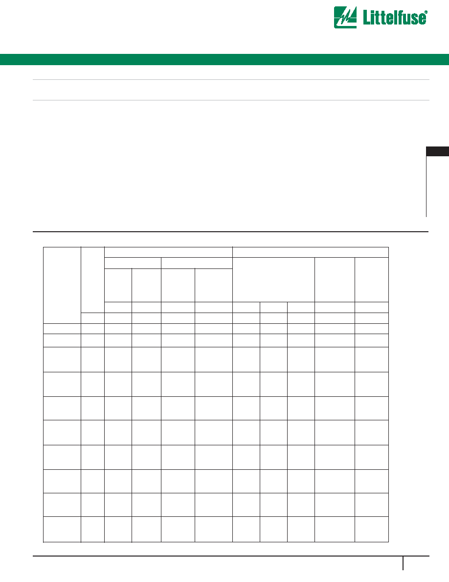
Device Ratings and Specifications
CA SERIES UNITS
MODEL
NUMBER
SIZE
MAXIMUM RATINGS (85
o
C)
SPECIFICATIONS (25
o
C)
CONTINUOUS
TRANSIENT
VARISTOR VOLTAGE AT
1mA DC TEST CURRENT
MAX
CLAMPING
VOLT V
C
AT
200A
CURRENT
(8/20
µ
s)
TYPICAL
CAPACI-
TANCE
V
RMS
V
DC
ENERGY
(2ms)
PEAK
CURRENT
(8/20
µ
s)
V
M(AC)
V
M(DC)
W
TM
I
TM
MIN
V
N(DC)
MAX
V
C
f = 1MHz
(mm)
(V)
(V)
(J)
(A)
(V)
(V)
(V)
(V)
(pF)
V131CA32
32
130
175
200
20000
184
200
228
350
4700
V151CA32
32
150
200
220
20000
212
240
268
410
4000
V251CA32
V251CA40
V251CA60
32
40
60
250
330
330
370
880
20000
40000
50000
354
390
429
680
650
620
2500
5000
10000
V271CA32
V271CA40
V271CA60
32
40
60
275
369
360
400
950
20000
40000
50000
389
430
473
750
730
680
2200
4500
9000
V321CA32
V321CA40
V321CA60
32
40
60
320
420
390
460
1100
20000
40000
50000
462
510
561
850
830
760
1900
3800
7500
V421CA32
V421CA40
V421CA60
32
40
60
420
560
400
600
1500
25000
40000
70000
610
680
748
1200
1130
1060
1500
3000
6000
V481CA32
V481CA40
V481CA60
32
40
60
480
640
450
650
1600
25000
40000
70000
670
750
825
1300
1240
1160
1300
2700
5500
V511CA32
V511CA40
V511CA60
32
40
60
510
675
500
700
1800
25000
40000
70000
735
820
910
1440
1350
1300
1200
2500
5000
V571CA32
V571CA40
V571CA60
32
40
60
575
730
550
770
2100
25000
40000
70000
805
910
1000
1600
1480
1420
1100
2200
4500
V661CA32
V661CA40
V661CA60
32
40
60
660
850
600
900
2300
25000
40000
70000
940
1050
1160
1820
1720
1640
1000
2000
4000

116
w w w . l i t t e l f u s e . c o m
Varistor Products
CA Varistor Series
High Energy Industrial Disc
Power Dissipation Ratings
Should transients occur in rapid succession, the average power
dissipation result is the energy (watt-seconds) per pulse times the
number of pulses per second. The power so developed must be within
the specifications shown on the Device Ratings and Specifications table
for the specific device. Furthermore, the operating values need to be
derated at high temperatures as shown in Figure 1. Because varistors
can only dissipate a relatively small amount of average power they are,
therefore, not suitable for repetitive applications that involve substantial
amounts of average power dissipation.
V751CA32
V751CA40
V751CA60
32
40
60
750
970
700
1050
2600
25000
40000
70000
1080
1200
1320
2050
2000
1880
800
1800
3500
V881CA60
60
880
1150
3200
70000
1290
1500
1650
2340
2700
V112CA60
V142CA60
V172CA60
V202CA60
V242CA60
V282CA60
60
60
60
60
60
60
1100
1400
1700
2000
2400
2800
1400
1750
2150
2500
3000
3500
3800
5000
6000
7500
8600
10000
70000
70000
70000
70000
70000
70000
1620
2020
2500
2970
3510
4230
1800
2200
2700
3300
3900
4700
2060
2550
3030
3630
4290
5170
2940
3600
4300
5200
6200
7400
2200
1800
1500
1200
1000
800
NOTE: Average power dissipation of transients not exceed 1.5W, 2.0W and 2.5W for model 32mm, 40mm and 60mm, respectively.
MODEL
NUMBER
SIZE
MAXIMUM RATINGS (85
o
C)
SPECIFICATIONS (25
o
C)
CONTINUOUS
TRANSIENT
VARISTOR VOLTAGE AT
1mA DC TEST CURRENT
MAX
CLAMPING
VOLT V
C
AT
200A
CURRENT
(8/20
µ
s)
TYPICAL
CAPACI-
TANCE
V
RMS
V
DC
ENERGY
(2ms)
PEAK
CURRENT
(8/20
µ
s)
V
M(AC)
V
M(DC)
W
TM
I
TM
MIN
V
N(DC)
MAX
V
C
f = 1MHz
(mm)
(V)
(V)
(J)
(A)
(V)
(V)
(V)
(V)
(pF)
1. Peak current applies to applications rated up to 115V . Peak Current is 30kA for applications greater than 115V .
2. Peak current applies to applications rated up to 132V . Peak Current is 30kA for applications greater than 132V .
RMS
RMS
RMS
RMS
FIGURE 1. CURRENT, ENERGY AND POWER DERATING
CURVE
100
90
80
70
60
50
40
30
20
10
0
-55
50
60
70
80
90
100 110 120 130 140 150
AMBIENT TEMPERATURE (
o
C)
PERCENT OF RA
TED
V
ALUE
FIGURE 2. PEAK PULSE CURRENT TEST WAVEFORM
100
90
50
10
O
1
T
T
1
T
2
TIME
PERCENT OF PEAK V
ALUE
O
1
= Virtual Origin of Wave
T = Time From 10% to 90% of Peak
T
1
= Virtual Front Time = 1.25 ∑ t
T
2
= Virtual Time to Half Value (Impulse Duration)
Example: For an 8/20
µ
s Current Waveform:
8
µ
s = T
1
= Virtual Front Time
20
µ
s = T
2
= Virtual Time to Half Value
Device Ratings and Specifications
(continued)

117
w w w . l i t t e l f u s e . c o m
Varistor Products
2
V
ARIST
OR
PR
ODUCTS
High Energy Industrial Disc
CA Varistor Series
Transient V-I Characteristics Curves
FIGURE 3. CLAMPING VOLTAGE FOR V131CA32 - C751CA32
FIGURE 4. CLAMPING VOLTAGE FOR V131CA40 - V751CA40
FIGURE 5. CLAMPING VOLTAGE FOR V251CA60 - V881CA60
FIGURE 6. CLAMPING VOLTAGE FOR V112CA60 - V282CA60
200
6,000
5,000
4,000
3,000
2,000
1,000
900
800
600
400
300
10
-3
10
-2
10
-1
10
0
10
1
10
2
10
3
10
4
MAXIMUM PEAK
V
O
L
TS (V)
PEAK AMPERES
V421CA32
V321CA32
V271CA32
V251CA32
10
5
500
700
MAXIMUM CLAMPING VOLTAGE
DISC SIZE 32mm
130 TO 750 V
M(AC)
RATING
V751CA32
V661CA32
V571CA32
V511CA32
V481CA32
T
A
= -55
o
C TO 85
o
C
V151CA32
V131CA32
200
6,000
5,000
4,000
3,000
2,000
1,000
900
800
700
600
500
400
300
10
-2
10
-1
10
0
10
1
10
2
10
3
10
4
10
5
MAXIMUM CLAMPING VOLTAGE
DISC SIZE 40mm
130 TO 750 V
M(AC)
RATING
V421CA40
V151CA40
V751CA40
MAXIMUM PEAK V
O
L
TS (V)
PEAK AMPERES
V131CA40
V321CA40
V271CA40
V251CA40
V511CA40
V481CA40
V571CA40
V661CA40
T
A
= -55
o
C TO 85
o
C
MAX CLAMPING VOLTAGE
DISC SIZE 60mm
250 TO 880V
M(AC)
RATING
T
A
= -55
o
C TO 85
o
C
6,000
5,000
4,000
3,000
2,000
1,000
900
800
700
600
500
400
300
200
10
-2
10
-1
10
0
10
1
10
2
10
3
10
4
10
5
PEAK AMPERES (A)
V881CA60
V751CA60
V661CA60
V571CA60
MAXIMUM PEAK
V
O
L
TS (V)
V511CA60
V481CA60
V421CA60
V321CA60
V271CA60
V251CA60
30,000
20,000
10,000
9,000
8,000
7,000
6,000
5,000
4,000
3,000
2,000
10
-2
10
-1
10
0
10
1
10
2
10
3
10
4
10
5
PEAK AMPERES (A)
MAX PEAK
V
O
L
TS (V)
V282CA60
V242CA60
V202CA60
V172CA60
V142CA60
V112CA60
MAX CLAMPING VOLTAGE
DISC SIZE 60mm
1100 TO 2800V
M(AC)
RATING
T
A
= -55
o
C TO 85
o
C

118
w w w . l i t t e l f u s e . c o m
Varistor Products
CA Varistor Series
High Energy Industrial Disc
Pulse Rating Curves
FIGURE 7. SURGE CURRENT RATING CURVES FOR
V131CA32 - V321CA32
FIGURE 8. SURGE CURRENT RATING CURVES FOR
V421CA32 - V751CA32
FIGURE 9.
SURGE CURRENT RATING CURVES FOR
V131CA40 - V751CA40
FIGURE 10. SURGE CURRENT RATING CURVES FOR
V251CA60 - V321CA60
FIGURE 11. SURGE CURRENT RATING CURVES FOR
V421CA60 - V282CA60
50,000
20,000
10,000
5,000
2,000
1,000
500
200
100
50
20
10
IMPULSE DURATION (
µ
s)
20
100
1,000
10,000
SURGE CURRENT (A)
DISC SIZE 32mm
V131CA32 - V321CA32
1
2
10
10
2
10
5
10
6
INDEFINITE
10
4
10
3
1
2
10
10
2
INDEFINITE
10
6
10
5
50,000
20,000
10,000
5,000
2,000
1,000
500
200
100
50
20
10
IMPULSE DURATION (
µ
s)
20
100
1,000
10,000
SURGE CURRENT (A)
DISC SIZE 32mm
V421CA32 - V751CA32
10
4
10
3
DISC SIZE 40mm
V131CA40 - V751CA40
50,000
20,000
10,000
5,000
2,000
1,000
500
200
100
50
20
10
20
100
1,000
10,000
SURGE CURRENT (A)
IMPULSE DURATION (
µ
s)
10
6
10
2
1
INDEFINITE
10
4
10
3
10
2
10
5
50,000
20,000
10,000
5,000
2,000
1,000
500
200
100
50
20
10
IMPULSE DURATION (
µ
s)
1,000
10,000
10
10
2
10
3
INDEFINITE
10
6
20
100
2
DISC SIZE 60mm
V251CA60 - V321CA60
1
SURGE CURRENT (A)
10
5
10
4
100,000
50,000
20,000
10,000
5,000
2,000
1,000
500
200
100
50
20
10
20
100
1,000
10,000
IMPULSE DURATION (
µ
s)
10
10
2
10
3
10
6
2
1
DISC SIZE 60mm
V421CA60 - V282CA60
INDEFINITE
SURGE CURRENT (A)
10
4
10
5
NOTE: If pulse ratings are exceeded, a shift of VN(DC) (at specified current) of more than ±10% could result. This type of shift, which normally results in a decrease of VN(DC),
may result in the device not meeting the original published specifications, but does not prevent the device from continuing to function, and to provide ample protection.