 | –≠–ª–µ–∫—Ç—Ä–æ–Ω–Ω—ã–π –∫–æ–º–ø–æ–Ω–µ–Ω—Ç: L2330 | –°–∫–∞—á–∞—Ç—å:  PDF PDF  ZIP ZIP |
DEVICES INCORPORATED
Special Arithmetic Functions
1
L2330
Coordinate Transformer
09/27/2001≠LDS.2330-E
u
u
u
u
u
Rectangular-to-Polar or Polar-to-
Rectangular at 50 MHz
u
u
u
u
u Performs Direct Digital Synthesis
(DDS) functions along with PM and
FM Modulation
u
u
u
u
u 24-Bit Polar Phase Angle Accuracy
u
u
u
u
u Replaces Fairchild TMC2330A
u
u
u
u
u 120-pin PQFP
FEATURES
DESCRIPTION
L2330
Coordinate Transformer
DEVICES INCORPORATED
L2330 B
LOCK
D
IAGRAM
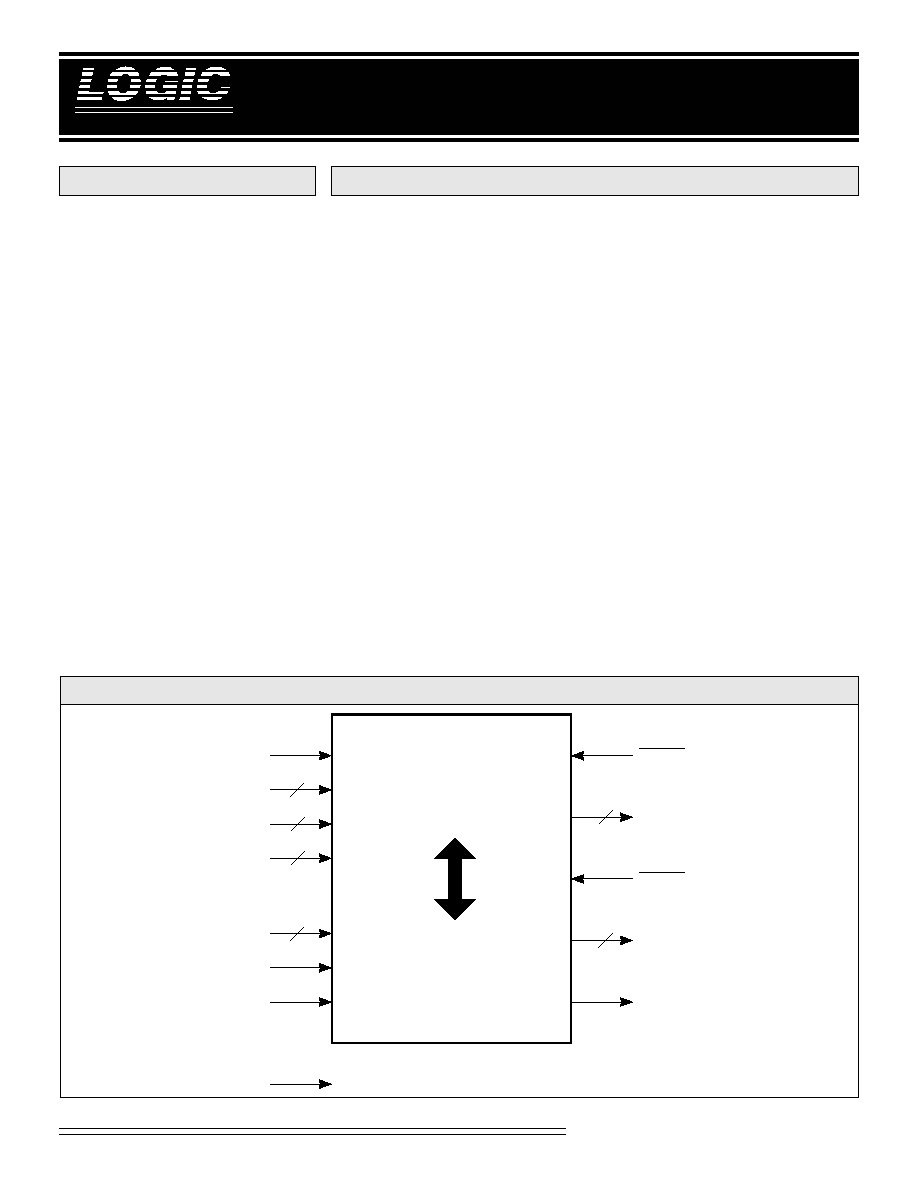
The L2330 is a coordinate transformer
that converts bidirectionally between
Rectangular and Polar coordinates.
When in Rectangular-to-Polar mode,
the L2330 is able to retrieve phase and
magnitude information or backward
map from a rectangular raster display
to a radial data set.
When in Polar-to-Rectangular mode,
the L2330 is able to execute direct
digital waveform synthesis and
modulation. Real-time image-space
conversions are achieved from radi-
ally-generated images, such as RADAR,
SONAR, and ultrasound to raster
display formats.
Functional Description
The L2330 converts bidirectionally
between Rectangular (Cartesian) and
Polar (Phase and Magnitude) coordi-
nates. The user selects the numeric
format. A valid transformed result is
seen at the output after 22 clock cycles
and will continue upon every clock
cycle thereafter.
When in Rectangular-to-Polar mode,
the user inputs a 16-bit Rectangular
coordinate and the output generates a
Polar transformation with 16-bit
magnitude and 16-bit phase. The user
may select the data format to be either
two's complement or sign-and-
magnitude Cartesian data format.
Polar Magnitude data is always in
magnitude format only. Polar Phase
Angle data is modulo 2
so it may be
regarded as either unsigned or two's
complement format.
When in Polar-to-Rectangular mode,
the user inputs 16-bit Polar Magnitude
and 32-bit Phase data and the output
generates a 16-bit Rectangular coordi-
nate. The use may select the data
format to be either two's complement
or sign-and-magnitude Cartesian data
format.
OVF
CLK
POLAR
16
OERX
PYOUT
15-0
16
2
32
ENXR
XRIN
15-0
ENYP
1-0
YPIN
31-0
ACC
1-0
TCXY
RTP
RXOUT
15-0
2
OEPY
16
RECTANGULAR
DEVICES INCORPORATED
L2330
Coordinate Transformer
2
Special Arithmetic Functions
09/27/2001≠LDS.2330-E
ACC
1-0
Configuration
0 0
No accumulation (normal operation)
0 1
PM accumulator path enabled
1 0
FM accumulator path enabled
1 1
Logical OR of PM and FM (Nonsensical)
T
ABLE
2. A
CCUMULATOR
C
ONTROL
SIGNAL DEFINITIONS
Power
V
CC
and GND
+5V power supply. All pins must be
connected.
Clock
CLK -- Master Clock
The rising edge of CLK strobes all
enabled registers.
Inputs
XRIN
15-0
-- x-coordinate/Magnitude
Data Input
XRIN
15-0
is the 16-bit Cartesian
x-coordinate/Polar Magnitude Data
input port. XRIN
15-0
is latched on the
rising edge of CLK.
YPIN
31-0
-- y-coordinate/Phase Angle
Data Input
YPIN
31-0
is the 32-bit Cartesian
y-coordinate/Polar Phase Angle Data
input port. When RTP is HIGH, the input
accumulators should not be used. When
ACC is LOW, the upper 16 bits of YPIN
are the input port and the lower 16 bits
become "don't cares". YPIN
31-0
is latched
on the rising edge of CLK.
Outputs
RXOUT
15-0
-- x-coordinate/Magnitude
Data Output
RXOUT
15-0
is the 16-bit Cartesian
x-coordinate/Polar Magnitude Data
output port. When OERX is HIGH,
RXOUT
15-0
is forced into the high-
impedance state.
PYOUT
15-0
-- y-coordinate/Phase Angle
Data Output
PYOUT
15-0
is the 16-bit Cartesian
y-coordinate/Polar Phase Angle Data
output port. When OEPY is HIGH,
PYOUT
15-0
is forced into the high-
impedance state.
Controls
ENXR -- x-coordinate/Magnitude Data
Input Enable
When ENXR is HIGH, XRIN is latched
into the input register on the rising
edge of clock. When ENXR is LOW,
the value stored in the register is
unchanged.
ENYP
1-0
-- y-coordinate/Phase Angle
Data Input Control
ENYP
1-0
is the 2-bit y-coordinate/
Phase Angle Data Input Control that
determines four modes as shown in
ENYP
1-0
M
C
0 0
Hold
Hold
0 1
Load
Hold
1 0
Hold
Load
1 1
Clear
Load
T
ABLE
1. R
EGISTER
O
PERATION
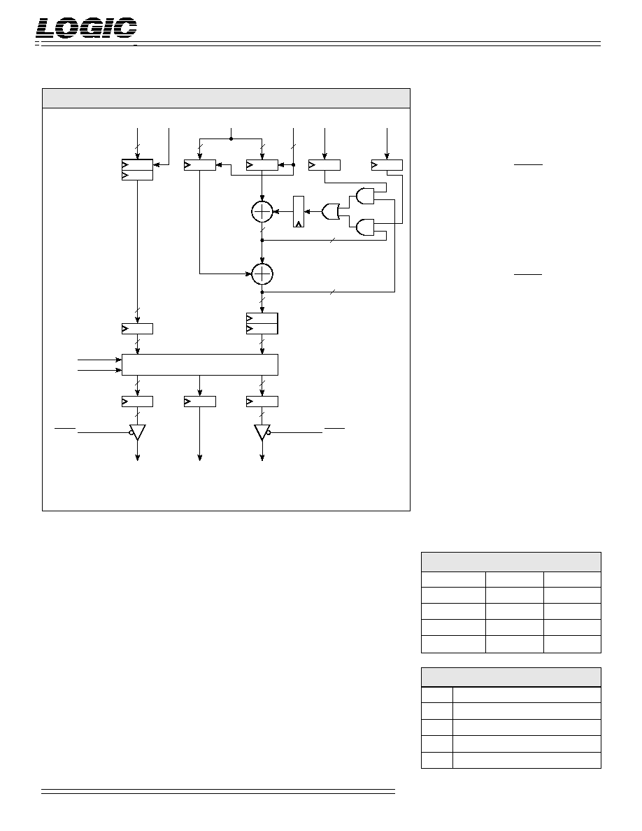
L2330 F
UNCTIONAL
B
LOCK
D
IAGRAM
RXOUT
15-0
PYOUT
15-0
16
16
16
16
16
n
OVF
n
16
16
TRANSFORM
PROCESSOR
OERX
OEPY
TCXY
RTP
32
32
32
XRIN
15-0
32
YPIN
31-0
32
ACC
1
ACC
0
ENXR
ENYP
1-0
2
*
REQUIRES 18 CYCLES TO COMPLETE AND IS FULLY PIPELINED
*
**
**
WHEN RTP IS HIGH 'n' IS 16-BITS, WHEN RTP IS LOW 'n' IS 24-BITS
**
AM
PM
FM
M
C

DEVICES INCORPORATED
Special Arithmetic Functions
3
L2330
Coordinate Transformer
09/27/2001≠LDS.2330-E
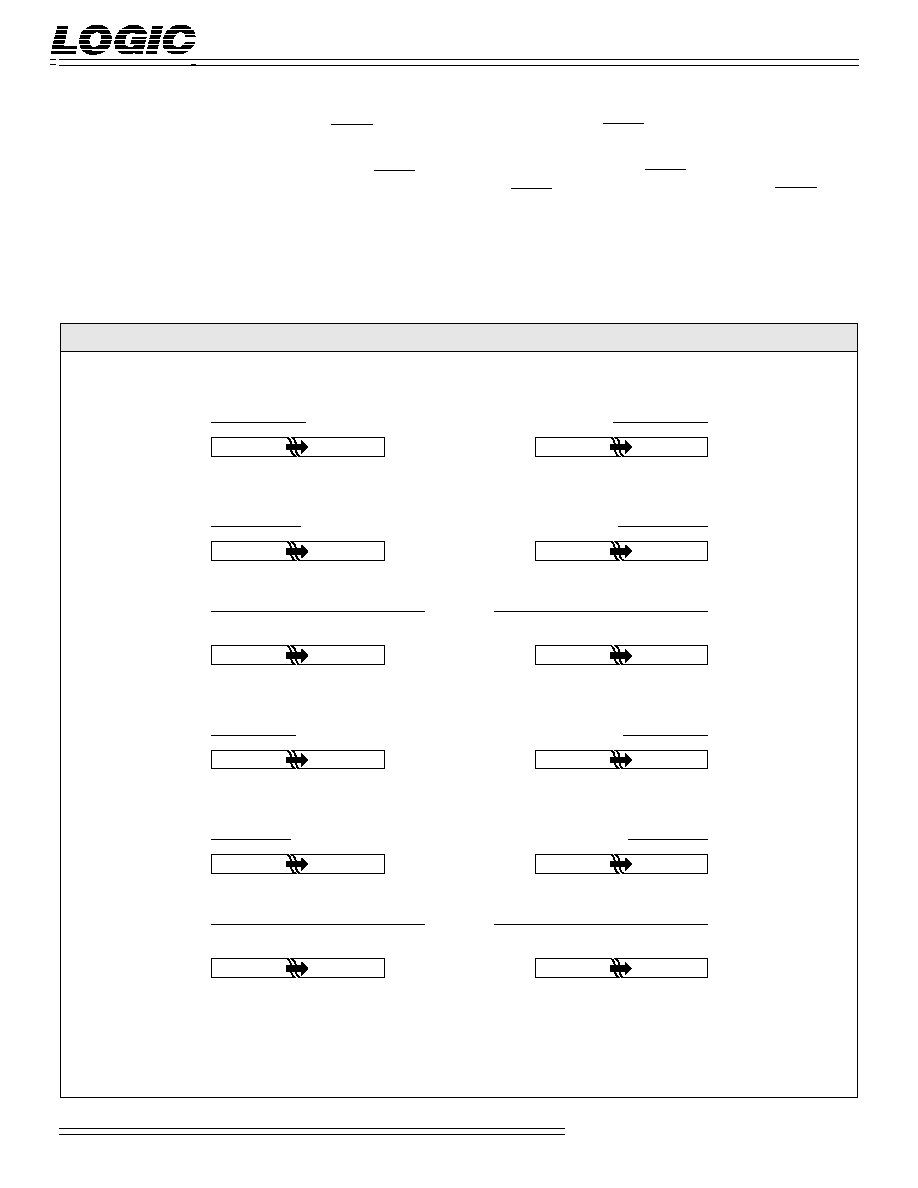
F
IGURE
1
A
.
I
NPUT
F
ORMATS
15 14 13
2
1
0
2
15
2
14
2
13
2
2
2
1
2
0
31 30 29
2
1
0
*±2
0
2
≠1
2
≠2
2
≠29
2
≠30
2
≠31
15 14 13
2
1
0
NS 2
14
2
13
2
2
2
1
2
0
31 30 29
18 17 16
NS 2
14
2
13
2
2
2
1
2
0
Integer Signed Magnitude (RTP = 1, TCXY = 0)
15 14 13
2
1
0
≠2
15
2
14
2
13
2
2
2
1
2
0
31 30 29
18 17 16
≠2
15
2
14
2
13
2
2
2
1
2
0
Integer Two's Complement (RTP = 1, TCXY = 1)
XRIN
YPIN
15 14 13
2
1
0
2
0
2
≠1
2
≠2
2
≠13
2
≠14
2
≠15
31 30 29
2
1
0
*±2
0
2
≠1
2
≠2
2
≠29
2
≠30
2
≠31
Fract. Unsigned Mag./Two's Comp.
15 14 13
2
1
0
NS 2
≠1
2
≠2
2
≠13
2
≠14
2
≠15
31 30 29
18 17 16
NS 2
≠1
2
≠2
2
≠13
2
≠14
2
≠15
Fractional Signed Magnitude (RTP = 1, TCXY = 0)
15 14 13
2
1
0
≠2
0
2
≠1
2
≠2
2
≠13
2
≠14
2
≠15
31 30 29
18 17 16
≠2
0
2
≠1
2
≠2
2
≠13
2
≠14
2
≠15
Fractional Two's Complement (RTP = 1, TCXY = 1)
*±2
0
denotes two's complement sign or highest magnitude bit. Since phase angles are modulo 2
and phase accumulator is modulo 2
32
, this bit may be regarded as ±
.
NS denotes negative sign. (i.e. '1' negates the number)
Fractional Unsigned Magnitude
(RTP = 0)
Fract. Unsigned Mag./Two's Comp.
Integer Unsigned Magnitude
(RTP = 0)
Table 1. `M' is the Modulation
Register and `C' is the Carrier Register
as shown in the Functional Block
Diagram.
RTP -- Rectangular-to-Polar
When RTP is HIGH, Rectangular-to-
Polar conversion mode is selected.
When RTP is LOW, Polar-to-Rectan-
gular conversion mode is selected.
ACC
1-0
-- Accumulator Control
ACC
1-0
is the 2-bit accumulator
control that determines four modes as
shown in Table 2. Changing of the
internal phase Accumulator structure
is very useful when RTP is LOW
allowing for waveform synthesis and
modulation. ACC
1-0
set to `00' is most
commonly used when RTP is HIGH
unless performing backward mapping
from Cartesian to Polar coordinates.
TCXY -- Data Input/Output Format
Select
When TCXY is HIGH, two's comple-
ment format is selected. When TCXY
is LOW, sign-and-magnitude format is
selected.
DEVICES INCORPORATED
L2330
Coordinate Transformer
4
Special Arithmetic Functions
09/27/2001≠LDS.2330-E
F
IGURE
1
B
.
O
UTPUT
F
ORMATS
15 14 13
2
1
0
NS 2
14
2
13
2
2
2
1
2
0
15 14 13
2
1
0
NS 2
14
2
13
2
2
2
1
2
0
Integer Signed Magnitude (RTP = 0, TCXY = 0)
15 14 13
2
1
0
≠2
15
2
14
2
13
2
2
2
1
2
0
15 14 13
2
1
0
≠2
15
2
14
2
13
2
2
2
1
2
0
Integer Two's Complement (RTP = 0, TCXY = 1)
15 14 13
2
1
0
2
15
2
14
2
13
2
2
2
1
2
0
15 14 13
2
1
0
*±2
0
2
≠1
2
≠2
2
≠13
2
≠14
2
≠15
RXOUT
PYOUT
15 14 13
2
1
0
NS 2
≠1
2
≠2
2
≠13
2
≠14
2
≠15
15 14 13
2
1
0
NS 2
≠1
2
≠2
2
≠13
2
≠14
2
≠15
Fractional Signed Magnitude (RTP = 0, TCXY = 0)
15 14 13
2
1
0
≠2
0
2
≠1
2
≠2
2
≠13
2
≠14
2
≠15
15 14 13
2
1
0
≠2
0
2
≠1
2
≠2
2
≠13
2
≠14
2
≠15
Fractional Two's Complement (RTP = 0, TCXY = 1)
15 14 13
2
1
0
2
0
2
≠1
2
≠2
2
≠13
2
≠14
2
≠15
15 14 13
2
1
0
*±2
0
2
≠1
2
≠2
2
≠13
2
≠14
2
≠15
*±2
0
denotes two's complement sign or highest magnitude bit. Since phase angles are modulo 2
and phase accumulator is modulo 2
32
, this bit may be regarded as ±
.
NS denotes negative sign. (i.e. '1' negates the number)
Fract. Unsigned Mag./Two's Comp.
Integer Unsigned Magnitude
(RTP = 1)
Fract. Unsigned Mag./Two's Comp.
Fractional Unsigned Magnitude
(RTP = 1)
OVF -- Overflow Flag
OVF will go HIGH on the clock the
magnitude of either of the current
Cartesian coordinate outputs exceed
the maximum range. OVF will return
LOW on the clock that the Cartesian
output value(s) return within range.
An overflow condition can only occur
when RTP is LOW.
OERX -- x-coordinate/Magnitude Data
Output Enable
When OERX is LOW, RXOUT
15-0
is
enabled for output. When OERX is
HIGH, RXOUT
15-0
is placed in a
high-impedance state.
OEPY -- y-coordinate/Phase Angle Data
Output Enable
When OEPY is LOW, PYOUT
15-0
is
enabled for output. When OEPY is
HIGH, PYOUT
15-0
is placed in a
high-impedance state.
DEVICES INCORPORATED
Special Arithmetic Functions
5
L2330
Coordinate Transformer
09/27/2001≠LDS.2330-E
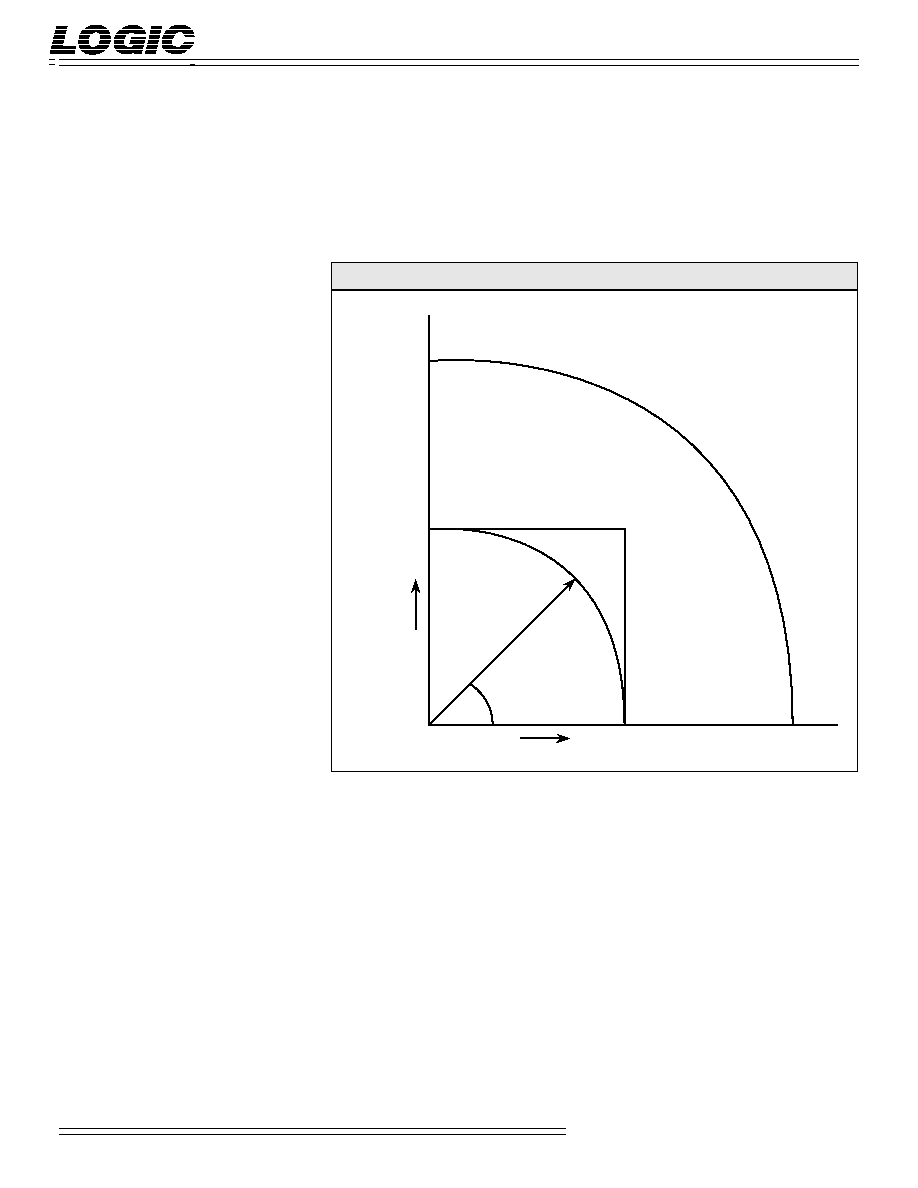
x
y
32767
32767
65535
r
A
B
C
65535
/2
Conversion Ranges
The L2330 supports 16-bit unsigned
radii and 16-bit signed Cartesian
coordinates. Since the 16-bit rectangular
coordinate space does not completely
cover the polar space defined by 16-bit
radii, certain values of "r" will not map
correctly. This condition is indicated by
the overflow (OVF) flag.
In Polar-to-Rectangular conversions, no
overflow occurs for r
32767 (7FFFH).
Overflow will always occur when r >
46341 (B505H). Note that in signed
magnitude mode r = 46340 (B504H)
will also cause an overflow. For 32767
r
46340, overflow may occur depend-
ing on the exact values of r and
.
Figure 2 shows, for the first quadrant,
these three regions: A = no overflow
(correct conversion), B = possible
overflow, C = overflow. The other
quadrants are mapped in a similar
manner.
When in signed magnitude mode, the
overflows on the other three quadrants
are the same as in the first. This occurs
because the signed magnitude number
system is symmetric about zero. For
example, if a given r and angle
cause
an overflow, the same r will cause an
overflow for the angles -
,
+
,
-
.
However, when in two's complement
mode, the overflows aren't quite the
same. This occurs because the two's
F
IGURE
2.
C
ONVERSION
R
ANGES
complement number system is not
symmetric about zero. For example, if
the X or Y component of the input is
≠32768 (8000H), no overflow occurs.
But if the X or Y component of the
input is +32768, overflow does occur.
When converting from Rectangular-to-
Polar, if both inputs are zero the radius
is zero but the angle is not defined.
The L2330 will output 4707H in this
case. Since the angle is not defined for a
zero length vector, this is not an error.