LESHAN RADIO COMPANY, LTD.
LBAT54CLT1≠1/2
1
3
2
DEVICE MARKING
LBAT54CLT1 = KL3
MAXIMUM RATINGS
(T
J
= 125∞C unless otherwise noted)
Rating Symbol Value Unit
Reverse Voltage
V
R
30
Volts
Forward Power Dissipation
P
F
@ T
A
= 25∞C
225
mW
Derate above 25∞C
1.8
mW/∞C
Forward Current(DC)
I
F
200Max
mA
Junction Temperature
T
J
125Max
∞C
Storage Temperature Range
T
stg
≠55 to +150
∞C
ELECTRICAL CHARACTERISTICS
(T
A
= 25∞C unless otherwise noted)
Characteristic
Symbol
Min
Typ
Max
Unit
Reverse Breakdown Voltage (I
R
= 10
µ
A)
V
(BR)R
30
--
--
Volts
Total Capacitance (V
R
= 1.0 V, f = 1.0 MHz)
C
T
--
7.6
10
pF
Reverse Leakage (V
R
= 25 V)
I
R
--
0.5
2.0
µ
Adc
Forward Voltage (I
F
= 0.1 mAdc)
V
F
--
0.22
0.24
Vdc
Forward Voltage (I
F
= 30 mAdc)
V
F
--
0.41
0.5
Vdc
Forward Voltage (I
F
= 100 mAdc)
V
F
--
0.52
0.8
Vdc
Reverse Recovery Time
(I
F
= I
R
= 10 mAdc, I
R(REC)
= 1.0 mAdc, Figure 1)
t
rr
--
--
5.0
ns
Forward Voltage (I
F
= 1.0 mAdc)
V
F
--
0.29
0.32
Vdc
Forward Voltage (I
F
= 10 mAdc)
V
F
--
0.35
0.40
Vdc
Forward Current (DC)
I
F
--
--
200
mAdc
Repetitive Peak Forward Current
I
FRM
--
--
300
mAdc
Non≠Repetitive Peak Forward Current (t < 1.0 s)
I
FSM
--
--
600
mAdc
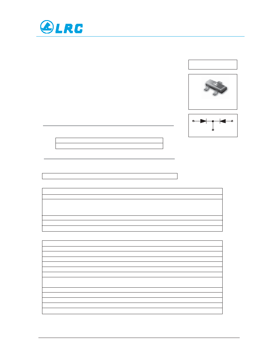
LBAT54CLT1
These Schottky barrier diodes are designed for high speed switch-
ing applications, circuit protection, and voltage clamping. Extremely
low forward voltage reduces conduction loss. Miniature surface mount
package is excellent for hand held and portable applications where
space is limited.
∑ Extremely Fast Switching Speed
∑ Low Forward Voltage -- 0.35 Volts (Typ) @ I
F
= 10 mAdc
ORDERING INFORMATION
Device
Package
Shipping
LBAT54CLT1 SOT≠23 3000/Tape & Reel
Preferred: devices are recommended choices for future use and best overall value.
3
CATHODE
ANODE
1
ANODE
2
Dual Series Schottky
Barrier Diodes
SOT-23
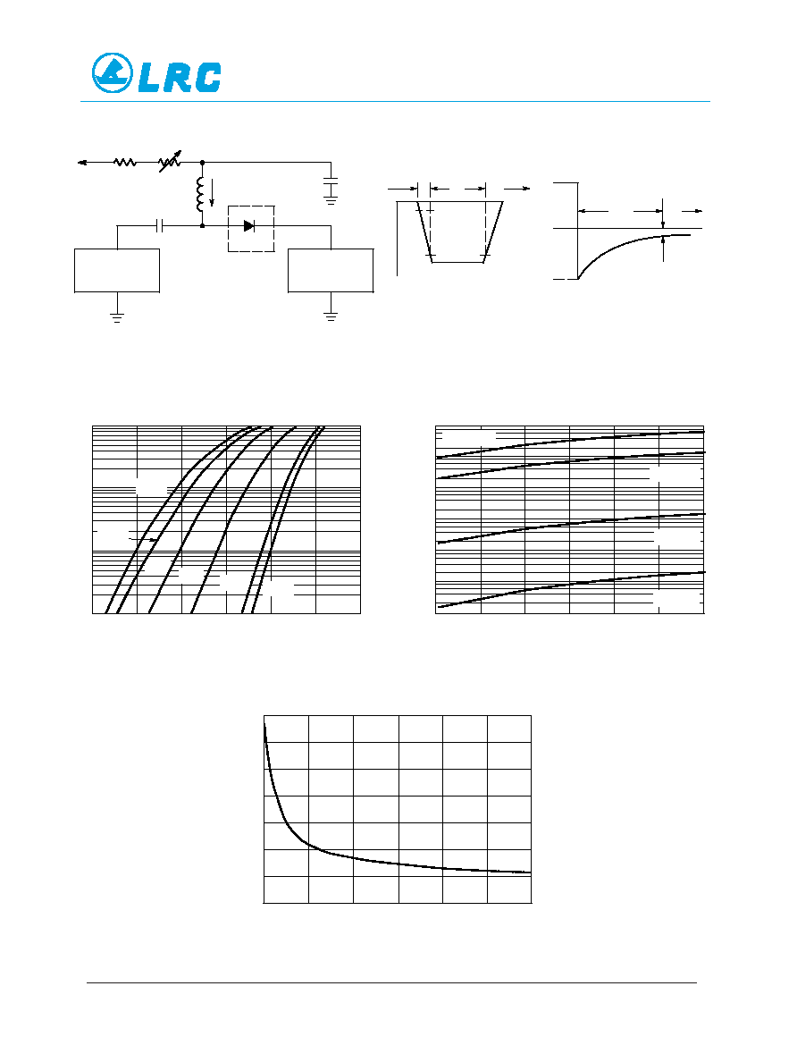
Notes: 1. A 2.0 k
variable resistor adjusted for a Forward Current (IF) of 10 mA.
Notes:
2. Input pulse is adjusted so IR(peak) is equal to 10 mA.
Notes:
3. tp ª trr
+10 V
2 k
820
0.1
µ
F
DUT
VR
100
µ
H
0.1
µ
F
50
OUTPUT
PULSE
GENERATOR
50
INPUT
SAMPLING
OSCILLOSCOPE
tr
tp
t
10%
90%
IF
IR
trr
t
iR(REC) = 1 mA
OUTPUT PULSE
(IF = IR = 10 mA; measured
at iR(REC) = 1 mA)
IF
INPUT SIGNAL
Figure 1. Recovery Time Equivalent Test Circuit
100
0.0
0.1
VF, FORWARD VOLTAGE (VOLTS)
0.2
0.3
0.4
0.5
10
1.0
0.1
85
∞
C
10
0
VR, REVERSE VOLTAGE (VOLTS)
1.0
0.1
0.01
0.001
5
10
15
20
25
14
0
VR, REVERSE VOLTAGE (VOLTS)
12
4
2
0
C
T
, T
OT
AL
CAP
ACIT
ANCE (pF)
5
10
15
30
I F
, FOR
W
ARD
CURRENT
(mA)
Figure 2. Forward Voltage
Figure 3. Leakage Current
Figure 4. Total Capacitance
≠ 40
∞
C
25
∞
C
TA = 150
∞
C
TA = 125
∞
C
TA = 85
∞
C
TA = 25
∞
C
I R
, REVERSE CURRENT
(
µ
A)
0.6
≠ 55
∞
C
1 50
∞
C
1 25
∞
C
100
1000
30
25
20
6
8
10
LESHAN RADIO COMPANY, LTD.
LBAT54CLT1≠2/3
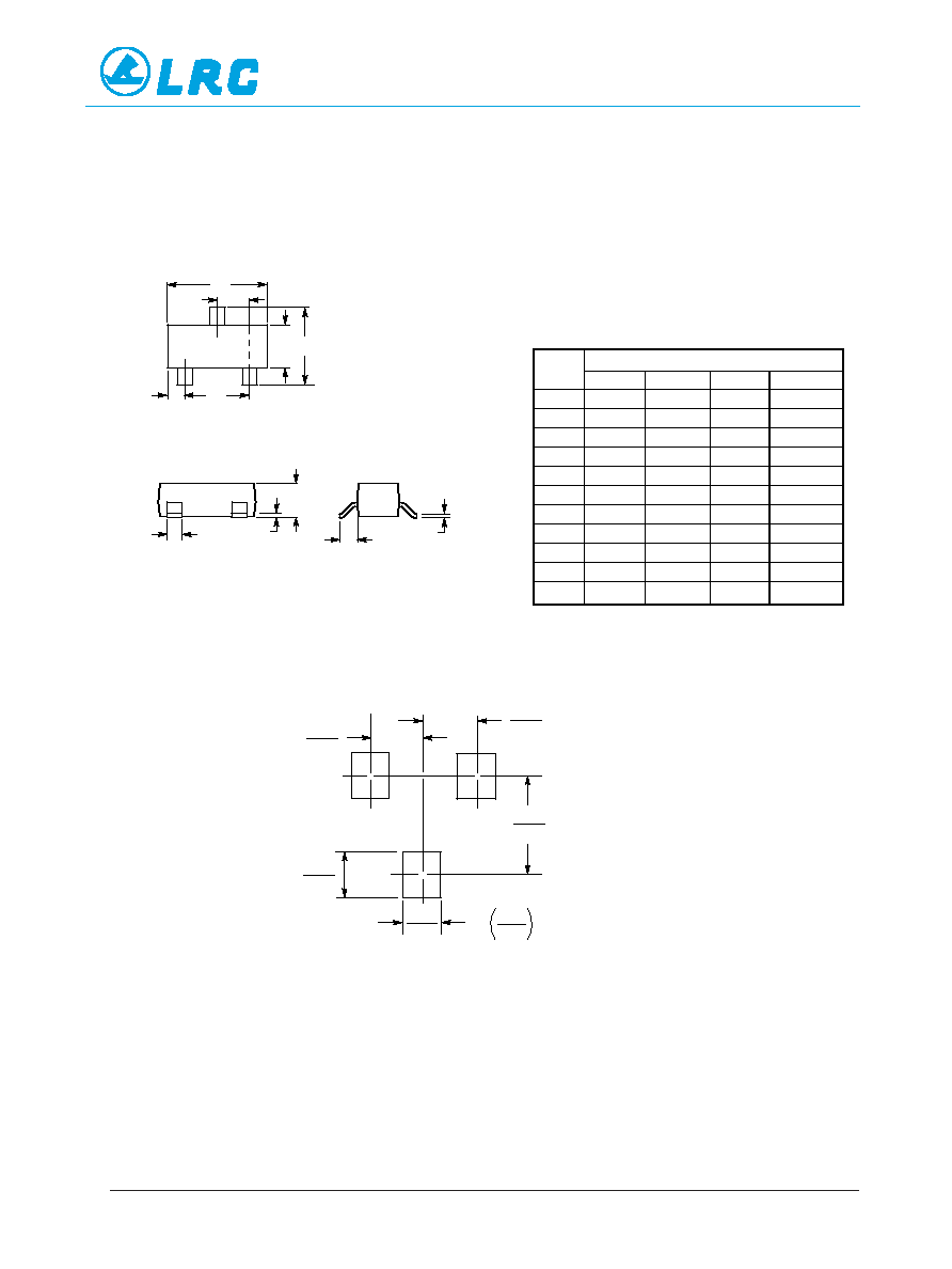
LBAT54CLT1
D
J
K
L
A
C
B S
H
G
V
1
2
mm
inches
0.037
0.95
0.037
0.95
0.079
2.0
0.035
0.9
LESHAN RADIO COMPANY, LTD.
NOTES:
1. DIMENSIONING AND TOLERANCING PER ANSI
Y14.5M, 1982.
2. CONTROLLING DIMENSION: INCH.
INCHES
MILLIMETERS
DIM
MIN
MAX
MIN
MAX
A
0.1102
0.1197
2.80
3.04
B
0.0472
0.0551
1.20
1.40
C
0.0350
0.0440
0.89
1.11
D
0.0150
0.0200
0.37
0.50
G
0.0701
0.0807
1.78
2.04
H
0.0005
0.0040
0.013
0.100
J
0.0034
0.0070
0.085
0.177
K
0.0140
0.0285
0.35
0.69
L
0.0350
0.0401
0.89
1.02
S
0.0830
0.1039
2.10
2.64
V
0.0177
0.0236
0.45
0.60
PIN 1. ANODE
2. ANODE
3. CATHODE
0.03
1
0.
8
SOT-23
3
LBAT54CLT1
LBAT54C-3/3