LESHAN RADIO COMPANY, LTD.
LBAT54LT1-1/3
MAXIMUM RATINGS
(TJ = 125
∞
C unless otherwise noted)
Rating
Symbol
Value
Unit
Reverse Voltage
VR
30
Volts
Forward Power Dissipation
@ TA = 25
∞
C
Derate above 25
∞
C
PD
225
2.0
mW
mW/
∞
C
Forward Current (DC)
IF
200 Max
mA
Junction Temperature
TJ
125 Max
∞
C
Storage Temperature Range
Tstg
≠ 55 to +150
∞
C
ELECTRICAL CHARACTERISTICS
(TA = 25
∞
C unless otherwise noted) (EACH DIODE)
Characteristic
Symbol
Min
Typ
Max
Unit
Reverse Breakdown Voltage (IR = 10
µ
A)
V(BR)R
30
--
--
Volts
Total Capacitance (VR = 1.0 V, f = 1.0 MHz)
CT
--
7.6
10
pF
Reverse Leakage (VR = 25 V)
IR
--
0.5
2.0
µ
Adc
Forward Voltage (IF = 0.1 mAdc)
VF
--
0.22
0.24
Vdc
Forward Voltage (IF = 30 mAdc)
VF
--
0.41
0.5
Vdc
Forward Voltage (IF = 100 mAdc)
VF
--
0.52
1.0
Vdc
Reverse Recovery Time
(IF = IR = 10 mAdc, IR(REC) = 1.0 mAdc) Figure 1
trr
--
--
5.0
ns
Forward Voltage (IF = 1.0 mAdc)
VF
--
0.29
0.32
Vdc
Forward Voltage (IF = 10 mAdc)
VF
--
0.35
0.40
Vdc
Forward Current (DC)
IF
--
--
200
mAdc
Repetitive Peak Forward Current
IFRM
--
--
300
mAdc
Non≠Repetitive Peak Forward Current (t < 1.0 s)
IFSM
--
--
600
mAdc
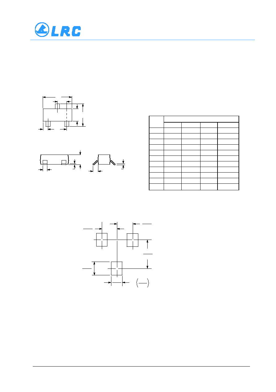
ANODE
1
CATHODE
3
1
3
These Schottky barrier diodes are designed for high speed switching applications,
circuit protection, and voltage clamping. Extremely low forward voltage reduces
conduction loss. Miniature surface mount package is excellent for hand held and
portable applications where space is limited.
∑
Extremely Fast Switching Speed
∑
Low Forward Voltage -- 0.35 Volts (Typ) @ IF = 10 mAdc
Barrier Diodes
Dual Series Schottky
SOT-23
2
LBAT54LT1
∑
Pb-Free package is available
DEVICE MARKING AND ORDERING INFORMATION
Device
Marking
Shipping
LBAT54LT1
J
V3
3000/Tape&Reel
LBAT54LT1G
(Pb-Free)
J
V3
3000/Tape&Reel
LESHAN RADIO COMPANY, LTD.
LBAT54LT1-2/3
LBAT54LT1
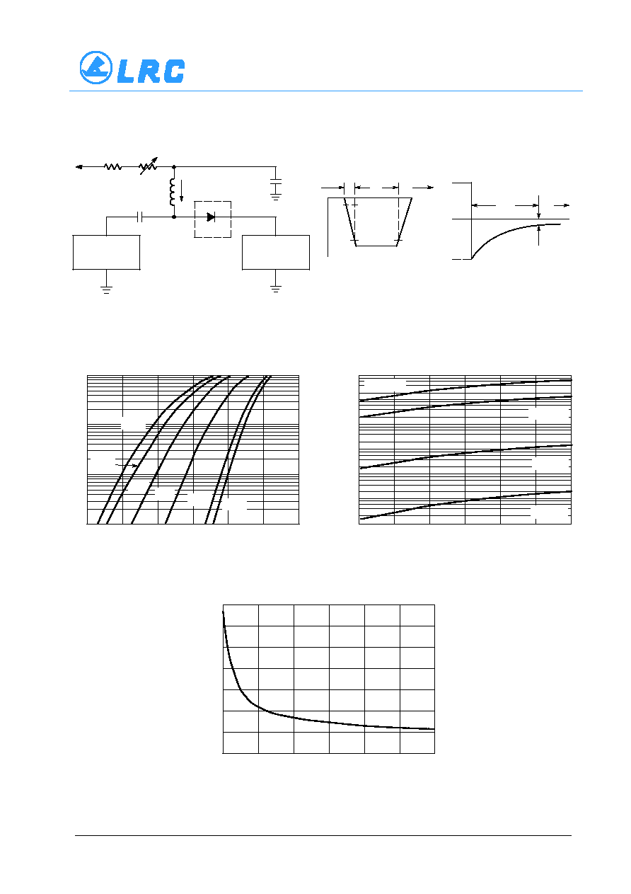
Notes: 1. A 2.0 k
variable resistor adjusted for a Forward Current (IF) of 10 mA.
Notes:
2. Input pulse is adjusted so IR(peak) is equal to 10 mA.
Notes:
3. tp ª trr
+10 V
2 k
820
0.1
µ
F
DUT
VR
100
µ
H
0.1
µ
F
50
OUTPUT
PULSE
GENERATOR
50
INPUT
SAMPLING
OSCILLOSCOPE
tr
tp
t
10%
90%
IF
IR
trr
t
iR(REC) = 1 mA
OUTPUT PULSE
(IF = IR = 10 mA; measured
at iR(REC) = 1 mA)
IF
INPUT SIGNAL
Figure 1. Recovery Time Equivalent Test Circuit
100
0.0
0.1
VF, FORWARD VOLTAGE (VOLTS)
0.2
0.3
0.4
0.5
10
1.0
0.1
85
∞
C
10
0
VR, REVERSE VOLTAGE (VOLTS)
1.0
0.1
0.01
0.001
5
10
15
20
25
14
0
VR, REVERSE VOLTAGE (VOLTS)
12
4
2
0
C
T
, T
OT
AL
CAP
ACIT
ANCE (pF)
5
10
15
30
I F
, FOR
W
ARD
CURRENT
(mA)
Figure 2. Forward Voltage
Figure 3. Leakage Current
Figure 4. Total Capacitance
≠ 40
∞
C
25
∞
C
TA = 150
∞
C
TA = 125
∞
C
TA = 85
∞
C
TA = 25
∞
C
I R
, REVERSE CURRENT
(
µ
A)
0.6
≠ 55
∞
C
1 50
∞
C
1 25
∞
C
100
1000
30
25
20
6
8
10