PROXIMITY/TOUCH CONTROL HALOGEN LAMP DIMMER
DESCRIPTION:
LS7232NT is a CMOS integrated circuit designed for brightness
control of incandescent lamps or tranformer coupled low voltage
halogen lamps. The brightness is controlled by controlling the fir-
ing angle of a triac in series with the lamp and triggered by the
LS7232NT. A Phase-Locked-Loop keeps the LS7232NT phase
pointer locked in phase with the line voltage.
A unique optical user interface provides for a smooth control of
the lamp intensity without the need for touching any sensor
plate. A mechanical switch interface for dimming control is also
provided which can be used for a remote touch plate. The IC in-
cludes features to address problems associated with inductive
loads such as transformers in low voltage halogen lamp applica-
tion. The voltage to current phase lag resulting from the in-
ductance may prevent the triac from shutting off at AC zero
crossover and/or prevent the triac from maintaining conduction
following the removal of the gate trigger. The inductive load
problems are addressed by the LS7232NT as follows:
1. Compensation for delayed triac cut-off.
When trigger pulse is due to occur at a conduction angle
which coincides with the on-state of the triac, the trigger
pulse is delayed until the triac has turned off. This elim-
inates the underlying cause of half-waving.
2. Compensation for delayed triac turn-on.
At the set conduction angle, a triac trigger pulse of 130.2µs
(60Hz) is issued by the dimmer IC. If the triac fails to fire, a
second trigger pulse of 260.4µs width is issued 1 ms later
as a second attempt to fire the triac during the same half-
cycle.
3. Safety-Shutdown.
If the frequency of occurrences of the delayed cut-off and
the delayed turn-on exceeds a preset threshold, a shut-
down is initiated by turning off the triac trigger pulses. The
safety-shutdown threshold value is accumulated in a 4-bit
Up/Down counter. The count increments for every oc-
currence of delayed cut-off or delayed turn-on and decre-
ments once every 8 SYNC pulses (AC line cycles). The
count will not decrement below zero. If the count reaches
15, the safety-shut-down is effected.
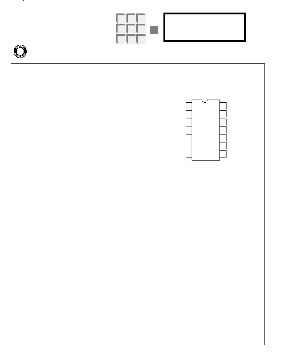
PIN ASSIGNMENT - TOP VIEW
1
2
3
4
5
6
7
8
9
1 0
1 1
1 2
1 3
1 4
LS7232NT
CAP
SYNC
ANODE
CATHODE
PHOTOUT
S E N S
REMOTE
V
DD
( + V )
M2
M1
RC
LEDO
T R I G /
V s s ( - V )
FIGURE 1
The LS7232NT can be configured in 7 different modes of dim-
ming and timing off functions selected by two 3-state mode
pins.
INPUT/OUTPUT DESCRIPTION:
CAP (Pin 1)
PLL filter capacitor input. A 0.02µF capacitor is required at this
input for the optimal operation of the PLL.
SYNC (Pin 2)
The phase pointer for the triac trigger signal is synchronized
with the 50Hz/60Hz AC voltage applied at the SYNC input by
the internal PLL. The triac On/Off status information is also de-
rived from this input.
ANODE (Pin 3) CATHODE (Pin 4) and PHOTOUT (Pin 5)
These three pins constitute the input/outputs of a trans-
conductance and voltage amplifier pair (See Fig. 6) for con-
verting the current from a photo-diode to a voltage stimulus for
application at the SENS input. The photo-signal is used in lieu
of a touch plate for a touchless dimmer system. The output at
PHOTOUT is governed by the following equation:
V
OUT
= V
DD
/2 + 2I
D
R
f
Where V
DD
= Supply Voltage
I
D
= Current in Photo-diode connected between
ANODE and CATHODE
R
f
= Feedback resistance between PHOTOUT
and CATHODE
A potentiometer is used for R
f
for controlling the sensitivity of
the photo-amplifier system.
7232NT-012703-1
January 2003
FEATURES:
∑ Control of incandescent and transformer-coupled
low voltage halogen lamps.
∑ No-Touch lamp control through optical sensing
∑ PLL synchronization of AC for wall switch application.
∑ Extension input for remote control
∑ Safety-shutdown for transformer malfunction.
∑ Pin-selectable operating modes
∑ Single 5V power supply
∑ 50Hz/60Hz AC line frequency
∑ LS7232NT (DIP); LS7232NT-S (SOIC) - See Figure 1
LSI/CSI
LSI Computer Systems, Inc. 1235 Walt Whitman Road, Melville, NY 11747 (631) 271-0400 FAX (631) 271-0405
LS7232NT
UL
Æ
A3800
SENS (Pin 6)
A positive signal applied at the SENS input controls the turn-on,
turn-off and dimming function of the LS7232NT. The SENS in-
put is designed to operate with very low levels of signal, so that
it can be directly interfaced with the photoamplifier output. Sig-
nal at the SENS input is amplified with a gain of 30. If a photo-
sensor is not to be used, the SENS input can easily be adapted
to a touch plate.
Signals at the SENS input are classified as SHORT touch and
LONG touch. Signals between 50ms and 350ms constitute a
SHORT touch, whereas signals longer than 350ms constitute a
LONG touch. The functions of these two types of touches are
explained in the mode description section.
SENS input has an internal pull-down resistor of 10k
.
REMOTE (Pin 7)
For performing dimming operation from remote sites or through
wire extensions, the REMOTE input is used. This input is sam-
pled twice during both negative and positive half cycles of the
AC, rendering it more immune to noise and hence more suited
for carrying signals over extension wires.
Vss (Pin 8)
Supply voltage, negative terminal
.
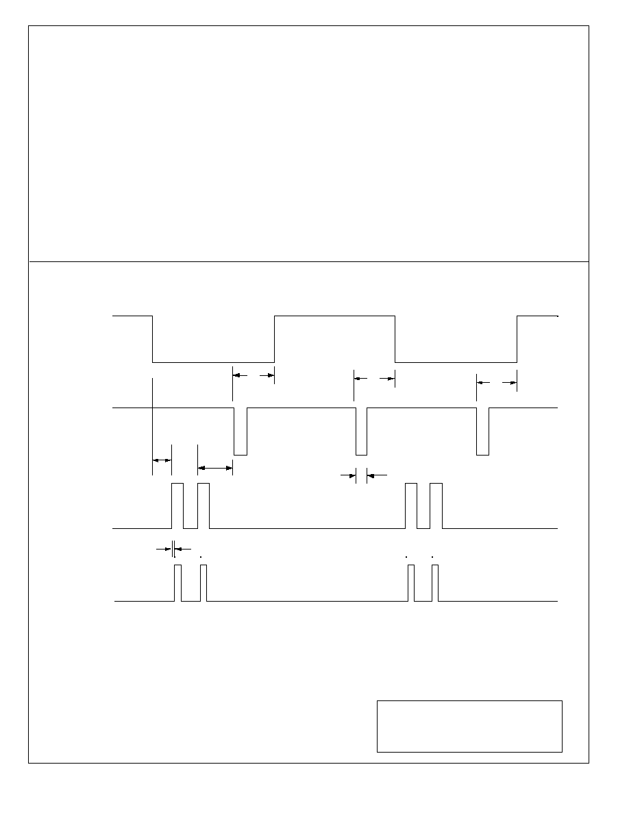
T
RIG/ (Pin 9)
Trigger ouput for driving the gate of a triac. A negative pulse of
nominally 130.2µs duration is generated at this output which
can be varied between 19.7∞ and 119.5∞ from the zero-
crossover of the AC during every half cycle. The control of con-
duction angle of the TRIG/ output is effected by Short and Long
touches at the SENSE and REMOTE inputs.
LEDO (Pin 10)
A positive pulse of 32µs is generated at this output during every
negative half-cycle of the AC. If the TRIG/ output is Off, the
LEDO is generated nominally 911µs after the AC zero-
crossover in the negative half-cycles. If the TRIG/ output is on,
the LEDO tracks the TRIG/ output signal and is generated
170µs ahead of the TRIG/ output, during every negative half-
cycle of the AC.
The LEDO is used to drive an infra-red LED. When a reflecting
object, such as a human hand, is brought close to the infrared
LED, the light is reflected back to the Photo-diode, which is
mounted in physical proximity to the infra-red LED. The change
of intensity of the received light by the photo-diode results in a
change of the photo-diode current which in turn is amplified by
the transconductance amplifier as described in the ANODE
input section.
RC (Pin 11)
A resistor-capacitor pair connected externally to the RC input
constitutes the timing element for the delay generation in Modes
4, 5, 6, and 7. The delay is given by the expression,
= 63RC.
M1 and M2 (Pin 12 and Pin 13)
Each of these inputs are 3-state inputs, namely Low (L), High
(H) and Float (F). The logic levels of these two inputs together,
configures the operating modes of the LS7232NT according to
Table 1.
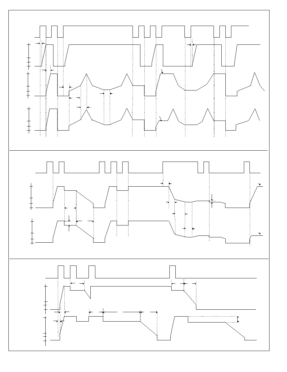
MODE DESCRIPTIONS:
See Figures 2, 3, and 4 for further explanations.
MODE 1 - Touch causes the TRIG/ output to toggle between
Off and Max. The Off to Max transition slews in 350ms(tr). Long
and Short Touch operate in identical manner. Leading edge
touch sense (change occurs upon initiation of touch)
7232NT-012703-2
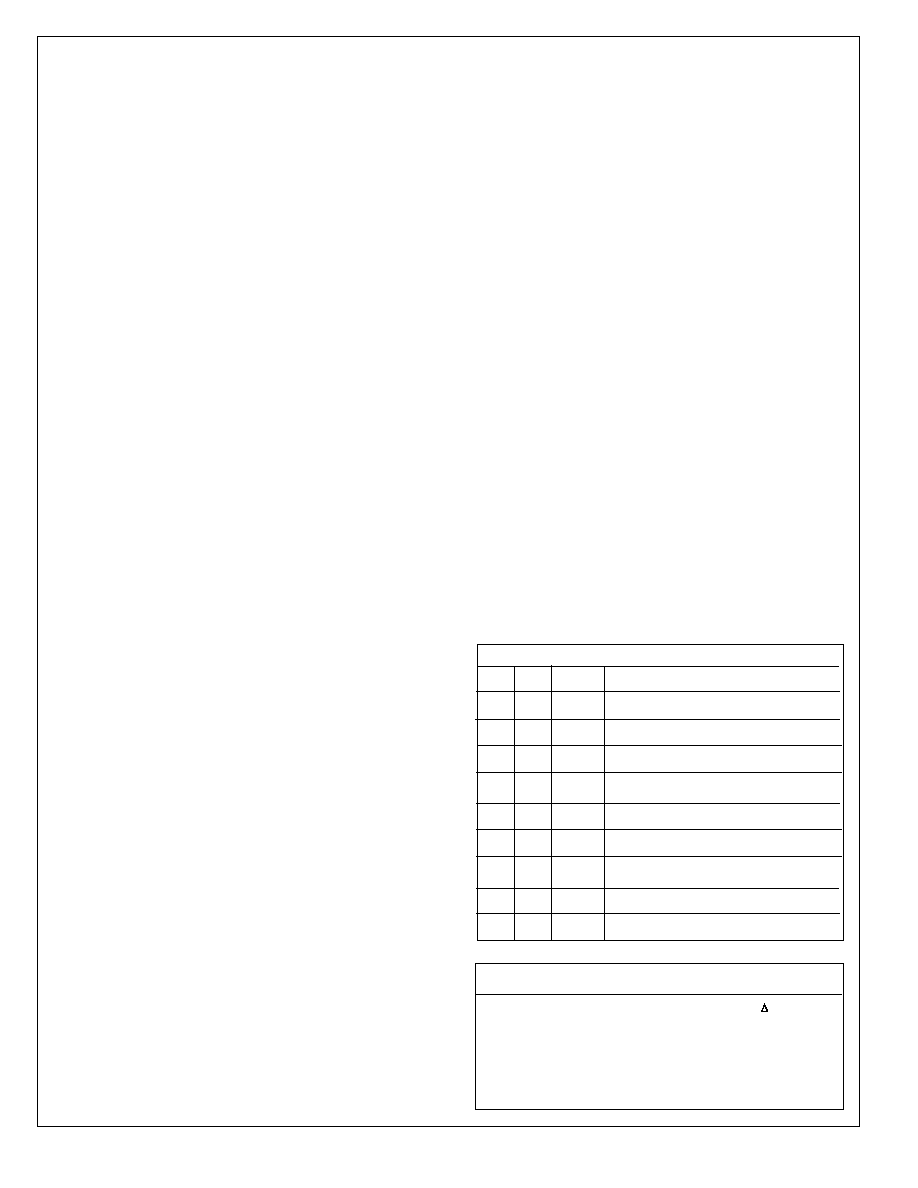
TABLE 1. OPERATING MODES
M1 M2 MODE DESCRIPTION
L
L
1
ON - OFF
L
F
2
ON - OFF - DIMMER
L
H
3
ON - OFF - MEMORY - DIMMER
F
F
4
ON - DELAYED_OFF - DIMMER
F
H
5
ON - DELAYED_OFF - MEMORY-DIMMER
F
L
6
ON - DELAYED_OFF
H
L
7
ON - AUTO_OFF_TIMER
H
F
X
NOT ALLOWED
H
H
X
NOT ALLOWED
MODE 2 - Same effect for Short Touch as in Mode 1. Long Touch
causes the output to sweep between conduction angles of 38∞ (Min)
and 155∞ (Max) in increments of 1.4∞. The sweep direction auto-
matically reverses at Min and Max. Sweep direction also reverses for
every Long Touch. Trailing edge sensing for Short Touch. (Change
occurs upon removal of touch.)
MODE 3 - Same as Mode 2 except for Short Touch the output
toggles between Off and Memory. Memory is updated with the long
touch.
MODE 4 - Same as Mode 2 except the On to Off operation with
Short Touch is delayed. At the termination of the Short Touch the out-
put level instantaneously drops by an amount of
ÿ to indicate the
beginning of the turn-off delay, t
RC
. At the end of the delay, the output
slews off at a rate of 56∞/s. The delay t
RC
is controlled by a resistor-
capacitor pair at the RC (Pin 11) input, according to the following
expression:
t
RC
= 63RC
The magnitude of
ÿ is dependent on the pre-touch intensity from
where the turn-off delay is initiated and can have one of the values in
Table 2 (See Fig. 2 and 3).
MODE 5 - Same as Mode 4, except a Short Touch in the Off state
switches the output to memory.
MODE 6 - Same as Mode 4, except that there is no dimming func-
tion in Mode 6. Both Short and Long touches operate as Short Touch
(leading edge touch sense).
MODE 7 - Output switches from Off to Max with either Short or Long
Touch (leading edge touch sense). After a delay of t
RC
= 63RC (See
description of Mode 4) the output drops by an angle
ÿ according to
Table 2. After another fixed delay of 10sec (tf) the output slews off in
2sec (td7) at the rate of 56∞/sec. A touch during t
RC
time out has no
effect. A touch during tf and td7 timeouts aborts the timeout and
restores output to Max.
TABLE 2. BRIGHTNESS DROP AT DELAY START,
ÿ
PRE-TOUCH CONDUCTION ANGLE ÿ
155∞ to 130∞
-35∞
129∞ to 115∞
-25∞
114∞ to 95∞
-20∞
94∞ to 45∞
-10∞
44∞ to 38∞
Instantaneous Off

ABSOLUTE MAXIMUM RATINGS:
PARAMETER SYMBOL VALUE UNIT
DC Supply Voltage
V
DD
- V
SS
+7
V
Any Input Voltage
V
IN
Vss - 0.3 to V
DD
+ 0.3
V
Operating Temperature
T
A
0 to +90
∞C
Storage Temperature
T
STG
-65 to +150
∞C
7232NT-012703-3
DC ELECTRICAL CHARACTERISTICS: (T
A
= 25∞C, V
DD
= +5V, All voltages referenced to Vss)
PARAMETER SYMBOL
MIN
TYP MAX UNIT CONDITION
Supply Voltage V
DD
4.5
5.0
5.5
V -
Supply Current
I
DD
≠
400
500
µA Output unloaded
Input Logic Levels:
SYNC Lo
-
-
≠
2.0
V -
SYNC Hi
-
3.0
≠
-
V -
REMOTE Lo
-
-
≠
1.5
V -
REMOTE Hi
-
3.5
≠
-
V -
SENS Lo
-
-
≠
50
mV -
SENS Hi
-
150
≠
-
mV -
RC Lo
-
-
-
2.0
V -
RC Hi
-
3.0
-
-
V -
Output Current:
LEDO Sink
-
-1.0
-1.5
-
mA Vo = 0.5V
LEDO Source
-
10.0
14.0
-
mA Vo = 2.2V
TRIG/ Sink
-
-35.0
-
-
mA Vo = 3.5V
RC Sink
-
-3.0
-4.0
-
mA Vo = 2.0V
TRANSIENT CHARACTERISTICS (See Figures 2, 3, 4 and 5):
All time parameters are based on 60Hz SYNC. For 50Hz a multiplication factor of 1.2 should be used.
PARAMETER
SYMBOL
MIN TYP MAX
UNIT
CONDITION
SYNC Frequency
fs
40
-
70
Hz -
Short Touch
ts
50
-
350
ms -
Long Touch
t
L
350
-
infinite
ms -
TRIG/ Pulse Width
T
W
-
130.2
-
µs -
Conduction Range
ÿ
38
-
155
deg -
ÿ increments
ÿs
-
1.4
-
deg ÿ = 84ÿs
Short Touch:
Off to Max (Slew Time)
t
1
-
350
-
ms -
Long Touch:
Ramp Time between 38∞ & 59∞
t
2
-
1.0
-
sec -
Ramp Time between 59∞ & 155∞
t
3
-
2.27
-
sec -
Dwell at min
t
4
-
500
-
ms -