 | –≠–ª–µ–∫—Ç—Ä–æ–Ω–Ω—ã–π –∫–æ–º–ø–æ–Ω–µ–Ω—Ç: LS7631 | –°–∫–∞—á–∞—Ç—å:  PDF PDF  ZIP ZIP |

TOUCH CONTROL HALOGEN LAMP DIMMER
1
2
3
4
5
6
7
8
LS7631
LS7632
V
DD
(+V)
MODE
CAP
SYNC
TRIG
V
SS
(-V)
EXT
S E N S
FIGURE 1
LSI
FEATURES:
∑ Touch or pushbutton control of incandescent lamps
and transformer-coupled halogen lamps
∑ Transformer can be Magnetic or Electronic
∑ Direct replacement for P/N SLB 0587
∑ Automatic safety shutdown
∑ PLL synchronization allows use as a Wall Switch
∑ Three operating modes
∑ Extension input for remote activation
∑ 50Hz/60Hz AC line frequency
∑ +5V Power Supply (V
DD
- V
SS
)
∑ LS7631, LS7632 (DIP); LS7631-S, LS7632-S (SOIC)
APPLICATIONS:
Electronic dimmers for wall switch control of ceiling mounted
lighting, foot switch control of large floor lamps and hand switch
control of table lamps.
BACKGROUND AND GENERAL DESCRIPTION:
A typical electronic dimmer may not operate properly with the in-
ductive load encountered when driving a transformer-coupled
low-voltage halogen lamp. The inductive load can cause a
phenomenon called half-waving, wherein the triac fires in al-
ternate half-cycles only, which may lead to the thermal de-
struction of the load transformer. The problems encountered in
driving an inductive load are addressed by the LS7631/LS7632
CMOS ICs as follows:
1. Compensation for delayed triac cut-off.
When a trigger pulse is due to occur at a conduction
angle which coincides with the on-state of the triac, the
trigger pulse is delayed until the triac has turned off. This
eliminates the underlying cause of half-waving.
.
2. Compensation for delayed triac turn-on.
At the set conduction angle, a triac trigger pulse of
130.2µs (60 Hz) is issued by the IC. If the triac fails to fire, a
second trigger pulse of 260.4µs width is issued 1ms later as
a second attempt to fire the triac during the same half-cycle.
3. Safety-shutdown.
If the frequency of occurrences of the delayed cut-off and
delayed turn-on exceeds a preset threshold, a shutdown is
initiated by turning off the triac trigger pulses. The safety-
shutdown threshold value is accumulated in a 4-bit Up/Down
counter. The count increments for every occurrence of
delayed cut-off or delayed turn-on and decrements once
every 8 SYNC pulses (AC line cycles). The counter will not
decrement below zero. If the count reaches 15, the safety-
shut-down is effected.
INPUT/OUTPUT DESCRIPTION:
V
DD
(Pin 1) Supply voltage positive terminal.
Vss (Pin 7) Supply voltage negative terminal.
MODE (Pin 2) - See Table 1
Both LS7631 and LS7632 can operate in 3 different modes.
The 3-state MODE input selects the operating modes:
Vss = Mode 0; Float = Mode 1; V
DD
= Mode 2
CAP (Pin 3) - PLL filter capacitor input. See Figure 6.
SYNC (Pin 4) - See Figure 6
The AC line frequency is applied to this input. All internal timings
are synchronized to the AC phase through a PLL circuit. The
Load On/Off status information is also derived from this input.
SENS (Pin 5) - See Table 1
A Logic 0 applied to this input alters the TRIG output either by
turning it on, turning it off or by changing its conduction angle.
Specifically which action takes place is dependent on the type of
activation of the SENS input, namely SHORT or LONG touch
and the prior state of TRIG output.
EXT (Pin 6)
Same functionality as the SENS input, except that a Logic 1 is the
active level at this input. EXT input is intended to be operated
from a remote site with long cable connection, when noise can be
expected. The sampling method used at this input makes it less
sensitive to noise.
TRIG (Pin 8)
The TRIG output is a low level pulse occurring once every half-
cycle of the AC and is intended to drive the gate of a triac in se-
ries with the load. The conduction angle, ¯, of the TRIG pulse can
be varied by means of LONG and SHORT touches at either the
SENS or the EXT input.
November 2002
7631/7632-112002-1
LSI/CSI
LSI Computer Systems, Inc. 1235 Walt Whitman Road, Melville, NY 11747 (631) 271-0400 FAX (631) 271-0405
LS7631/7632
UL
Æ
A3800
PIN ASSIGNMENT - TOP VIEW

The functional differences between LS7631 and LS7632 are:
LS7631 - When a LONG touch is applied, the dimming direction auto-
matically reverses whenever maximum or minimum conduction an-
gles are reached.
LS7632 - When a LONG touch is applied, the dimming stops when-
ever maximum or minimum conduction angles are reached. In order to
change dimming levels from maximum or minimum, LONG touch must
be removed and reapplied.The purpose of this feature is to allow the
user to positively locate maximum and minimum conduction angles.
TABLE 1
MODE SHORT TOUCH LONG TOUCH DIMMING
REVERSAL
PRE-TOUCH ÿ POST-TOUCH ÿ PRE-TOUCH ÿ POST-TOUCH ÿ
(Note 5)
OFF
MAX(Note 1)
OFF/MIN
Varies up from MIN
N/A
0
ON
OFF
MAX
Varies down from MAX
N/A
INTERMEDIATE
Varies from INTERMEDIATE
NO
OFF
MEMORY
OFF
Varies from memory (Notes 2, 3,4)
YES
1
(Notes 2, 3)
MIN
Varies up from MIN
N/A
ON
OFF
MAX
Varies down from MAX
N/A
INTERMEDIATE
Varies from INTERMEDIATE
YES
OFF
MAX (Note 1)
OFF/MIN
Varies up from MIN
N/A
2
ON
OFF
MAX
Varies down from MAX
N/A
INTERMEDIATE
Varies from INTERMEDIATE
YES
Note 1:
A soft turn-on is produced by slewing up the conduction angle, ¯, from minimum at the rate of 1.4
∞
/4.17ms (60Hz).
There are a total of 84 discrete values of ¯.
Note 2: A soft turn-on is produced by slewing up ¯, from minimum to memory.
Upon power-up the memory value is defaulted to maximum conduction angle.
Note 3:
"Memory" refers to the conduction angle, ¯, which existed prior to the current off-state.
Note 4: A soft turn-on is produced by slewing up ¯ from minimum to memory upon which the dimming is started.
Note 5: NO = Dimming direction does not reverse from prior dimming direction.
YES = Dimming direction does reverse from prior dimming direction. N/A = Does not apply.
7631/7632-111902-2
LS7632 NOTE: If the User applies a LONG Touch when
the TRIG Conduction Angle is within a "few" degrees of
Maximum or Minimum, the TRIG Conduction Angle can
move to Maximum or Minimum and stop without the User
being able to observe a change in brightness. Therefore,
the User should be instructed that if no change in bright-
ness is observed in response to a LONG Touch, the
LONG Touch should be removed and reapplied in order
to produce a change in brightness.
ABSOLUTE MAXIMUM RATINGS:
PARAMETER
SYMBOL
VALUE
UNIT
DC supply voltage
V
DD
- Vss
+7
V
Any input voltage
V
IN
Vss - 0.3 to V
DD
+ 0.3
V
Operating temperature
T
A
0 to +90
∞C
Storage temperature
T
STG
-65 to +150
∞C
DC ELECTRICAL CHARACTERISTICS:
(TA = +25∞C, all voltages referenced to Vss. V
DD
= +5V unless otherwise noted.)
PARAMETER
SYMBOL
MIN
TYP
MAX
UNIT
CONDITION
Supply voltage
V
DD
4.5
5.0
5.5
V
-
Supply current
I
DD
-
300
400
µA
Output unloaded
V
DD
= 5.5V
SYNC Lo
V
ISL
-
-
2.1
V
-
SYNC Hi
V
ISH
2.9
-
-
V
-
EXT, SENS Lo
V
IEL
-
-
1.5
V
-
EXT, SENS Hi
V
IEH
3.5
-
-
V
-
TRIG Lo
V
OL
-
0.2
-
V
-
TRIG Hi
V
OH
-
5.0
-
V
-
TRIG Sink Current
I
TSNK
35
-
- mA
V
OTRIG
= 2.5V
TIMING CHARACTERISTICS (See Figures 2, 3 and 4):
PARAMETER
SYMBOL
MIN
TYP
MAX
UNIT
CONDITION
SYNC Frequency
fs
40
-
70
Hz
-
SHORT Touch
T
SI
42
-
333
ms
60Hz
T
SI
50
-
400
ms
50Hz
LONG Touch
T
S2
342
-
infinite
ms
60Hz
T
S2
410
-
infinite
ms
50Hz
TRIG pulse width
Tw
-
130.2
-
µs
60Hz
Tw
-
156.2
-
µs
50Hz
Conduction Angle
¯
41
-
158
deg
-
¯ incremental steps
¯
-
1.4
-
deg
-
(Note 1)
Soft-on slew rate
S
S
-
1.4
-
deg/4.17ms
60Hz
S
S
-
1.4
-
deg/5ms
50Hz
A0 to A1/A2 to A0 slew rate
S
AA
-
1.4
-
deg/33.3ms
60Hz
(Note 2)
S
AA
-
1.4
-
deg/40ms
50Hz
A1 to B1/B2 to A2 slew rate
S
BA
-
1.4
-
deg/66.7ms
60Hz
(Note 3)
S
BA
-
1.4
-
deg/80ms
50Hz
B1 to B2 delay
T
BD
-
500
-
ms
60Hz
(Note 4)
T
BD
-
600
-
ms
50Hz
Note 1: Total number of steps = 83.
Note 2: Number of steps from A0 to A1, or A2 to A0 = 68.
Note 3: Number of steps from A1 to B1 or B2 to A2 = 15.
Note 4: ¯ is at minimum between B1 and B2. T
BD
is applicable for LS7631 only.
For LS7632 when minimum ¯ is reached, dimming direction reverses only if the LONG Touch is terminated and reapplied.
7631/7632-112102-3
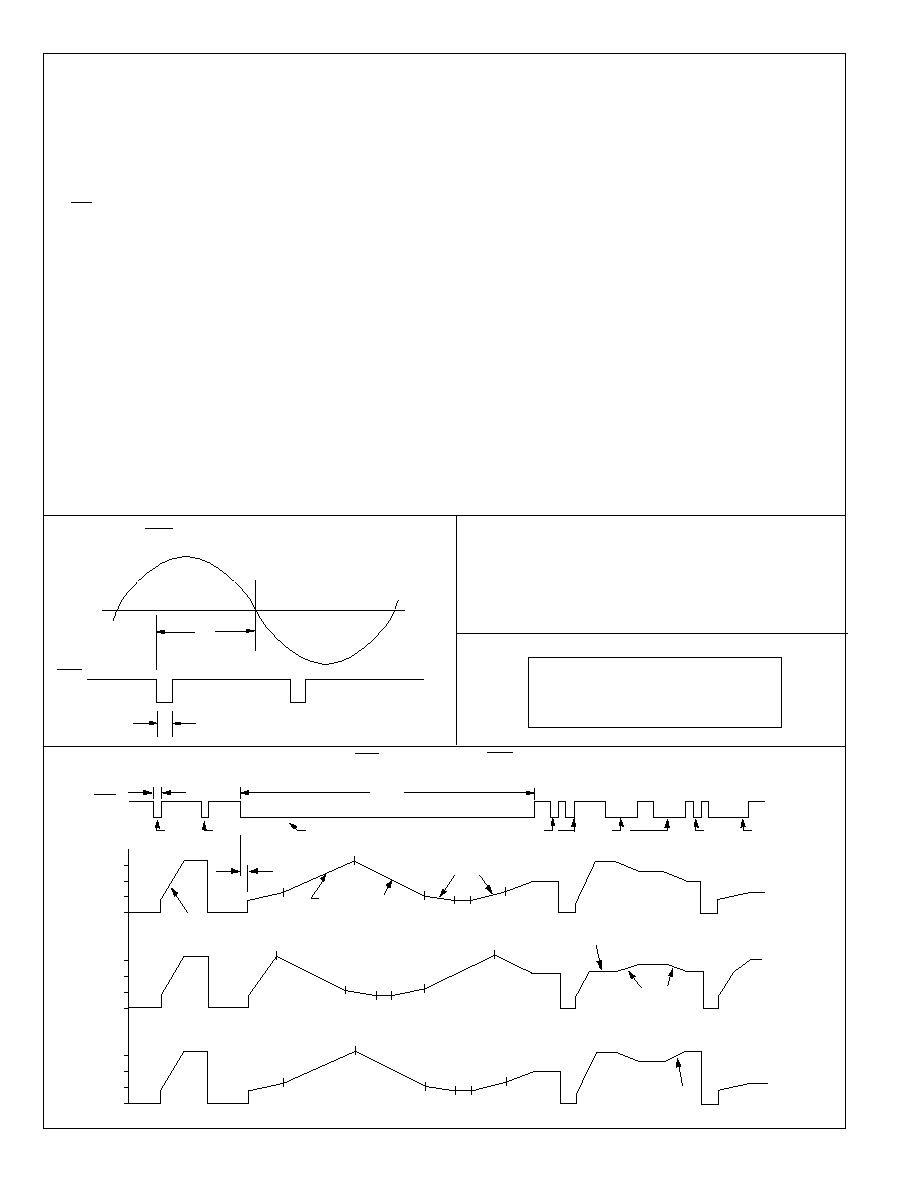
150∫
100∫
50∫
OFF
150∫
100∫
50∫
OFF
150∫
100∫
50∫
OFF
ÿ
MODE ÿ
ÿ
MODE 1
ÿ
MODE 2
SENS
T
S1
T
S2
342ms
SHORT
SHORT
LONG
SHORT
LONG
SHORT
LONG
A2
B2
B1
A1
A0
A2
B2
B1
A2
B2
B1
A1
A0
A0
A0
A1
A2
A2
SLOPE = S
BA
MEMORY
REVERSE
REVERSE
SLOPE = Ss
SLOPES = S
AA
FIGURE 3. LS7631 TRIG, ÿ vs TOUCH (SENS OR EXT)
¯
TRIG
S Y N C
T
W
FIGURE 2. TRIG OUTPUT CONDUCTION ANGLE, ÿ
The information included herein is believed to be
accurate and reliable. However, LSI Computer Systems,
Inc. assumes no responsibilities for inaccuracies, nor for
any infringements of patent rights of others which may
result from its use.
REPLACEMENT FOR P/N SLB 0587
LS7631 and LS7632 can be used in place of the SLB 0587
without modifying the application circuit recommended by
the manufacturer of that IC.
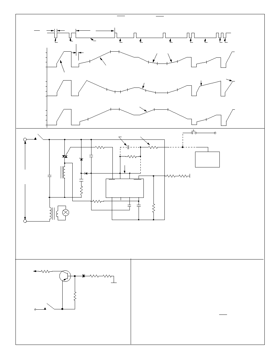
150∫
100∫
50∫
OFF
150∫
100∫
50∫
OFF
150∫
100∫
50∫
OFF
ÿ
MODE ÿ
ÿ
MODE 1
ÿ
MODE 2
T
S1
T
S2
342ms
SHORT
SHORT
SLOPE = S
S
SLOPE = S
AA
SLOPE = S
BA
LONG
LONG
LONG
LONG
A2
A0
A0
A1
B1
B2
A2
A2
B2
B1
A1
A2
B2
B1
A1
A0
A0
A0
A0
A2
A2
MEMORY
A2
MEMORY
SHORT
SHORT
REVERSE
REVERSE
SENS
LONG
FIGURE 4. LS7632 TRIG, ÿ vs TOUCH (SENS OR EXT)
7631/32-112102-4
EXT
10k
IN914
TOUCH PLATE
*R
200k
MPS8599
FIGURE 7. ELECTRONIC EXTENSION
*R
P
*R = 2M
for 115VAC
*R = 3.6M
for 220VAC
All Resistors 1/4W
EXTENSIONS: All switching and dimming functions can be
implemented by utilizing the EXT input. Use a pushbutton or
the electronic switch in conjunction with a Touch Plate as
shown in Figure 7. When the plate is touched, a logic high
level is generated at the EXT input of the IC for both half-
cycles of the line frequency. (See Figure 6)
APPLICATION EXAMPLE:
A typical implementation of the light dimmer circuit is shown in Fig. 6.
Here the brightness of the lamp is set by touching the touch plate.
The function of different components are as follows:
∑ The 5V DC supply for the chip is provided by Z, D1, R1, C2 and C5.
∑ R2 and C4 generate the filtered signal for the SYNC input
for synchronizing the internal PLL with the line frequency.
∑ R3 and C6 act as a filter circuit for the electronic extension.
If extensions are not used, the EXT input (Pin 6) should be
tied to Vss (Pin 7).
∑ R4, R5 and R6 set up the sensitivity of the SENS input.
∑ C3 is the filter capacitor for the internal PLL.
∑ R8 provides current limiting and isolation between the chip
output and the triac gate.
∑ C1 and L are RFI filter circuits.
P
1 1 5 V A C
OR
2 2 0 V A C
N
LAMP
C1
T
L
C2
R1
R2
R8
R3
C5
D1
1
2
3
4
8
7
6
5
R4
C3
C4
TRIG V
SS
EXT S E N S
V
DD
MODE
CAP SYNC
+
L S 7 6 3 1 / L S 7 6 3 2
R6
R5
FIGURE 6. A Typical Halogen Lamp Dimmer Wall Switch
G
MT2
MT1
Z
-
ELECTRONIC
EXTENSION
(FIG. 7)
EXTN
P
C6
S E E N O T E 3
S E E N O T E 2
R7
TOUCH
P L A T E
SEE
N O T E 4
C1 = 0.15µF, 200V
C1 = 0.15µF, 400V
C2 = 0.15µF, 200V
C2 = 0.082µF, 400V
C3 = 0.02µF, 10V
C4 = 0.002µF, 10V
C5 = 100µF, 10V
C6 = 0.1µF, 10V
R1 = 270
, 1/2W
R1 = 1k
, 1W
R2 = 680
, 1/4W
R2 = 1.5M
, 1/4W
R3 = 1.5M
, 1/4W
R4 = 1M
to 5M
, 1/4W
(Select for Sensitivity)
R5, R6 = 2.7M
, 1/4W
R5, R6 = 4.7M
, 1/4W
R7 = 150k
, 1/4W
R8 = 62
, 1/4W
D1 = 1N4148
Z = 5.6V, 1W (Zener)
T = Q4004L4 Typical Triac (1)
T = Q5003L4 Typical Triac (1)
L = 100µH (RFI Filter)
L = 200µH (RFI Filter)
(1) For loads greater than 6A,
use an alternistor
.
= component change for 220VAC
*
*
*
*
*
*
*
*
NOTES
1. All circuits connected by broken lines are optional.
2. C6 is used only with electronic extension
and R7 is used only with a pushbutton.
3. Connection between Pin 6 & Pin 7 should
be broken when EXT is used.
4. As a precaution, transformer should have
thermal protection.