80C300
4-1
1
MD400145/G
98012
80C300
Full Duplex CMOS Ethernet
10/100 Mega Bit/Sec Data Link Controller
Features
s
Low Power CMOS Technology
s
10/100 MBit Ethernet Controller Optimized for
Switching Hub, Multiport Bridge/Router, &
Server Applications
s
Meets ANSI/IEEE 802.3 and ISO 8802-3 Standards
for Ethernet (10Base-5) Thin Net (10Base-2)
(10Base-T) and the Proposed 100Base-T4,
100Base-TX Standards
s
10 MHz Serial/Parallel Conversion in 10 MBit/sec
Serial Mode.
s
Standard 10MBit/sec Serial Mode or
Programmable MII Ethernet Interface for 10/100
MBit/sec Applications
s
Programmability of Double Word Threshold
Count for Space Available/Data Available Ready
Condition for Transmit/Receive FIFOs
s
Auto Retransmit Upon Collision Sense
s
Preamble Generation and Removal
s
Automatic 32-Bit FCS (CRC) Generation and
Checking
s
Collision Handling, Transmission Deferral and
Retransmission with Automatic Jam and
Backoff Functions
s
Error Interrupt and Status Generation
s
Selectable Little Endian/Big Endian Transmit Byte
Ordering for FIFO Interface for Intel/Motorola
Compatibility
s
Single 5 V
�
5% Power Supply
s
Standard CPU and Peripheral Interface
Control Signals
s
128/128 Byte Independent Transmit/Receive FIFOs
with 32 Bit Data Path Interface
- 1 G Bits/sec (133 M Bytes/sec) Peak Data Rate
in 32 Bit Mode.
s
Loopback Capability for Diagnostics
s
32 Bit FIFO Data Path
Hurricane is a trademark of SEEQ Technology Inc.
s
Inputs and Outputs TTL Compatible
s
The Following Additional Features can be
Programmed for the 80C300
- 64 bit Multicast Filter
- Reports Status of "SQE" During Transmits
- Transmit No CRC Mode
- Transmit No Preamble Mode
- Transmit Packet Autopadding Mode
- Receive CRC Mode
- Disable Self-Receive on Transmit Mode
- Disable Further Transmissions when Both
Transmit Status Registers are Full
- Disable Loading the Transmit Status for
Successfully Transmitted Packets
- Disable the Receive Interrupts Independent
of the Receive Command Register Setting
- Successful Packet Transmit Completion
Feature
s
Full Duplex Operation
- Provides 20/200 Mbps Bandwidthfor
Switched Networks
- Supports AutoDUPLEX Mode for Automatic
Full Duplex Operation
s
Transmit Status on a Per Packet Basis Reports the
Following
- Occurrence of a Transmit FIFO Underflow
- Transmit Collision Occurrence
- 16 Collision Occurrence
- Carrier Sense Error During Transmission
- 10/100 Mbit/sec Transmit Clock Detect
- Late Collision Occurrence
- Transmission Successful
- Transmission Deferred
Full Duplex
HURRICANE
TM
Note: Check for latest Data Sheet revision
before starting any designs.
SEEQ Data Sheets are now on the Web, at
www.lsilogic.com.
This document is an LSI Logic document. Any
reference to SEEQ Technology should be
considered LSI Logic.

80C300
4-3
3
MD400145/G
Illustrations
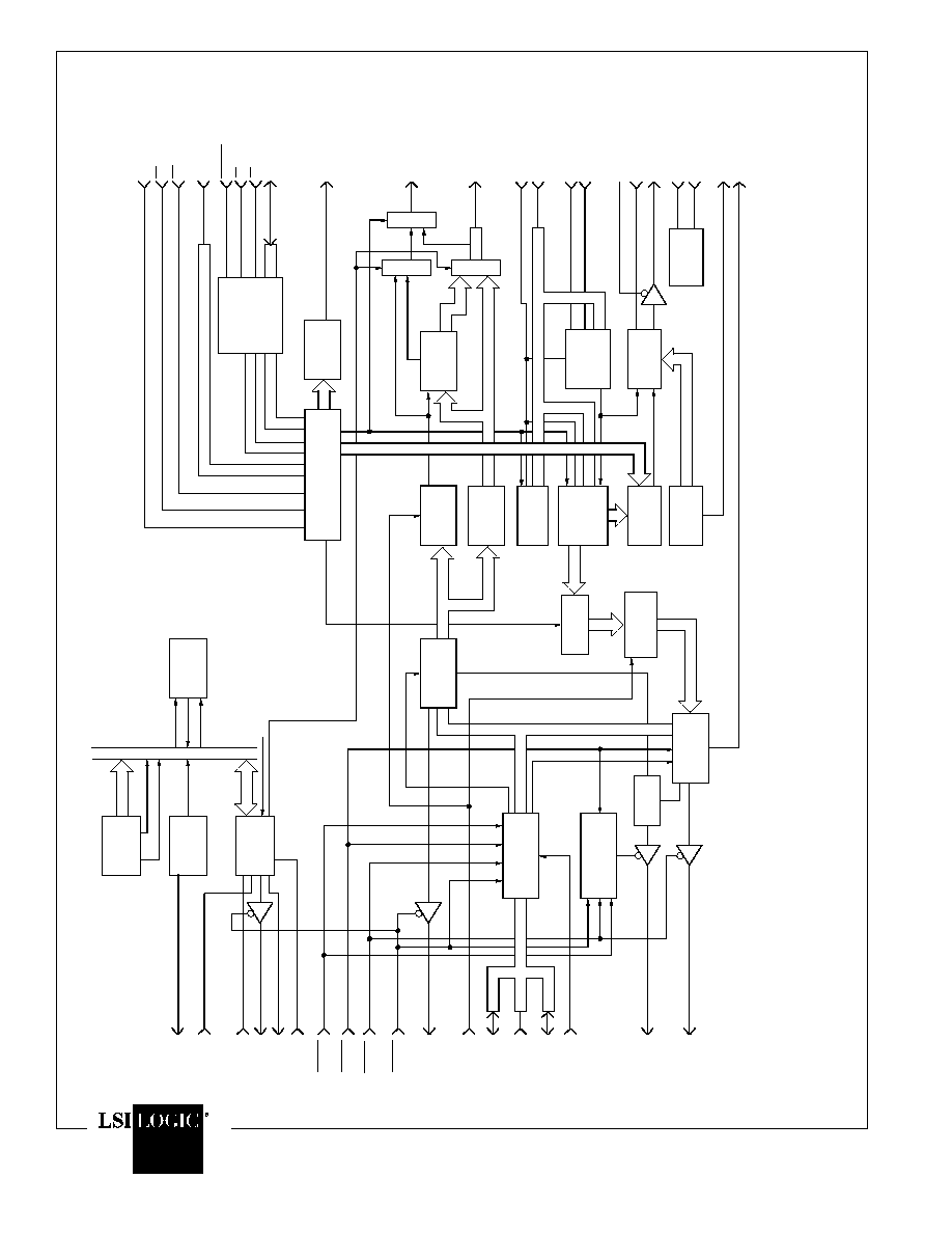
Figure 1. Functional Block Diagram of the 80C300
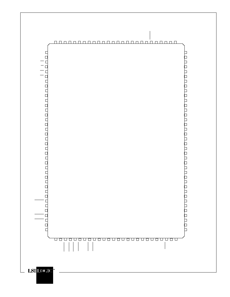
Figure 2. 80C300 Pin Configuration
Figure 3. Typical Application Example
Table of Contents
1.0 Pin Description
2.0 Introduction
3.0 Functional Description
3.1 Frame Format
3.2 Packet Transmission
3.2.1 Controlling Transmit Packet
Encapsulation
3.2.2 Transmission Initiation/Deferral
3.2.3 Collision on Transmit
3.2.4 Transmit Termination Conditions
3.2.5 Error Conditions That Will Cause
TXRET to go HIGH
3.2.6 Detection and Clearing of a Transmit
Retry Condition
3.3 Packet Reception
3.3.1 Preamble Processing
3.3.2 Address Matching
3.3.3 Conditions of Receive Termination
3.3.4 Using Rxabort to Terminate Reception
3.3.5 Receive Discard Conditions
3.4 System Interface
3.5 FIFO Interface
3.5.1 Little and Big Endian Format
3.5.2 Transmit FIFO Interface
3.5.3 Receive FIFO Interface
3.5.4 Special Conditions on RXRD_TXWR
Clock Input
3.6 Register Interface
3.6.1 Internal Channel Register
Addressing Table
3.6.2 Station Address Register
3.6.3 Transmit Command Register
3.6.4 Receive Command Register
3.6.5 Transmit Status Register
3.6.6 Receive Status Register
3.6.7 Configuration Registers
3.6.8 FIFO Threshold Register
3.6.8.1 FIFO Threshold Register
Address Settings Table
3.6.9 Defer Register Calculations for 80C300
3.7 Management Interface of the MII
3.8 Counters
4.0 DC Characteristics
5.0 AC Characteristics
5.01 Command/Status Interface Read Timing
5.02 Command/Status Interface Write Timing
6.0 Ethernet Transmit and Receive
Interface Timing
6.01 Ethernet Transmit Interface Timing
6.02 Ethernet Receive Interface Timing
7.0 Transmit Data Interface Timing
7.01 Transmit Data Interface Write Timing 1
7.02 Transmit Data Interface Write Timing 2
8.0 Receive Data Interface Timing
8.01 Receive Data Interface Read Timing 1
8.02 Receive Data Interface Read Timing 2
9.0 Transmit Data Interface Timing on
Exception Conditions
10.0 Receive Data Interface Timing on
Exception Conditions
11.0 Reset Timing


