 | –≠–ª–µ–∫—Ç—Ä–æ–Ω–Ω—ã–π –∫–æ–º–ø–æ–Ω–µ–Ω—Ç: LSI22902 | –°–∫–∞—á–∞—Ç—å:  PDF PDF  ZIP ZIP |

November 2000
1
Copyright © 2000 by LSI Logic Corporation. All rights reserved.
Æ
LSI22902/22903 Host Adapter
to Intel ISP1100 Internet Server
Quick Installation Guide
The LSI Logic LSI22902/22903 PCI to Dual Channel Ultra2 SCSI Low
Profile Host Adapter is ideally suited for installation into the Intel ISP1100
Internet Server Platform. In this application, the host adapter provides
one internal LVD only channel and one LVD or SE external channel.
1 Overview
This document describes installing the LSI22902/22903 into the Intel
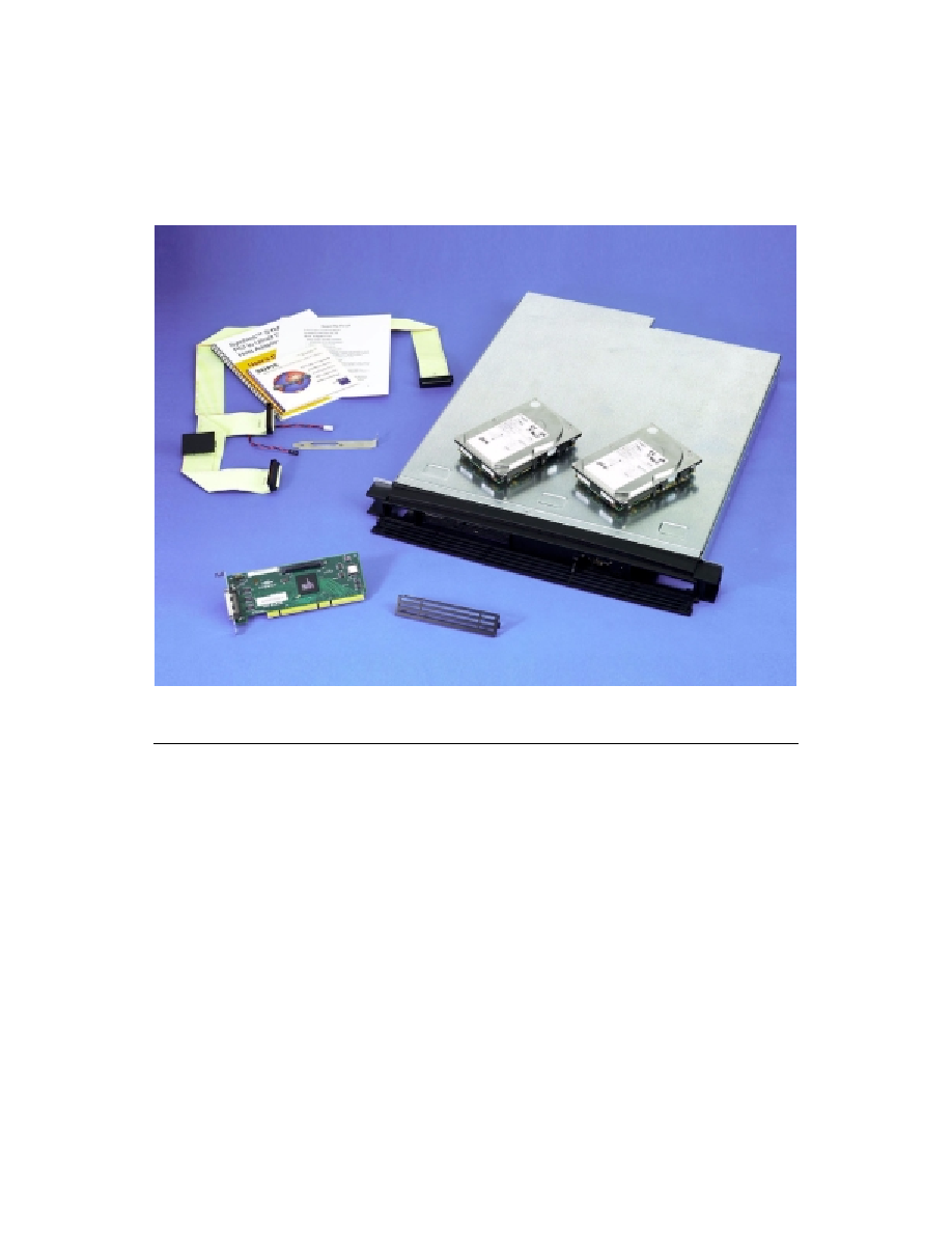
ISP1100 Internet Server Platform. The host adapter kit includes the
following items. Refer to
Figure 1
for a picture of the complete kit.
∑
LSI22902 or LSI22903 Host Adapter.
∑
Host Adapter user's guide.
This manual contains detailed engineering documentation for the
LSI22902/22903.
∑
PCI Storage Device Management SDMS 4.0 CD.
This CD contains software and associated documentation for the
LSI22902.
∑
Internal SCSI cable with attached Ultra2 LVD terminator.
∑
High Density (HD) LED connector.
∑
An additional card guide for a standard PC chassis.
2
LSI22902/22903 Host Adapter to Intel ISP1100 Internet Server
Figure 1
LSI22902 Host Adapter Kit
2 Installation
The installation process contains the following four major sections:
∑
Section 2.1, "Setting up the Installation"
∑
Section 2.2, "Installing the Host Adapter Board"
∑
Section 2.3, "Installing New Drives"
∑
Section 2.4, "Completing the Installation"
LSI22902/22903 Host Adapter to Intel ISP1100 Internet Server
3
2.1 Setting up the Installation
Important:
Make sure the ISP1100 server is turned off and is not
plugged into an electrical outlet. Take all precautions to
minimize ESD. A ground strap is recommended.
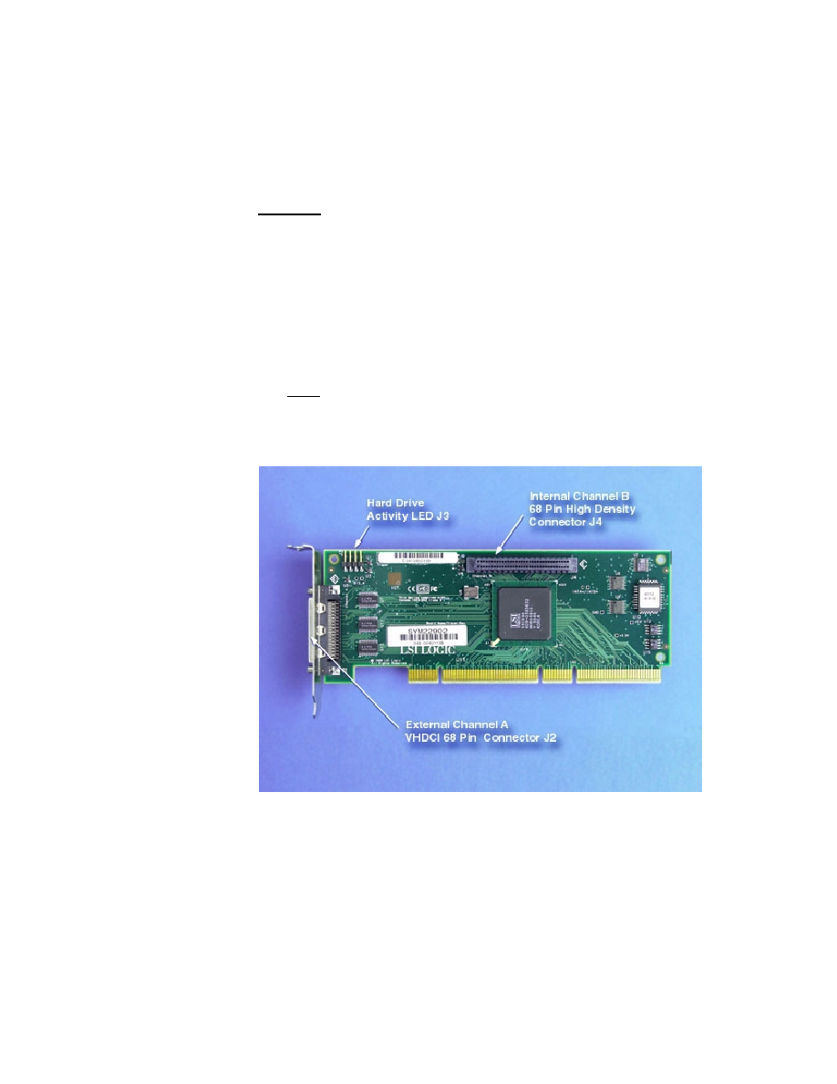
Step 1.
Identify the parts listed below on the LSI22902/22903. Refer to
Figure 2
for a photograph of the board.
∑
Internal Channel B, 68-pin HD connector, J4.
∑
Hard drive activity LED connector, J3.
∑
External Channel A, VHDCI 68-pin connector, J2.
Note:
Detailed specifications for both boards are contained in the
host adapter user's guide.
Figure 2
LSI22902/22903 Close-up
Step 2.
Remove the top cover of the Intel ISP1100 server by removing
the top plate screw.
Step 3.
Carefully slide the top cover plate back until the beveled front
edge clears the chassis.

4
LSI22902/22903 Host Adapter to Intel ISP1100 Internet Server
Step 4.
Lift the cover using the notch in the front of the cover and
remove.
Refer to
Figure 3
for a photograph of the ISP1100.
Figure 3
Intel ISP1100 Internet Server
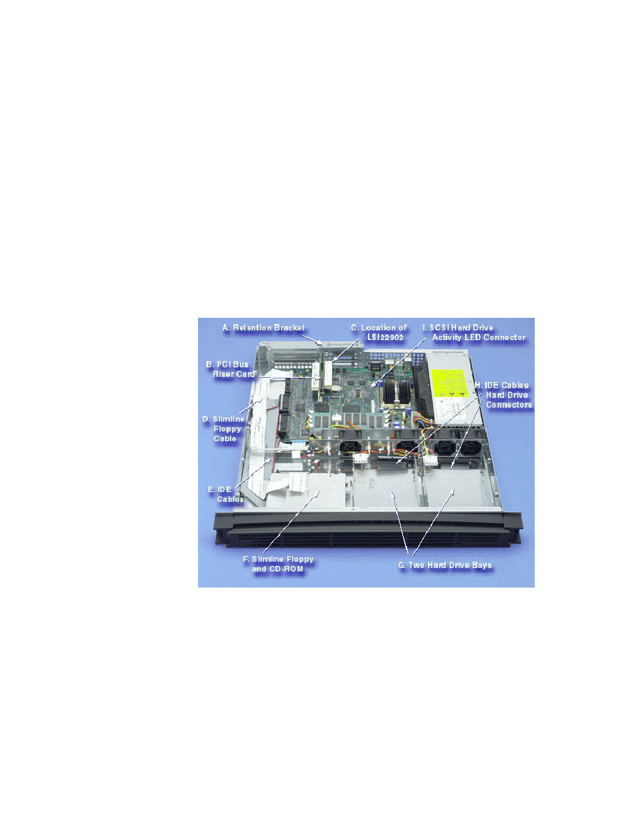
Step 5.
Locate the components of the ISP1100. Refer to
Figure 4
for a
photograph of an opened unit.
a. Retention bracket.
b. PCI bus riser card.
c. Area for mounting the LSI22902/22903.
The slot on the right side of the riser card.
d. Slimline floppy cable.
White cable approximately 1 inch wide.
e. IDE cables for hard drives and CD-ROM.
Gray cables approximately 2 inches wide.
LSI22902/22903 Host Adapter to Intel ISP1100 Internet Server
5
f. Slimline floppy and CD-ROM assembly.
g. Two hard drive bays.
The ISP1100 is provided with a floppy cable for hard drives,
but no drives are installed or included.
h. IDE cable with hard drive connectors.
The cables are routed under the drive bays and the
CD-ROM/floppy assembly.
i. SCSI hard drive activity LED connector .
J11 on the mainboard.
Figure 4
Intel ISP1100 Server, Cover Removed
2.2 Installing the Host Adapter Board
This section of the manual describes setting up the Intel ISP1100 server
and installing the LSI22902/22903 and other system hardware.
Step 1.
Identify the PCI low profile slot for the host adapter board.